Free cookie consent management tool by TermsFeed Cookies

Home / Product / Automotive Industry /

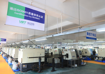
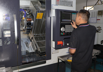
16 years of experience in CNC machining auto parts, different processing and manufacturing techniques, reducing processing costs. There are 2000+ automotive CNC machining parts samples, you can view the factory online, contact us immediately to get discounts and samples.


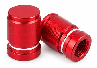
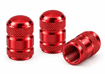
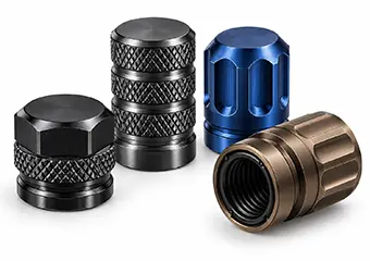
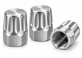
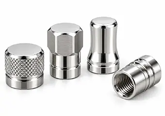
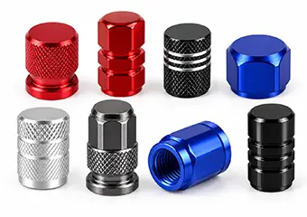
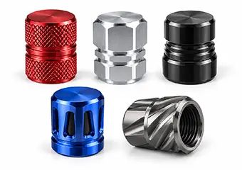
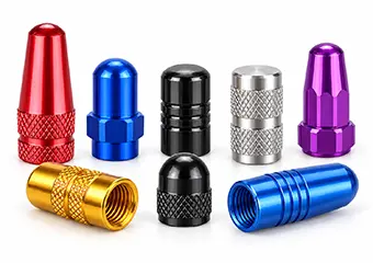
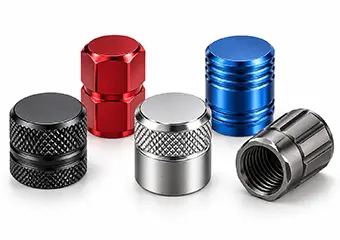
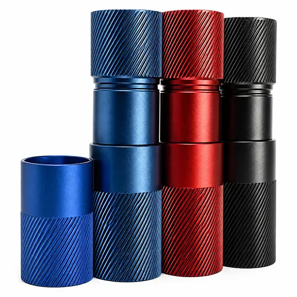
Custom CNC Machined Tire Valve Stem Caps & Covers

Custom CNC Machined Tire Valve Stem Caps & Covers

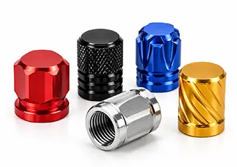
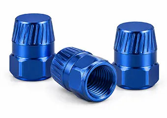
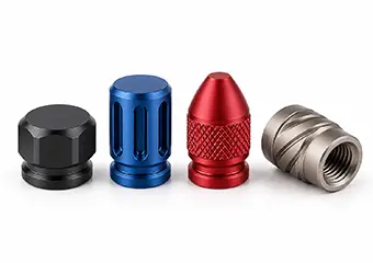
Custom CNC tire valve stem caps and covers from your drawings. VMT helps control internal thread fit, mating valve compatibility, anodized or plated dimensions, custom logos and repeat production consistency.

Product Specification:

  • Services : Custom CNC Machined Tire Valve Stem Caps & Covers
  • Supply Ability : 100000 Pieces per Month
  • Material:Aluminum(AL 6061-T6, 6063, 7075-T 2014 2017 2011 etc), Stainless Steel(303,304,316L, 17-4(SUS630) etc ), Titanium (TA1,TA2/GR2, TA4/GR5, TC4, TC18 etc), Brass, POM, PEEK, Other Materials. :
  • Surface Roughness : Ra 0.1~3.2
  • Surface Treatment : Customer's Demand, Type II Anodizing, Hard Anodizing, Bead Blasting + Anodizing, Polishing, Brushing, PVD Coating, Nickel / Chrome Plating, Laser Marking, etc.
  • Tolerance : ±0.005 mm.(Custom Available)
  • Drawing format : CAD file (dwg, dxf, pdf, etc.), 3D File (step, stp, etc), drawing design.
  • Standard or not : Non standard,customized as drawing or sample
Inquiry Now
Product description
Drawing-Based Custom CNC Manufacturing

Custom CNC Machined Tire Valve Stem Caps & Covers

VMT manufactures custom CNC tire valve stem caps and covers based on your 2D drawings, 3D models, mating valve specifications, materials, finishes and branding requirements. From internal threads and sealing interfaces to knurling, anodizing and cosmetic details, we help control the features that affect fit, appearance and repeatability from prototype validation through production.

For a faster engineering review, send the mating stem thread, required cap depth, sealing structure, finish / color and target quantity together with your drawing.

DFM Review Before Production CNC Turning + Milling Support Critical Feature Inspection Prototype → Repeat Production
Custom CNC Machined Tire Valve Stem Caps & Covers
Fit · Seal · Finish · Repeatability

Critical Problems We Help You Control in Custom Tire Valve Stem Caps

A valve stem cap may be small, but thread fit, internal depth, sealing interfaces, material pairing and post-finish dimensions can directly affect assembly and long-term use. VMT reviews these features together with your drawing and mating valve requirements so potential problems can be identified before repeat production.

01

Internal Thread Fit

Internal threads that are too tight, too loose or inconsistent after finishing can cause assembly problems. VMT reviews the specified thread, machining allowance and finishing sequence, then verifies critical thread features according to the drawing requirements before shipment.

Control: Thread machining + post-finish verification
02

Internal Depth & Valve Clearance

A cap may thread correctly but still bottom out too early or interfere with the internal valve structure. We review thread depth, internal cavity depth and required clearance against the mating component information provided by your engineering team.

Control: Depth + clearance review against mating data
03

Seal, Washer & O-Ring Interfaces

Some custom caps use sealing washers, O-rings or polymer inserts rather than a simple metal-to-metal interface. Seat geometry, groove dimensions and internal shoulder positions are reviewed together so sealing or assembly features remain consistent with the intended design.

Control: Seat / groove / shoulder relationship
04

Cap & Valve Stem Material Compatibility

Aluminum, brass, stainless steel and titanium do not behave the same when paired with different valve stem materials or surface finishes. Material selection should therefore consider the mating component, operating environment and finishing requirements rather than appearance alone.

Control: Cap + stem + finish review
05

Dimensions After Anodizing or Plating

Anodizing, plating and other surface treatments can affect threads, bores and mating surfaces. VMT reviews areas that may require allowance, masking or post-finish verification so finished parts remain aligned with drawing-defined fit requirements.

Control: Finish allowance + masking + reinspection
06

Cosmetic & Batch Consistency

Color variation, scratches, inconsistent polishing and incorrect logo position can cause rejection even when dimensions are acceptable. Machining, surface finishing coordination, final appearance inspection and protective packaging are planned together for cosmetic custom parts.

Control: Finishing coordination + appearance inspection
Custom Structures

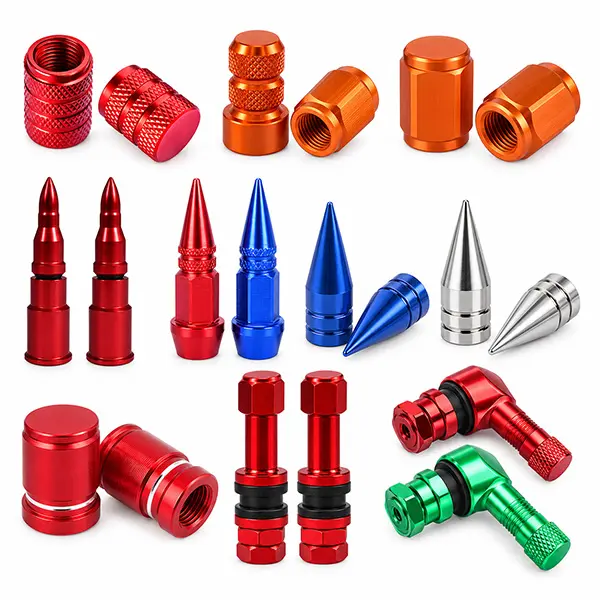
Custom CNC Tire Valve Stem Caps & Covers We Machine

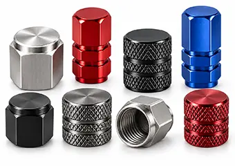
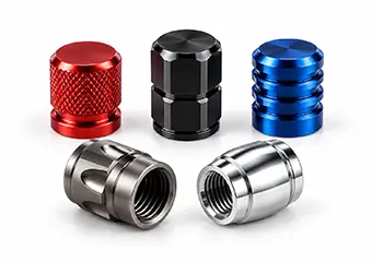
VMT supports drawing-based valve cap designs rather than a fixed catalog of standard parts. Different exterior profiles, thread structures, sealing features, finishes and branding details can be evaluated according to your mating valve, application and production requirements.

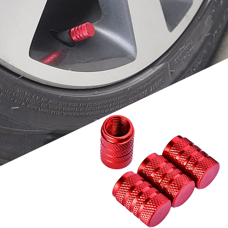
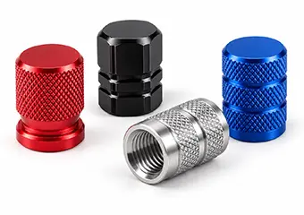
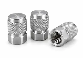
Custom CNC Machined Knurled Air Tire Rim Wheel Valve Stem Caps & Covers

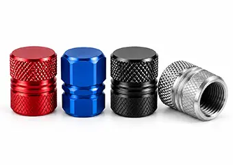
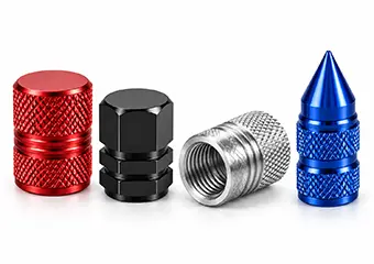
Knurled Valve Stem Caps

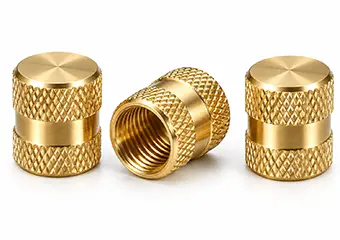
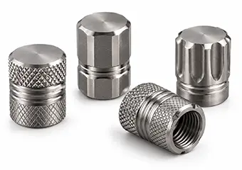
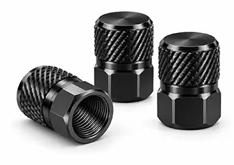
CNC turned valve caps with straight, diamond or drawing-defined knurl patterns for improved grip. Thread fit, overall diameter, knurl consistency and cosmetic surfaces are controlled according to your drawing and finish requirements.

Custom CNC Machined Hex & Wrench-Flat Valve Stem Caps

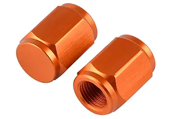
Hex & Wrench-Flat Valve Caps

Custom valve caps with external hexagons, flats or tool-engagement features. CNC turning and secondary milling can be combined to control thread position, flat geometry, edge condition and the relationship between functional and visible surfaces.

Custom CNC Machined Low-Profile Valve Stem Caps

Low-Profile Valve Stem Caps

Compact cap designs for restricted wheel, rim or surrounding component space. Overall height, internal cavity depth and wall structure are reviewed to maintain required clearance without compromising drawing-defined thread and mating features.

Custom CNC Machined Extended Valve Stem Caps

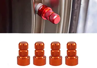
Extended Valve Stem Caps

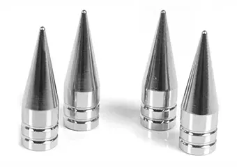
Longer caps can include stepped bodies, deep internal cavities or extended decorative profiles. Machining sequence and tool access are reviewed to control wall thickness, internal depth, thread position and exterior concentricity.

Custom CNC Machined Logo & Branded Stem Caps & Covers

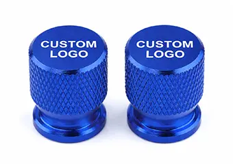
Custom Logo & Branded Valve Caps

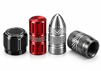
CNC machined caps can incorporate laser marking, engraving, machined branding areas or other customer-defined identification. Logo position, surface preparation and finishing sequence are coordinated to support a consistent branded appearance.

Custom CNC Machined Profile Valve Stem Caps & Covers

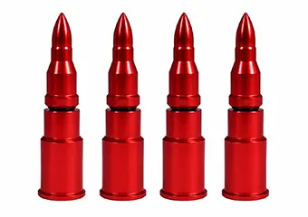
Custom-Profile Valve Stem Caps

Bullet, stepped, tapered, multi-diameter and other non-standard profiles can be manufactured from customer drawings. Turning and milling strategies are selected according to geometry, appearance surfaces and secondary machining requirements.

Custom CNC Machined Sealing Valve Stem Caps & Covers Bodies

Sealing Valve Cap Bodies

Caps designed around O-rings, sealing washers or internal inserts require more than thread machining alone. Internal shoulders, seal seats, grooves and mating surfaces are produced according to the specified functional relationships in the drawing.

Custom CNC Machined Tire Valve Stem Caps & Covers From Your Drawing or Sample

Valve Caps From Your Drawing or Sample

For projects that do not match a standard cap structure, VMT can review your 2D drawing, 3D model or reference sample and develop a machining approach based on material, tolerances, surface finish and production quantity.

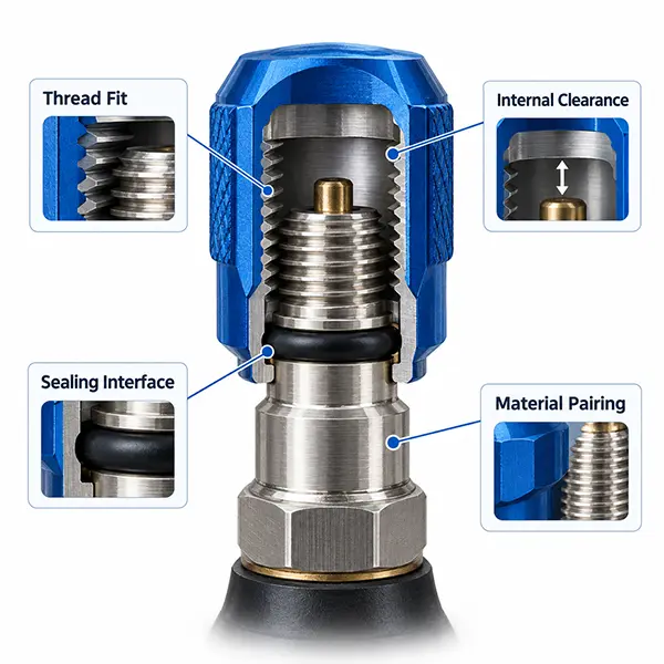
Analysis of Cross-Sectional Structure and Sealing of Custom CNC-Machined Tire Valve Caps
Assembly-Level Engineering

Thread, Seal & Mating Valve Stem Compatibility

A custom valve cap should be reviewed as part of an assembly, not as an isolated CNC part. Thread specification, engagement depth, internal clearance, sealing method, cap material and mating valve stem material can all influence the final fit.

Before machining, VMT can review the information supplied for the mating valve stem together with your cap drawing. For critical projects, attention is placed on female thread geometry, thread depth, internal shoulder position, valve-core clearance, O-ring or washer interfaces, finish-sensitive areas and other drawing-defined functional surfaces.

This approach helps reduce the risk of producing parts that meet isolated dimensions but do not perform correctly in the final assembly.

Thread Fit

Thread type, engagement and machining sequence are reviewed against the drawing and mating component requirements.

Internal Clearance

Internal depth and shoulder locations are checked to reduce interference or premature bottoming risks.

Sealing Interface

O-ring, washer or insert features are machined according to the specified seat, groove and contact geometry.

Material Pairing

Cap material, mating valve stem material and finish requirements can be reviewed together when compatibility matters.

Looking for the valve stem itself rather than the cap? See VMT's custom CNC tire valve stems and tubeless valve components.

Risk Reduction Before Cutting

DFM Review Before CNC Machining Your Tire Valve Stem Caps

The main DFM risk in a small valve cap is not its size; it is the interaction between the internal thread, usable engagement, cavity depth, thin walls, secondary features and the final coating. VMT reviews those relationships before material is committed so the quote and machining route are based on the finished assembly condition.

For drawing-critical features, VMT can evaluate precision requirements down to ±0.005 mm after engineering review. Designated critical dimensions or thread features can be included in a 100% inspection plan when the project requires it.

1-on-1Engineering DFM review
100+ CNC MachinesPrototype and repeat-production capacity
±0.005 mm*Critical-dimension capability after engineering review
100%*Inspection for designated critical features when required
View Valve Cap DFM Review Table
DFM Check Risk If It Is Missed VMT Control Method Verification / Customer Result
Thread Specification & Mating Stem Correct-looking parts can still bind, wobble or fail to assemble if pitch, thread form or mating information is unclear. Review the drawing callout, thread standard / class and available mating-stem information before programming; select a suitable turning / threading method and inspection approach. Designated critical threads can be checked 100% with a suitable thread gauge or drawing-defined method, reducing wrong-thread and fit rejection risk.
Thread Depth & Effective Engagement Too little engagement can feel loose; excessive internal depth may add cycle time without improving function. Compare thread length, usable engagement and tool access with the mating geometry, rather than programming thread depth as an isolated number. Depth verification is tied to the drawing requirement so the cap reaches the intended assembly position without relying on hand fitting.
Internal Cavity & Valve-Core Clearance A cap can pass thread inspection yet bottom out on an internal shoulder or interfere with the valve-core area. Review cavity depth, shoulder position and the customer-supplied mating-valve geometry together during DFM. Critical cavity / shoulder dimensions are measured before release, helping prevent bottoming and internal interference during assembly.
Wall Thickness & Small-Part Stability Thin walls can move during roughing, threading or secondary machining and create OD / ID or cosmetic variation. Separate roughing and finishing where needed, reduce unsupported cutting, and plan workholding around the final wall structure. Critical dimensions can be controlled to the drawing requirement; precision down to ±0.005 mm is evaluated only after geometry, material and process review.
Knurl, Hex Flats, Slots & Logo Features Secondary operations can shift feature position or leave inconsistent edge / appearance relationships. Define a common datum strategy and sequence turning, knurling, milling and engraving around the functional axis of the cap. First-article verification confirms feature location before repeat production, reducing secondary-operation rework.
Anodizing / Plating on Functional Areas Coating build-up can tighten threads, change sealing surfaces or create an acceptable machined part that fails after finishing. Identify finish-sensitive threads and mating areas before machining; review allowance, masking or protected areas with the finishing plan. Designated post-finish critical dimensions can be rechecked 100%, so acceptance is based on the condition the customer actually assembles.
Cosmetic Surfaces & Branding Scratches, color variation, poor logo placement or visible tool witness can cause rejection even when dimensions pass. Define A-surfaces, finish direction, logo location and handling / packaging requirements before production. Critical appearance areas can be included in 100% visual inspection to the agreed sample or cosmetic standard.
DFM output should change a production decision. The review is used to confirm the machining route, datum strategy, finish-sensitive areas and inspection checkpoints before the project moves into prototype or repeat production.
Material Selection

Materials for Custom CNC Tire Valve Stem Caps

Material selection for a custom valve stem cap should consider more than appearance. Machinability, strength, weight, surface finishing, mating valve material and operating environment can all affect the final design. VMT can review material options against your drawing, finish requirements and mating component before production.

Custom 6061-T6 Aluminum Tire Valve Stem Caps & Covers CNC Machining

6061-T6 Aluminum

A widely used option for lightweight custom valve caps requiring CNC turning, milling, knurling and anodizing. It offers a practical balance of machinability, strength and cosmetic finishing for OEM and aftermarket projects.

Aluminum CNC machining

Custom 6063 Aluminum Tire Valve Stem Caps & Covers CNC Machining

6063 Aluminum

Suitable for projects where surface appearance and anodized finish are important design considerations. Final material selection should still be reviewed together with thread geometry, wall thickness and the mating valve structure.

Custom 7075-T6 Aluminum Tire Valve Stem Caps & Covers CNC Machining

7075-T6 Aluminum

Higher-strength aluminum for compact, thin-wall or premium designs where additional mechanical strength may be useful. Machining strategy and finishing requirements should be reviewed carefully for small detailed components.

7075 aluminum CNC machining

Custom 303 304 316 Stainless Steel Tire Valve Stem Caps & Covers CNC Machining Manufacturing

303 / 304 Stainless Steel

Stainless steel provides a heavier, durable metallic feel and corrosion resistance for premium or functional valve caps. Tooling, surface finish and edge condition are controlled according to the required appearance and part geometry.

Stainless steel CNC machining

Custom C360 Brass Tire Valve Stem Caps & Covers CNC Machining

C360 Brass

Brass offers excellent machinability and a distinctive premium appearance. For valve cap applications, the mating valve stem material and environmental exposure should be considered during engineering review rather than selecting brass based on appearance alone.

Brass CNC machining

Custom Titanium Grade 5 Tire Valve Stem Caps & Covers CNC Machining

Titanium Grade 5

Titanium supports lightweight, high-strength premium designs where material value and appearance justify the additional machining cost. It is typically selected for specialized or high-end custom valve cap projects.

Titanium CNC machining

Material pairing matters at the mating interface. When different metals, coatings or environmental conditions are involved, review the cap material together with the mating stem material, surface finish and sealing structure before finalizing production.
Process Strategy

CNC Machining Strategies for Small Precision Valve Caps

Valve caps combine features that are easy to underestimate: a functional internal thread, short tool engagement, deep internal shoulders, knurling, thin walls, secondary flats and cosmetic surfaces. VMT plans turning, milling, finishing and inspection as one route so the finished cap remains consistent with the drawing and mating-valve requirements.

CNC turning and threading custom valve stem caps
CNC turn-mill machining for custom valve stem cap features
CNC Turning of Cap Bodies — Keep OD, ID, Shoulder and Thread Relationships Stable
OD, ID, shoulders and threads are concentrated in a short component, so unnecessary re-clamping can add datum error. Where geometry permits, VMT sequences the turned features around one functional axis and completes critical relationships before secondary operations. This reduces datum-transfer error and supports more stable concentric and axial relationships from prototype through repeat production.
Internal Thread Machining — Reduce Tight, Loose or Inconsistent Assembly
Limited tool space, burrs and surface-finish build-up can all affect a small internal thread. VMT selects the threading method according to thread size, depth, material and finish, while controlling the entry chamfer and burr condition. Finish-sensitive threads are identified before anodizing or plating, and designated critical threads can be verified with suitable GO / NO-GO or drawing-defined gauges, including 100% inspection when required by the project.
Deep Internal Cavities & Shoulders — Avoid Tool-Access and Bottoming Problems
Deep cavities can create problems with tool reach, chip evacuation, shoulder access and depth accuracy. During DFM, VMT reviews the tool length-to-diameter relationship, boring access and chip path before machining starts. Roughing and finishing can be separated when cavity stability requires it, helping keep the internal depth and shoulder position within the drawing-defined requirement and reducing late tool-access changes.
Knurling — Control Grip, Finished Diameter and Batch Appearance
Knurl pattern, crest condition, finished diameter and visible consistency can drift if they are treated as cosmetic details only. VMT confirms the knurl type, target OD and appearance reference during first-article production, then controls the knurling sequence before final cosmetic finishing. This gives engineering and quality teams an approved grip and appearance reference for repeat batches.
Hex Flats & Secondary Milling — Keep Features Aligned to the Turned Axis
Secondary flats, slots or logo features can shift relative to the turned body when the part is re-clamped. VMT uses controlled locating surfaces and a common datum strategy for secondary milling while minimizing unnecessary setup transfers. This improves repeatability between the internal thread, turned OD and milled exterior geometry and reduces secondary-operation rework.
Thin-Wall Structures — Reduce Distortion During Machining and Finishing
Material removal can quickly reduce the stiffness of a small cap body. Workholding pressure, roughing and finishing sequence, tool engagement and final passes are adjusted to the actual alloy and remaining wall thickness. Critical dimensions can be evaluated for precision capability down to ±0.005 mm after engineering review rather than applying the same tolerance claim to every geometry.
Logo & Decorative Features — Coordinate Machining, Engraving and Final Finish
Logo position, engraving depth and process order can create visible mismatch or rework after finishing. VMT coordinates the machining or engraving location with the defined A-surfaces, anodizing / plating sequence and final inspection plan before release. Critical appearance areas can be checked against the approved sample or cosmetic standard to reduce branding inconsistency.
Process choice follows the part. A simple turned cap should not be forced into an unnecessarily expensive process, while a complex profile should not be forced into an unstable setup only to reduce cycle count. The objective is the lowest-risk route that still meets the drawing, finish and production-volume requirements.
Process Capability Applied to the Features That Matter: VMT has 100+ CNC machines and supports CNC turning, milling and combined secondary operations. For critical dimensions, capability down to ±0.005 mm can be evaluated after engineering review; designated critical features can be placed on a 100% inspection plan when required by the drawing or quality plan.
Appearance + Finished Fit

Surface Finishes, Colors & Branding for Custom Valve Stem Caps

For custom valve caps, surface finish is often both a functional and cosmetic requirement. The finishing process can influence color, texture, corrosion performance, logo appearance and critical dimensions. VMT coordinates machining and finishing requirements so functional interfaces and visible surfaces are considered together.

Custom CNC Machined Type II Anodizing Tire Valve Stem Caps & Covers

Type II Anodizing

Suitable for aluminum valve caps requiring color, corrosion protection and a clean branded appearance. Internal threads and other mating features can be reviewed for finish allowance, masking or post-finish verification.

Custom CNC Machined Bead Blasting and Anodizing Tire Valve Stem Caps & Covers

Bead Blasting + Anodizing

Bead blasting creates a uniform matte texture before anodizing and is commonly used for premium aftermarket components. Surface preparation, cosmetic areas and handling requirements are coordinated to reduce visible inconsistency.

Custom CNC Machined Polishing and Anodizing Tire Valve Stem Caps & Covers

Polishing + Anodizing

Polishing before anodizing can create a brighter, more decorative appearance. Because polished surfaces can make scratches and handling marks more visible, cosmetic inspection and protective packaging become especially important.

Custom CNC Machined Hard Anodizing Tire Valve Stem Caps & Covers

Hard Anodizing

Hard anodizing can be considered when the design requires a more wear-resistant surface. Critical internal threads and mating areas should be reviewed before finishing because coating build-up may affect final fit.

Custom CNC Machined Brushing Tire Valve Stem Caps & Covers

Brushing

Mechanical finishing can create brushed, satin or polished metal appearances for premium valve cap designs. Direction, consistency and surface protection should be defined clearly when appearance is part of the acceptance standard.

Custom CNC Machined Nickel Chrome Plating Tire Valve Stem Caps & Covers

Nickel / Chrome Plating

Nickel or chrome finishes can provide a bright metallic appearance and additional surface protection. Plating thickness, thread fit and cosmetic inspection should be considered together during process planning.

Custom CNC Machined PVD DLC & Special Coatings Tire Valve Stem Caps & Covers

PVD / DLC & Special Coatings

PVD and DLC-style coatings can support premium dark or metallic finishes where brand differentiation is important. Coating suitability depends on base material, geometry, required appearance and functional surfaces.

Custom CNC Machined Laser Marking & Engraving Tire Valve Stem Caps & Covers

Laser Marking & Engraving

Add a personal touch to your tire valve stem caps with custom engravings. Whether it's your initials, a logo, or a design of your choice, engravings make your caps uniquely yours.

Cosmetic quality is part of the manufacturing plan. A dimensionally correct part can still be rejected for scratches, color variation, inconsistent polishing or poor logo placement. Cosmetic requirements should therefore be defined before production, not only checked at final inspection. See VMT's surface finishing services.
Finished-Part Verification

Critical Dimensions & Inspection for Custom Valve Stem Caps

A valve cap should be accepted in the condition the customer will actually assemble. VMT therefore combines in-process inspection with finished-part verification, focusing on the thread, internal depth, sealing features, exterior geometry and cosmetic surfaces defined as critical on the drawing or quality plan.

Quality inspection for CNC machined valve stem caps

Inspection Built Around Assembly and Finished Condition

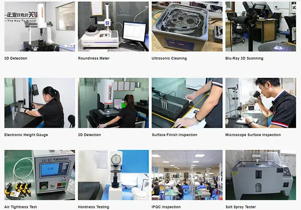
VMT's broader quality system includes 12 inspection processes. For valve-cap projects, the inspection plan can combine thread gauges, dimensional measurement, CMM or optical methods where appropriate, plus pre-finish and post-finish checks for features affected by anodizing or plating.

12-Step QCIncoming → in-process → final → outgoing control
3 Verification GatesPre-finish → post-finish → final release where applicable
100%*Designated critical dimensions / appearance points when required
CMM + GaugesMethod selected according to feature geometry
View Critical Dimensions & Inspection Table
Critical Feature Failure Risk Inspection / Control Method Acceptance / Customer Result
Internal Thread Tight, loose or incorrect thread prevents reliable mating-stem assembly. Suitable thread gauge or drawing-defined method; verify after finishing when coating can affect the functional thread. Designated critical threads can be checked 100%, reducing assembly rejection before shipment.
Thread Depth & Engagement Insufficient engagement or premature bottoming changes the final installed position. Depth verification against the drawing and mating-stem requirement. Confirms the cap reaches the intended assembly depth instead of relying on manual fitting at the customer's line.
Internal Cavity / Valve-Core Clearance Internal interference can occur even when the thread itself passes inspection. Dimensional depth / shoulder verification; use mating information where supplied. Reduces the risk of the cap contacting the valve-core area or bottoming before full engagement.
Seal / O-Ring / Washer Seat Incorrect groove, shoulder or seat geometry changes seal compression or insert location. Dimensional / profile inspection according to the drawing; first-article fit review where mating elements are available. Supports repeatable seal placement and assembly rather than checking only the cap's outside dimensions.
OD / Overall Height / Hex Flats Variation affects grip, wheel / rim clearance, tool engagement and exterior appearance. Dimensional inspection with the method selected for feature size and tolerance; CMM / optical support where geometry requires it. Critical dimensions can be evaluated for capability down to ±0.005 mm after engineering review.
Knurl Pattern & Finished OD Uneven knurl depth or crest condition changes hand feel and visible batch consistency. First-article reference + dimensional / visual checks during production. Creates an approved reference for repeat lots and reduces batch-to-batch grip / appearance variation.
Logo / Marking Position Incorrect orientation or placement creates immediate brand-quality rejection. Visual / positional inspection against the approved artwork and location reference. Critical branding features can be included in 100% appearance inspection when required.
Post-Finish Thread & Mating Fit Anodizing or plating can change effective dimensions after machining has already passed inspection. Identify coating-sensitive areas before finishing and recheck designated features after the final surface process. Acceptance is based on the finished part the customer receives, not only the pre-finish machined blank.
Cosmetic Surface Scratches, dents, color shift or uneven texture can reject a functionally correct branded part. Visual inspection to the agreed A-surface / approved sample, followed by protective packaging appropriate to the finish. Critical appearance points can be inspected 100% so approved cosmetic condition is maintained through shipment.
Inspect the finished part, not only the machined part. For anodized, plated or coated valve caps, designated critical features can be reverified after finishing. VMT's 12-step quality-control system combines incoming, in-process, final and outgoing inspection rather than relying on one end-of-line check. See CNC machining quality assurance.
Validate Before Scale-Up

From Prototype Validation to Repeat Production

A successful valve cap project should move smoothly from design review and prototype validation into repeat production. VMT supports this transition by reviewing the machining process, critical dimensions, finish requirements and inspection points before production volume increases.

1

Drawing & DFM Review

Review drawing, CAD, mating valve, material, finish, logo and quantity requirements before production planning.

2

Prototype Machining

Validate tool access, thread structure, cavity depth, knurling, secondary features and drawing-defined details.

3

Fit & Cosmetic Validation

Evaluate thread fit, mating interface, appearance, finish, color and branding details before process release.

4

Process Confirmation

Standardize machining sequence, critical inspection points, finish requirements and packaging expectations.

5

Repeat Production

Use the confirmed process with in-process and final inspection applied to the critical features defined for the project.

Why prototype validation matters: skipping validation can turn a minor thread-engagement, internal-clearance, knurl or anodized-fit issue into a repeated batch problem. Prototype review allows these issues to be identified while changes are still easier to manage.
Applications

Applications for Custom CNC Tire Valve Stem Caps

Custom valve stem caps are used across OEM, aftermarket, powersports and branded accessory projects where fit, appearance and repeat production matter more than using a standard off-the-shelf cap. VMT machines valve caps according to the specific thread, material, finish, branding and assembly requirements of each application.

Custom CNC Machined Tire Valve Stem Caps & Covers for Automotive OEM & Mobility Systems

Automotive OEM & Mobility Systems

Custom valve caps for vehicle, wheel and mobility programs where thread fit, appearance, corrosion considerations and repeat production must align with OEM drawings and assembly requirements.

Custom CNC Machined Tire Valve Stem Caps & Covers for Motorcycle & Powersports

Motorcycle & Powersports

Compact and custom-profile valve caps for motorcycles, ATVs, scooters and other powersports applications requiring reliable fit, durable finishes and brand-specific appearance.

Custom CNC Machined Tire Valve Stem Caps & Covers for Performance & Motorsport

Performance & Motorsport

Lightweight aluminum, titanium or stainless valve caps for performance applications where custom geometry, premium finishes and consistent machining support differentiated component design.

Custom CNC Machined Tire Valve Stem Caps & Covers for Forged & Custom Wheels

Forged & Custom Wheels

Branded or color-matched valve caps for forged wheels and custom rim programs, with attention to thread compatibility, wheel styling, anodized color and cosmetic surface requirements.

Custom CNC Machined Tire Valve Stem Caps & Covers for Bicycle & E-Bike Component

Bicycle & E-Bike Components

Small custom valve cap components for bicycle and e-bike applications where compact geometry, lightweight materials, color finishes and brand details are part of the product design.

Custom CNC Machined Tire Valve Stem Caps & Covers for Private Label & Branded Accessories

Private Label & Branded Accessories

Custom CNC valve caps developed for aftermarket brands and accessory companies requiring unique profiles, logos, colors, surface finishes and repeatable production rather than standard catalog parts.

Multi-Color Anodized AL6063-T6 Aluminum Electronic Product Shell Case CNC Machining
VMT Published Manufacturing Case

Case Study: Controlling Color Difference on 100,000 Anodized Aluminum Parts

A customer required 100,000 AL6063-T6 electronic product shells in four anodized colors with a 30-day delivery target. The manufacturing risk was not simply machining the aluminum; it was keeping the appearance inside an acceptable range while four colors were processed across a large production quantity.

AL6063-T6Material
100,000 pcsProduction quantity
4 ColorsAnodized appearance requirement
30 DaysDelivery target

Customer problem: anodized color can shift from day to day. With four color groups and a 100,000-piece order, waiting until final inspection to discover drift would create a large batch-consistency and schedule risk.

VMT control method: VMT assigned dedicated personnel to follow the anodizing process, retained production samples from each day as color references, and used upper / lower comparison limits to control visible color variation. The documented process route was CNC turning → CNC machining → anodizing / oxidation → CNC conductive processing → cleaning and degreasing → full inspection.

Why this matters for custom valve caps: branded aluminum valve caps can have the same combination of machined geometry, anodized color, visible A-surfaces and repeat-production requirements. The case demonstrates why machining, finishing references, production follow-up and inspection need to be controlled as one manufacturing system when cosmetic consistency matters.

Customer Trust

What Customers Value When Working With VMT

Clear engineering communication, reliable sample validation, controlled finished appearance and protective packaging are the details that turn a CNC quote into a repeatable production relationship. The feedback below shows the practical results customers value after working with VMT.

VMT customer review engineering communication

Engineering Communication

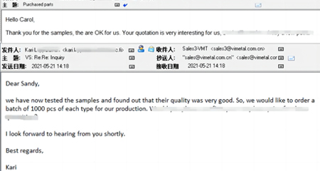
“Your quote is very good. I am working with my customer; if he approves my quote I will have other work that I will need you to quote on.”

Clear quotation support and responsive communication help customers keep projects moving internally.

VMT customer review sample approval and production order

Samples Approved → Production

“We have now tested the samples and found out that their quality was very good. So, we would like to order a batch of 1000 pcs of each type for our production.”

Prototype validation should create a clear path into real production, not remain a one-off sample.

VMT customer review finished product and branding

Finished Product & Branding

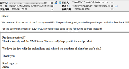
“Products received! Thanks Wendy and the VMT team. We are really happy with the end product. We love the few with the etched logo…”

Surface appearance and marking contribute to whether a cosmetic CNC project feels successful.

VMT customer review protective packaging

Packaging & Delivery Confidence

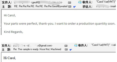
“The new parts arrived today and they are perfect… I was amazed at the packing. Every part was securely packed and easy to access.”

Protective packaging helps anodized, polished and coated parts arrive in the condition that passed final inspection.

Prepare Your RFQ

What Should You Send Us for a Custom Valve Stem Cap Quote?

The more complete your project information is, the more accurately VMT can review the machining process, material, surface finish and inspection requirements. You do not need every detail finalized before contacting us — we can review available drawings and discuss missing information during DFM.

Information What to Send Why It Helps
2D Drawing PDF / DWG / marked drawing Defines dimensions, tolerances, threads, notes and inspection requirements
3D CAD Model STEP / STP / IGES Supports geometry, tool-access and custom-profile review
Mating Valve Stem Drawing / dimensions / sample information Supports thread engagement, clearance and assembly review
Thread Specification Drawing callout / standard Critical for machining and inspection planning
Material Grade or performance requirement Determines machining, cost and finishing compatibility
Surface Finish / Color Process / color / texture reference Affects process sequence, fit and cosmetic planning
Logo / Branding Vector artwork / position reference Supports marking and cosmetic review
Seal / Washer / O-Ring Part specification / interface details Supports seat, groove and internal shoulder review
Quantity Prototype + expected production Supports fixture and production planning
Cosmetic Standard A-surfaces / approved sample Clarifies scratches, gloss, texture and color acceptance
Packaging Requirements Protection / labeling needs Protects anodized, polished or plated surfaces
FAQ

Frequently Asked Questions About Custom CNC Tire Valve Stem Caps

These questions focus on the fit, finishing, material-pairing and inspection risks that usually need an engineering decision before a custom valve cap moves into production.

Q: Can you machine both the internal thread and custom exterior features in one valve-cap project?
A: Yes. VMT can combine CNC turning with secondary milling, knurling, drilling and engraving according to the geometry. During DFM we decide which relationships should remain on the same functional datum and which features require a second setup. This is especially important for hex flats, side holes or logos because unnecessary re-clamping can shift their relationship to the turned body. First-article verification is used before repeat production, and designated critical dimensions can be inspected 100% when required.
Q: How do you control internal thread fit after anodizing or plating?
A: We identify coating-sensitive threads and mating surfaces before machining, then review whether the project needs machining allowance, masking / protection or finished-condition reinspection. The correct choice depends on thread size, coating system and mating requirements, so we do not assume one rule fits every cap. Where the thread is defined as critical, VMT can use a suitable GO / NO-GO or drawing-defined inspection method and perform 100% post-finish verification according to the agreed quality plan.
Q: Should the internal thread be anodized, masked or machined after finishing?
A: That decision should be made from the final assembly requirement, not from appearance alone. Leaving the thread anodized may change effective fit; masking can preserve dimensions but creates a finish boundary; post-machining can restore a functional surface but adds an operation. VMT reviews thread tolerance, required corrosion protection, mating-stem material and finish thickness during DFM, then recommends a process route that can be inspected in the final condition rather than relying on a generic finishing rule.
Q: Can you review our cap together with the mating valve stem or TPMS valve structure?
A: Yes, and this is preferred when fit risk is important. Send the mating-stem drawing, sample dimensions or available interface information together with the cap drawing. VMT reviews thread engagement, cap depth, valve-core clearance, shoulder position, sealing features and material pairing as one assembly. This helps catch a common problem: every individual cap dimension may be inside tolerance, but the assembled cap still bottoms out early, feels loose or interferes with the actual valve structure.
Q: How do you prevent a valve cap from bottoming out or contacting the valve-core area?
A: Thread fit alone does not prove internal clearance. During DFM we compare effective thread engagement, cavity depth, internal shoulders and the customer-supplied mating geometry. The inspection plan then includes the dimensions that control the final installed position, such as thread depth and internal cavity / shoulder depth. When mating samples or interface data are available, fit verification can be added to dimensional inspection so the risk is identified before a production batch reaches customer assembly.
Q: Can you machine O-ring, sealing-washer or polymer-insert features into the cap?
A: Yes. Internal seal seats, shoulders, grooves and insert-locating features can be included in the CNC machining plan when they are defined on the drawing. For these projects, send the seal / washer / insert specification whenever possible. We review groove width, depth, shoulder position, tool access and the relationship to the thread and internal cavity, then select a dimensional or profile inspection method that verifies the feature controlling actual seal placement.
Q: How do you reduce galvanic-corrosion or seizing risk between a metal cap and valve stem?
A: Material pairing should be reviewed together with the environment and finish. If dissimilar metals will contact each other, VMT can review whether the customer design uses an anodized / plated barrier, sealing washer, O-ring or polymer insert and whether direct metal-to-metal contact is intended. We do not claim one material combination is universally safe; the engineering decision depends on the mating-stem material, exposure to moisture / salts and the product's service conditions. Include this information in the RFQ so the interface can be evaluated before material is released.
Q: How do you control knurling, hex flats and other visible features across repeat batches?
A: VMT first defines the functional datum, target OD / flat geometry and visible-surface requirement, then verifies the first article before repeat production. Knurl type, crest condition, finished diameter, secondary-milling position and edge condition are checked according to the drawing or approved sample. For appearance-critical features, inspection can combine dimensional checks with an agreed visual reference. This reduces the risk that a later batch technically fits but looks or feels different from the approved sample.
Q: How are critical valve-cap dimensions inspected before shipment?
A: VMT uses a 12-step quality-control workflow that includes incoming, in-process, final and outgoing inspection. The method is selected by feature: thread gauges for critical threads, dimensional gauges / CMM / optical methods for geometry as appropriate, and visual standards for cosmetic surfaces. For anodized or plated parts, designated features can be checked before and after finishing. Where the project requires it, critical dimensions and critical appearance points can be set for 100% inspection rather than relying only on final sampling.
Q: What should we define as the cosmetic acceptance standard for anodized valve caps?
A: Define which faces are A-surfaces, acceptable color range or reference sample, gloss / texture direction, scratch / dent limits, logo position and any surfaces that may show fixture or handling marks. For color-sensitive production, an approved sample or retained comparison standard is more useful than a vague instruction such as “no color difference.” VMT can coordinate machining, surface preparation, finishing follow-up, final appearance inspection and protective packaging around that agreed standard so purchasing and quality teams have a clear acceptance basis.
Bottom Engineering Guide

Engineering Guide to Custom CNC Tire Valve Stem Caps

Use this guide when reviewing a new valve-cap design or preparing an RFQ. It focuses on the decisions that most directly affect thread fit, internal clearance, material compatibility, finished appearance, inspection and repeat-production cost.

1. Design the Internal Thread Around the Finished Condition, Not Only the Machined Blank

The internal thread is usually the first functional feature to review because a valve cap can look perfect and still fail immediately if the finished thread is too tight, too loose or positioned at the wrong depth. Start by defining the mating stem thread, thread standard / class, usable engagement and the installed position you expect. Then check whether the cap can bottom out on an internal shoulder or contact the valve-core area before full thread engagement is reached.

Surface finishing has to be included in the same decision. Anodizing and plating can change the effective condition of small threads and mating surfaces. Depending on the finish, thread size and corrosion requirement, the practical route may involve machining allowance, masking / protection or post-finish verification. VMT reviews these areas during DFM rather than waiting until the first finished sample is difficult to assemble.

For drawing-critical projects, thread fit should be verified using a suitable thread gauge or drawing-defined method, and designated critical thread features can be included in a 100% inspection plan. The goal is simple: the cap should be accepted in the finished condition the customer actually assembles, not only when it leaves the CNC machine.

Discuss Your Project With Engineering

2. Review Cap Material Together With the Mating Valve Stem

Material selection is not only a question of weight or premium appearance. The cap and stem create a material pair, and that pair may be exposed to water, road salt, cleaning chemicals and temperature changes. Aluminum, brass, stainless steel and titanium also respond differently to anodizing, plating and direct metal-to-metal contact.

For new designs, send the mating-stem material and any existing coating / insert information with the RFQ. If the design uses an O-ring, sealing washer or polymer barrier, include that component as well. VMT can then review machining, finishing and the interface as one system. This avoids choosing a material that machines easily but creates an avoidable fit, corrosion or service-environment risk after assembly.

3. Define Thread Engagement, Internal Depth and Valve-Core Clearance Together

Three dimensions often control whether a cap actually installs correctly: usable thread engagement, internal cavity depth and the position of internal shoulders. If these are designed separately, a cap can pass thread inspection and still bottom out too early or contact the valve-core area.

During DFM, VMT compares the cap drawing with mating-valve data supplied by the customer. The drawing should identify the dimensions that set the final installed position, not only the overall cap height. For critical projects, depth verification and mating-part checks can be added to the inspection plan. This gives engineering and quality teams a measurable acceptance condition instead of solving interference by hand during assembly.

4. Choose Knurling, Hex Flats and Exterior Profiles From Use + Manufacturing Requirements

Knurling is useful when the cap is intended to be tightened by hand and can also create a strong visual texture. Hex flats provide a more geometric appearance and can support tool engagement, but usually introduce a secondary milling operation after turning. Bullet, tapered and stepped profiles may require additional toolpaths or setup changes depending on the geometry.

The engineering decision should therefore include grip, overall diameter, visible style, secondary-operation cost and how the feature will be inspected. VMT confirms the functional axis first, then plans knurling or milling around that datum. An approved first article can establish the pattern, edge condition and exterior appearance that later batches are expected to match.

5. Treat O-Rings, Washers and Inserts as Functional Geometry

If the cap includes a sealing washer, O-ring or polymer insert, the seat, groove and internal shoulder are not secondary details. They determine where the sealing element sits, how much it is compressed and whether the cap can reach the intended thread engagement without interference.

Provide the seal / insert specification whenever possible. VMT reviews groove width, depth, corner radii, internal shoulder location and tool access together with the surrounding thread and cavity. The inspection method is then selected for the actual geometry. This reduces the risk of receiving dimensionally acceptable caps that still require sorting or manual adjustment during customer assembly.

6. Define Cosmetic Acceptance Before Anodizing, Plating or Laser Marking

For branded wheel, motorcycle and aftermarket programs, appearance can be an acceptance requirement equal to thread fit. Define which faces are A-surfaces, what color / texture reference should be used, where logos must sit and what scratch or handling marks are unacceptable. Without this information, both customer and supplier can inspect the same part and reach different conclusions.

VMT coordinates machining, deburring, surface preparation, finishing, marking and protective packaging around those visible areas. In VMT's published 100,000-piece / four-color anodizing case, retained daily samples and upper / lower visual references were used to control production color variation. The same principle is useful for valve-cap programs: establish an approved visual standard before repeat production, then inspect to that standard rather than relying on vague wording.

7. Build the Inspection Plan Around Failure Modes, Not the Number of Dimensions

A long inspection report is not automatically a strong quality plan. Start with the dimensions that can actually cause failure: internal thread, thread depth, valve-core clearance, seal seat, overall height, secondary flats and post-finish fit. Then add appearance points such as knurl condition, logo position and anodized A-surfaces when the product is cosmetic.

VMT's broader system uses 12 inspection processes covering incoming, in-process, final and outgoing control. Depending on the project, the valve-cap plan can use thread gauges, dimensional measurement, CMM / optical methods, pre-finish checks and post-finish verification. Designated critical dimensions or critical appearance points can be inspected 100% when required, so quality resources are concentrated on the features that control assembly and acceptance.

8. Control Cost by Simplifying the Right Features — Not the Functional Ones

Valve-cap cost is influenced by more than material price. Internal thread complexity, deep cavities, thin walls, secondary milling, knurling, custom logo work, surface finishing, inspection level and packaging all add operations. A cap that needs multiple re-clamps and cosmetic rework can cost more than a slightly heavier design that turns cleanly in fewer stable operations.

A useful RFQ should include the 2D drawing, 3D model, mating-stem information, material, finish / color, seal or insert details, logo file, prototype quantity and expected production volume. VMT uses that information to review whether features can share datums, whether secondary operations are necessary and which dimensions actually need tight control. DFM should reduce avoidable machining and inspection cost without weakening the interfaces that determine fit, sealing or brand appearance.

Ready to Review Your Custom Valve Stem Cap Project?

Send us your drawing, CAD model, mating valve information, material, finish and quantity requirements. VMT can review manufacturability, machining strategy and critical interfaces before production.

Useful information: 2D / 3D Drawing · Mating Valve Stem · Thread · Material · Finish · Logo · Quantity · Inspection Requirements

Related suggestion

Write us

Give us a call or send an inquiry to our emailbox, we will answer your doubts according to your customers' requirements, and quote you immediately.

Upload 2D/3D drawings

Upload Your Files or Contact inquiry@vimetal.com.cn to Get Instant Quote (Please attach 2D CAD drawings and 3D CAD models in any format including STEP, IGES, DWG, PDF, STL, ZIP, etc.).
Upload files ( Max file size: 20MB )

Upload 2D/3D drawings

Upload Your Files or Contact inquiry@vimetal.com.cn to Get Instant Quote (Please attach 2D CAD drawings and 3D CAD models in any format including STEP, IGES, DWG, PDF, STL, ZIP, etc.).
Upload files ( Max file size: 20MB )
+86 15099911516
loading