Key Blade Fit & Retention
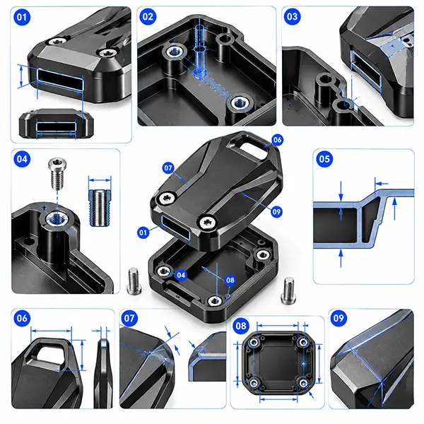
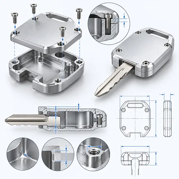
We reviews slot width, insertion depth, locating surfaces and retention geometry together so the key can assemble securely without excessive force or looseness.

Home / Product / Automotive Industry /
16 years of experience in CNC machining auto parts, different processing and manufacturing techniques, reducing processing costs. There are 2000+ automotive CNC machining parts samples, you can view the factory online, contact us immediately to get discounts and samples.
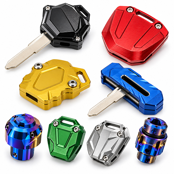
Product Specification:


VMT provides custom CNC machining for motorcycle, automotive, motorsport and premium mechanical key head covers based on your drawings, physical samples and assembly requirements. We support different materials, blade-fit interfaces, fastening features, cosmetic finishes and prototype-to-repeat-production requirements.
We manufacture custom CNC key head covers to your drawing, approved sample and assembly requirements.
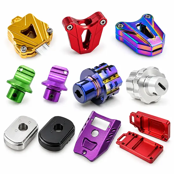
A key head cover is compact, but its function depends on how the blade interface, locating features, fastening points, mating surfaces and exterior geometry work together. VMT plans machining and inspection around these connected risks.
We reviews slot width, insertion depth, locating surfaces and retention geometry together so the key can assemble securely without excessive force or looseness.
Mating datums, locating steps, screw positions and exterior profiles are controlled as one feature set to reduce uneven joint gaps and assembled profile mismatch.
Hole position, thread depth, counterbores, edge distance and tool access are reviewed before machining to reduce assembly rework and fastening problems.
Fixture support, cutting sequence and finishing passes are adjusted around thin ribs, pockets and skeletonized geometry to reduce chatter, distortion and edge damage.
Chamfers, radii and visible transitions are controlled together with deburring and handling so the finished part feels refined and does not expose sharp edges.
Functional and cosmetic areas are identified before anodizing, plating, PVD, polishing or other finishing so critical fits can be protected or re-verified where required.
Different structures require different machining and assembly control. We machine the key head covers and supporting mechanical components that most directly affect fit, assembly, durability and appearance. The examples below illustrate common design directions; your project does not need to match a standard model.
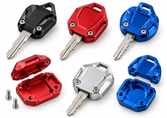
Upper and lower housings machined as an assembled system so screw fit, joint gap, profile matching and finished appearance can be controlled together.
Request a Quote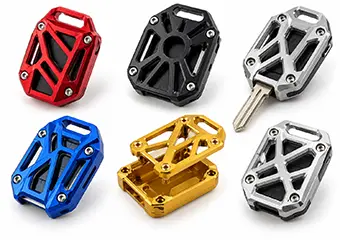
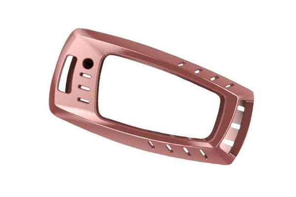
Weight-reduced key head structures with pockets, open areas and narrow ribs that still need enough local stiffness around blade seats and fastening zones.
Request a Quote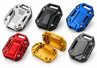
Faceted or wrap-around shell designs with features on multiple orientations, requiring stable datum transfer and multi-face machining to keep the exterior geometry consistent.
Request a Quote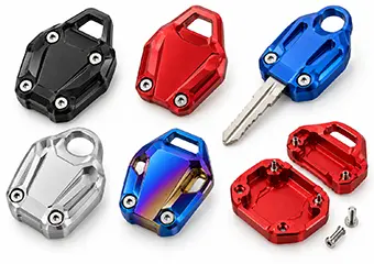
Key heads combining the main housing with ring lugs, slots or attachment points, reducing add-on parts while keeping the carry interface aligned with the body.
Request a Quote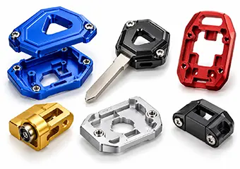
Key-ring holes, slots and integrated attachment structures are machined relative to the blade interface and surrounding wall thickness.
Request a Quote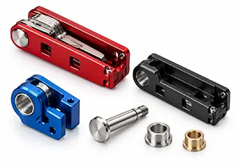
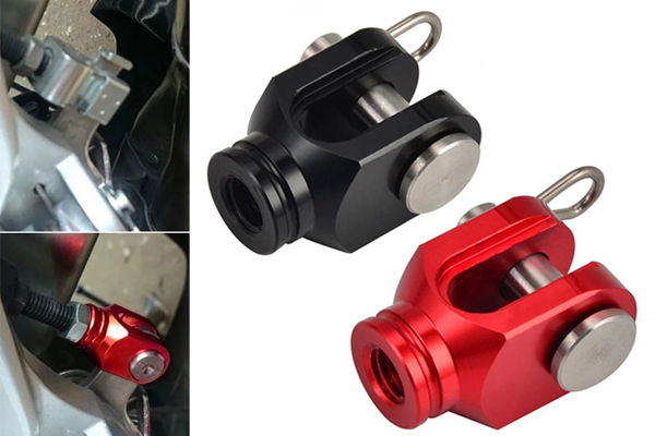
Pivot bodies, pins, spacers and bushings for flip-key mechanisms where hole position, wear behavior and rotational fit influence long-term opening and closing performance.
Request a Quote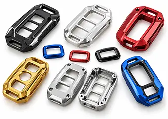
Smaller visible trim parts around button or logo areas where clean edge quality, cosmetic consistency and repeatable finishing often matter more than overall size.
Request a Quote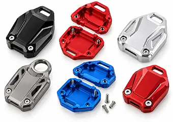
Send CAD data, drawings, photos or sample information for a manufacturing review based on your actual structure rather than a fixed product specification.
Request a QuoteThe most important dimensions are the ones that work together in the assembled key. We review functional datums, blade interfaces, fastening features, mating surfaces and visible geometry before machining, and we can recheck designated critical dimensions 100% according to your drawing requirements.
Before cutting material, we review blade fit, assembly structure, wall thickness, fastening features, machining access, material, finish and expected production quantity as one manufacturing system. Our goal is to identify risk before prototype approval is delayed by avoidable machining or finishing issues.
The manufacturing route is selected according to actual geometry, material, tolerance, appearance and quantity requirements rather than forcing every project into the same machine or setup.
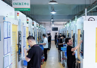
Used for most shell bodies with pockets, slots, profiles and screw features, supporting efficient multi-face machining for mainstream key head cover structures.
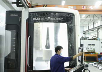
Useful for more angular, sculpted or difficult-to-clamp designs where reducing extra setups improves datum consistency and visible-surface protection.
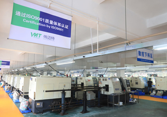
Applied to pivot pins, bushings, spacers and cylindrical support parts where stable diameters, concentricity and repeatable assembly fit are required.
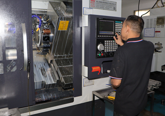
Combines turning and milling for compact mechanical parts that need flats, cross-holes, off-axis slots or multiple features completed with fewer setups.
Features on different orientations are planned around common datums. Precision CNC milling and, where justified, 5-axis CNC machining can reduce unnecessary datum transfers.
Workholding, cutting sequence and tool engagement are adjusted around narrow ribs, thin walls and skeletonized structures to reduce vibration and dimensional movement.
For parts with significant material removal, roughing, semi-finishing and final finishing can be separated so critical dimensions are completed after the structure becomes more stable.
Locating and clamping are planned around functional reference surfaces while avoiding unnecessary contact with important cosmetic faces where the design allows.
Blade slots, narrow pockets, small holes, threads and counterbores are reviewed for tool reach, depth and surrounding wall geometry.
Visible surfaces are considered during toolpath, deburring and handling planning, while approved fixtures and inspection points support later repeat production.
The right material depends on weight, strength, wall thickness, appearance, wear requirements and product positioning. VMT does not limit this product to aluminum.
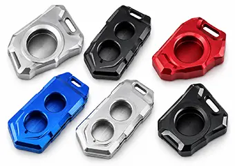
Lightweight, machinable and well suited to anodized motorcycle, automotive and branded accessory designs.
Aluminum CNC machining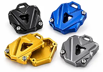
Useful for higher-strength, thinner or performance-oriented structures where low weight remains important.
Explore aluminum machining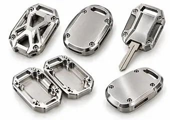
Suitable when rigidity, wear resistance and a heavier premium metallic feel matter more than minimum weight.
Stainless steel CNC machining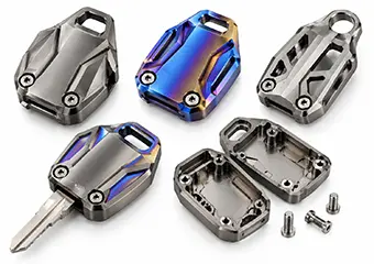
Supports premium lightweight designs requiring high strength-to-weight performance and distinctive material positioning.
Titanium CNC machining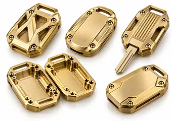
Offers distinctive natural color, dense tactile feel and decorative finishing flexibility for luxury or EDC-oriented designs.
Brass CNC machining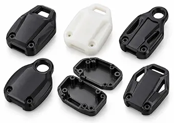
A lightweight non-metallic option for functional supports, insulation needs or designs where a metal exterior is not required.
Plastic CNC machining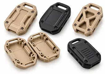
A specialized engineering plastic for projects requiring higher thermal, chemical or functional performance.
Engineering plastic machining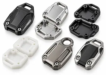
Other machinable metals or engineering plastics can be reviewed according to your mechanical, environmental, cosmetic and cost requirements.
Typical values below are engineering reference values only; final alloy grade, heat condition, finish and supplier certification should be confirmed during DFM and quotation.
| Product Priority | Material Direction | Key Engineering Considerations | Typical Finish / Design Value |
|---|---|---|---|
| Lightweight + anodized color | 6061-T6 / 7075-T6 Aluminum | 6061-T6 is about 2.70 g/cm³ with ~69 GPa elastic modulus; 7075-T6 is about 2.81 g/cm³ with ~72 GPa modulus. We review wall thickness, blade-seat stiffness and material-removal balance before finalizing the route. | Type II / hard anodizing, bead blast + anodize, polishing + anodize; strong color flexibility with low weight and visible machined-metal character. |
| Higher rigidity + premium metal feel | Stainless Steel | Typical austenitic grades are around 7.9–8.0 g/cm³ and ~190+ GPa elastic modulus. We review work hardening, small-thread quality, burr control and the higher cutting load around thin sections. | Brushing, polishing, passivation, electropolishing, PVD / DLC; heavier tactile feel, durable edges and premium bare-metal appearance. |
| High strength-to-weight + premium positioning | Titanium Grade 5 | Density is about 4.43 g/cm³ and elastic modulus about 114 GPa. Heat control, tool engagement and small-feature strategy matter because titanium is less forgiving than aluminum during compact precision machining. | Bead blasting, polishing, laser marking, selected PVD / DLC; premium material identity with lower weight than steel. |
| Decorative natural metal appearance | Brass | C360 brass is around 8.49 g/cm³ with good fine-feature machinability. We still review small threads, insert geometry and edge protection because the higher mass changes product feel and handling. | Polishing, brushing, nickel / chrome plating, selected PVD; warm metallic appearance and distinctive tactile weight for premium / EDC designs. |
| Low-mass non-metallic functional support | POM | Typical density is about 1.41 g/cm³ with much lower stiffness than metal. We account for clamping force, wall flexibility, temperature and load before using plastic as a locating or structural feature. | Usually used in the machined material state with laser / application-specific marking; low weight, electrical insulation and low-friction functional support. |
| Higher-performance engineering plastic | PEEK | Typical density is about 1.30 g/cm³ with higher thermal and chemical capability than general engineering plastics. We review actual service temperature, load and dimensional stability before selection. | Usually left in base material condition; high-value functional solution when temperature, chemical resistance or insulation matters more than cosmetic metal appearance. |
Surface finishing affects appearance, tactile feel, wear behavior and sometimes critical fit. Machining and finishing should therefore be planned together, especially when the product has visible A-surfaces and assembly-critical interfaces.
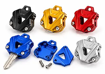
Decorative color and corrosion protection for aluminum key head covers, with critical interfaces reviewed before finishing.
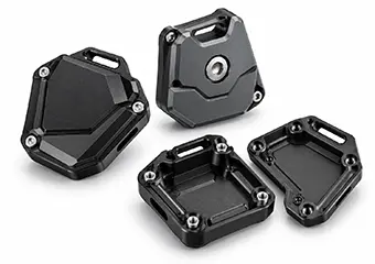
Useful where surface hardness and wear resistance are more important than decorative color flexibility.
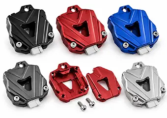
Creates a uniform matte appearance and supports premium colored aluminum accessories.
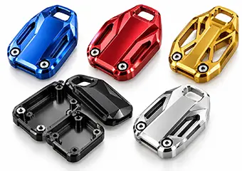
Supports brighter, smoother aluminum surfaces while retaining anodized color and protection, usually for designs seeking a more reflective premium look.
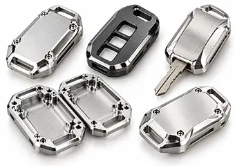
Creates directional or reflective metallic appearances on suitable aluminum, stainless steel, titanium or brass designs where tactile feel also matters.
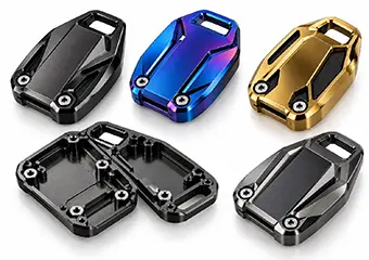
Can provide distinctive appearance and functional surface characteristics on suitable substrates and coating systems when the project needs stronger finish positioning.
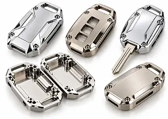
Supports bright metallic cosmetic finishes on suitable materials while requiring review of build-up and fit areas before the process is approved.
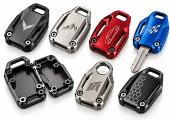
Adds logos, model information or graphics while integrating the marking position with the final surface finish and the part’s visible design layout.
A successful prototype should prove blade fit, assembly, fastening, edge condition and finished appearance — not simply confirm that one part can be machined.
Check insertion, location, retention and clearance against the drawing or approved reference before larger quantities are produced.
Confirm housing closure, mating alignment, screw position and thread engagement as a complete assembly.
Review color, texture, marking and selected post-finish dimensions where secondary processing can affect assembly.
Approved drawing revision, datums, fixture concept, machining sequence, finish requirements and inspection points become the production reference.
We support proprietary geometry, material, finish, branding and attachment features based on your product design, drawing and approved sample.
Custom faces, grooves, pockets, skeletonized windows and profile language.
Aluminum, stainless steel, titanium, brass or plastics selected around product value and function.
Matte, polished, brushed, anodized, plated or coated appearance requirements integrated into the process.
Laser marking or engraving for logos, model names, serial information and decorative graphics.
Key-ring holes, slots and integrated connection structures can become part of the machined body.
Visible areas are defined early so workholding, finishing, inspection and packaging focus on the correct surfaces.
Quality control should verify the features that determine real product performance: blade fit, mating alignment, fastening, finished appearance and repeat assembly. We build the inspection plan around how the key head cover actually works, rather than treating quality as a final measurement step only.
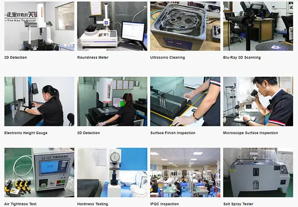
Custom machined key heads are used when standard molded or retail designs do not meet the required geometry, material, appearance, durability or brand positioning.
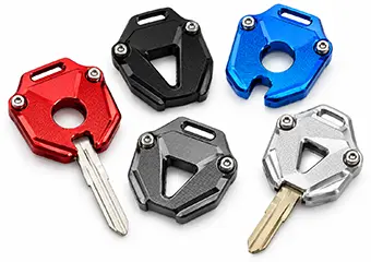
Motorcycle and powersports brands use CNC key head covers, blade holders and attachment structures to improve fit durability, premium appearance and recognizable aftermarket product identity.
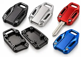
Automotive and mobility applications use custom mechanical key heads and machined housings to improve blade fit, assembly consistency, surface quality and long-term handling durability.
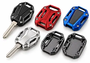
Performance and motorsport products use lightweight machined key head structures and premium finishes to reduce excess mass while strengthening a technical, performance-focused brand image.
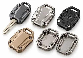
Premium EDC and lifestyle accessories use machined key head bodies and decorative components to deliver distinctive material feel, cleaner detailing and higher perceived product value.
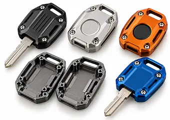
Industrial equipment and machinery use robust machined mechanical key heads and support parts to improve identification, handling durability and repeatable fit in daily operating environments.
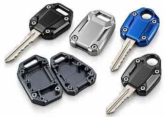
Access control and security hardware systems use custom mechanical key head structures to support reliable fit, stronger handling durability, clear identification and flexible OEM branding.
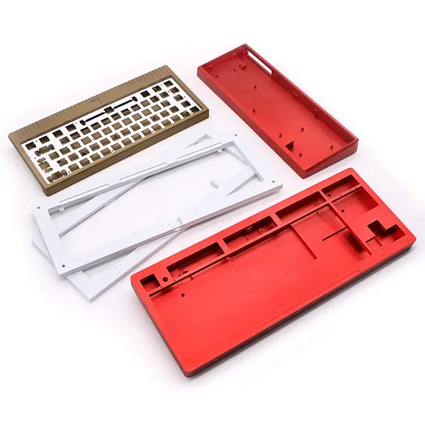
Customer requirement: this mechanical keyboard shell was developed for a mid-to-high-end product, so the customer placed strict requirements on the visible aluminum surface. We reviewed the material, fixtures, cutting strategy and surface-preparation steps together instead of treating anodizing as a separate finishing operation.
Material and machining strategy: for the required 200# sandblasted finish, we selected AL6063 for the case. During machining optimization, changing the cutter strategy increased the Z-axis feed efficiency by about 30%. We also reduced unnecessary toolpath joints, adjusted the R-angle strategy and used a PCD finishing tool to reduce visible machining and joint marks.
Pre-finish surface control: before anodizing, we manually treated sharp edges with a 400# sponge and cleaned the semi-finished parts with pure water to reduce the risk of cutting-fluid contamination and surface defects. For parts requiring painting or electrophoresis, additional polishing was used to improve surface preparation and coating adhesion.
Customer result: after receiving the finished keyboard, the customer confirmed they were very happy with the product quality and asked about placing another order. This case shows how we coordinate machining efficiency, cosmetic surface control and pre-finish preparation when a visible aluminum housing has demanding appearance requirements.
Our customers trust us because we communicate clearly, solve problems during sampling, deliver parts that meet the agreed quality level, and protect finished products through packing and shipment. The comments below are real examples of what customers told us after completed projects.
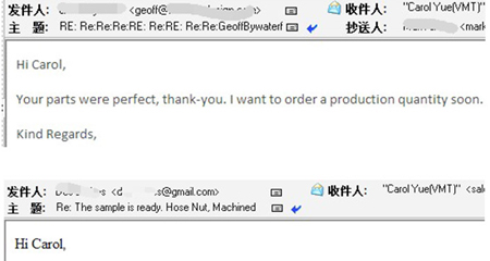
“Your quote is very good. I am working with my customer; if he approves my quote I will have other work that I will need you to quote on.”
Clear quotation support and responsive communication help customers keep moving internally and give us the opportunity to support the next project.
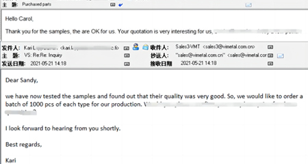
“We have now tested the samples and found out that their quality was very good. So, we would like to order a batch of 1000 pcs of each type for our production.”
This is the outcome we want from prototype work: the customer validates the samples, gains confidence in the quality, and can move into a real production order.
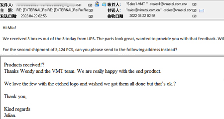
“Products received! Thanks Wendy and the VMT team. We are really happy with the end product. We love the few with the etched logo…”
The customer is judging the final delivered product, not only our machining. Surface appearance, marking and overall presentation all contribute to whether the project feels successful.
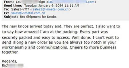
“The new parts arrived today and they are perfect… I was amazed at the packing. Every part was securely packed and easy to access.”
Good parts can still be damaged after inspection, so we treat protective packing and shipment as part of the manufacturing result, especially for anodized, polished and other cosmetic parts.
A complete RFQ helps VMT evaluate machining, material, finishing, inspection and production requirements more accurately. If your project is still under development, send the information you already have first.
| Information | What to Send | Why It Matters |
|---|---|---|
| 3D CAD Model | STEP / STP / IGES | Geometry and machining review |
| 2D Drawing | PDF / DWG | Tolerances, threads and manufacturing notes |
| Physical Key / Sample | Sample / photos / dimensions | Blade-interface reference |
| Material | Grade or performance requirement | Machining and cost planning |
| Surface Finish | Process / color / texture | Cosmetic and fit planning |
| Logo / Branding | Vector artwork | Marking and appearance review |
| Quantity | Prototype + expected production | Fixture and manufacturing strategy |
| Critical Features | Marked drawing notes | Inspection planning |
| Assembly Information | Mating method / related parts | Fit and tolerance review |
| Cosmetic Requirements | A-surfaces / reference sample | Appearance control |
Use this guide to review the main design, machining, material, finishing, validation and RFQ decisions that determine whether a custom key head cover is easy to manufacture, assemble and repeat.
We recommend defining the blade interface before spending too much time on the outer styling. Slot width, insertion depth, locating faces and retention geometry determine whether the key can be installed correctly and whether the housing will feel stable in use. If those functional features are vague, the sample may still look good in CAD but require repeated hand fitting after machining.
We use the blade interface to establish the main functional datums, then check how screw locations, mating faces and the outside profile relate to those datums. This gives the project a clearer measurement strategy and helps prevent a cosmetic redesign from accidentally moving the features that control real fit.
Two housings can both pass individual inspection and still produce a poor assembled result if the mating datums are not planned as a system. Typical problems include an uneven split line, a visible step between the upper and lower shell, screw holes that pull the cover sideways, or a blade that sits correctly in one half but becomes tight after the second half is installed.
We review mating faces, locating steps, closure direction, screw position and exterior profile together. First-article and assembly checks then confirm that the measured dimensions translate into the assembled condition the customer actually sees. This reduces the risk of approving “good parts” that create a bad product when assembled.
Material choice affects more than strength. It changes the weight in the customer’s hand, machining stability, achievable wall thickness, thread behavior, surface finish options and the cost of repeat production. 6061 aluminum is often a practical starting point for colored anodized designs, while 7075 may suit thinner performance structures, stainless steel provides a denser premium feel, titanium supports high-value lightweight products, and POM / PEEK can solve non-metallic functional needs.
We compare the material against the actual blade-seat geometry, wall thickness, finish, expected quantity and target product positioning before recommending a route. This prevents a material from being selected only because it sounds “premium” while creating unnecessary machining or finishing risk.
Skeletonized key heads, deep pockets and narrow ribs can reduce weight and create a strong visual identity, but every pocket also removes support from the part during machining. The remaining wall may move under cutting force or clamping pressure, especially after roughing removes the material that initially kept the blank rigid.
We review unsupported wall length, pocket depth, internal radius, material choice and clamping strategy before production. Staged roughing and finishing, controlled workholding and suitable tool engagement help keep the structure more stable. The goal is not to make the part heavier; it is to preserve the lightweight design without creating avoidable distortion or poor cosmetic edges.
Small key head covers leave very little space for threads, counterbores and driver access. A screw may fit inside the CAD model but still be difficult to manufacture if the thread is too close to the outer wall, the counterbore weakens a thin boss, or the driver cannot approach the fastener cleanly during assembly.
We review thread depth, edge distance, counterbore size, tool access, surrounding material and the assembly direction during DFM. Critical threaded features can be checked with suitable gauges, while hole positions can be tied back to common datums. This helps reduce stripped threads, cross-threading and covers that only close when the screws are forced into place.
Surface finish is part of the dimensional plan, not a decision to make after machining is complete. Anodizing, plating, polishing and PVD can change the surface condition, edge appearance or effective fit of blade slots, mating faces and threaded areas. A blank can pass inspection and still become difficult to assemble after finishing if the critical interfaces were never identified.
We review the finish together with the material and critical features, then decide whether an area needs allowance, masking, protected threads or post-finish reinspection. Designated finished-condition dimensions can be inspected 100%, which gives the customer confidence in the part that will actually be assembled rather than only in the unfinished machined blank.
Not every surface on the part needs the same cosmetic standard. The customer usually cares most about the faces and edges seen or touched after assembly, while hidden pockets or internal features may only need to meet function. If A-surfaces are not identified early, fixtures, deburring and handling can accidentally place marks exactly where the end user will notice them.
We mark the visible faces during process planning and coordinate toolpath, fixture contact, deburring, surface treatment, appearance inspection and packaging around those areas. Critical appearance points can be inspected 100% to the agreed standard, helping us protect the visual quality that justifies a premium machined product.
A useful prototype should answer practical questions: does the blade insert and locate correctly, do both housings close without forcing, do the screws engage smoothly, are the edges comfortable to handle, and does the final finish look like the product the customer wants to sell? Checking only the machined dimensions is not enough if the assembled experience is wrong.
We use prototype feedback to lock the functional datums, assembly relationship, finish reference and critical inspection points before repeat production. After approval, those decisions become the basis for fixtures, IPQC, finished-condition checks and packaging, so the production batch is aimed at reproducing the approved sample condition rather than simply re-running the same program.
Cost is usually driven by more than the amount of metal in the part. The number of setups, amount of material removal, small internal radii, deep pockets, tight tolerances, thread quantity, finish complexity and cosmetic acceptance level can all add machining or inspection time. A low-volume prototype also carries setup time differently from a repeat production batch.
During DFM, we separate the features that are truly functional from the features that are only adding process complexity. If a tight tolerance, tiny radius or complex finish boundary does not create real product value, we can point it out for discussion. The goal is not to make the product “cheaper at any cost”; it is to spend manufacturing effort where the customer will actually benefit from it.
The fastest quotation comes from clear project context, not from sending a 3D model alone. We can work from CAD, drawings, photos or a physical sample, but the RFQ becomes much more useful when it also includes material preference, finish, expected quantity, blade information, assembly method, critical dimensions and cosmetic requirements.
If some of that information is not ready yet, send what you have. We can identify the missing items during review and tell you which details affect manufacturing, cost or inspection. That reduces repeated back-and-forth and gives both sides a clearer path from quotation to sample approval and repeat production.
Whether you are developing a new motorcycle key head cover, replacing a molded key head with a machined design, validating a prototype or preparing for repeat production, VMT can review your drawing, sample, material, finish and assembly requirements before quotation.
No standard product selection is required — VMT manufactures custom key head covers based on your project requirements.
Useful information: CAD / Drawing · Sample or Key Dimensions · Material · Finish · Quantity · Assembly Requirements
 Related suggestion
Give us a call or send an inquiry to our emailbox, we will answer your doubts according to your customers' requirements, and quote you immediately.
Ready To Start Your Next Project?
Get Instant Quote


 +86 15099911516



Request a Free Quote
Send us a message if you have any questions or request a quote. We will get back to you ASAP!