16 years one-stop China custom CNC machining parts factory

Hey there I’m VMT Sam!
With 25 years of CNC machining experience we are committed to helping clients overcome 10000 complex part-processing challenges all to contribute to a better life through intelligent manufacturing. Contact us now
 97 |
Published by VMT at May 26 2026 | Reading Time:About 2 minutes
97 |
Published by VMT at May 26 2026 | Reading Time:About 2 minutes


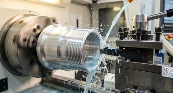
While conventional manufacturing methods fall short of ultra-precision requirements, advanced CNC machining successfully rises to the challenge. By leveraging ultra-precision CNC machining to achieve the integrated, single-setting fabrication of optical lens seats and barrels with a concentricity of <5µm, mechanical alignment is inherently guaranteed during assembly. Crucially, this eliminates any adverse downstream impacts on optical centration.
For high-precision optical systems—such as automotive lenses, medical endoscopes, and semiconductor inspection equipment—the tolerances for both mechanical concentricity and optical centration (which is heavily dictated by mechanical precision) are exceptionally stringent. Mastering the methodologies to control concentricity within <5µm in multi-element assemblies will not only provide you with robust engineering design references but also establish a definitive benchmark when defining production requirements for custom component suppliers. At the very end, we will also share a case study of how our factory achieved <5µm concentricity for a custom complex optical component for our clients.
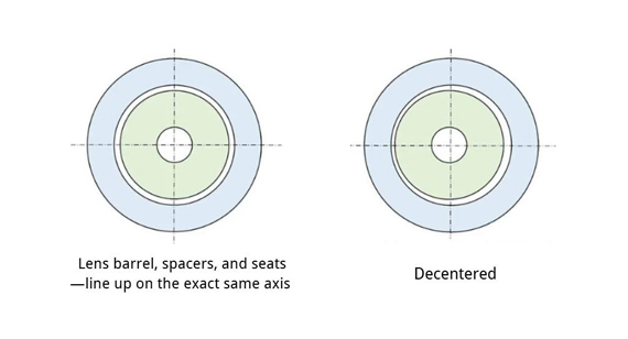
Let’s clear up two terms that often get mixed up. Think of them as cause and effect. Concentricity is a mechanical measurement. It tells you whether the physical centers of your parts—like the lens barrel, spacers, and seats—line up on the exact same axis. Centration error, on the other hand, is an optical measurement. It refers to how much the glass lens itself tilts or shifts off-center. Simply put: if your mechanical concentricity is off (the cause), your optical lenses will inevitably be decentered (the effect).
If your structural parts miss that sub-5µm concentricity, the glass elements inside will start to tilt or shift. When light passes through these misaligned lenses, it can no longer focus cleanly on the sensor. Let’s take some concrete examples:
Poor Effects
If you are testing the lens or looking at the final image, poor concentricity will show up as very obvious defects:
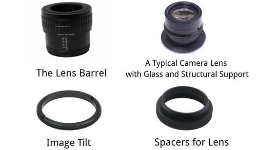
It is not only the polished glass elements composed of optical lens assembly, but also the structural optical components such as lens barrels, spacers, and image tilt work together with glass lenses.
The Foundation of Your Sub-5µm Goal
Here is the most critical takeaway for your design: the geometric tolerances of these mechanical parts are the absolute foundation of your final concentricity. Think about it—if the inner wall of the lens barrel is slightly tapered, or if a spacer is microscopically thicker on one side than the other, your lenses will tilt. No matter how perfect your glass elements are, a single poorly machined mechanical part will damage the alignment of the whole assembly.
Step 1: The Design Stage — Please Mark the Ultra-Precision Areas on the Drawing
At this point, physical production has not yet begun; the focus is generally on specifying and marking the accuracy requirements for the parts on the drawings. You need to consider: "If this part's accuracy deviates by 2 microns, will the image blur? If that part's accuracy deviates by 5 microns, will the entire lens assembly fail to meet requirements, leading to a complete rework?
Of course, if you are in a position where the budget is highly abundant, demanding a 5-micron tolerance for all areas is also acceptable. But if you want better production efficiency and cost effectiveness, please ensure the most critical components and mating surfaces with tight tolerance requirements are identified, and establish strict standards for them in the drawing.
Step 2: The Manufacturing Stage — CNC Machining Must Meet Geometric Tolerances and Accuracy
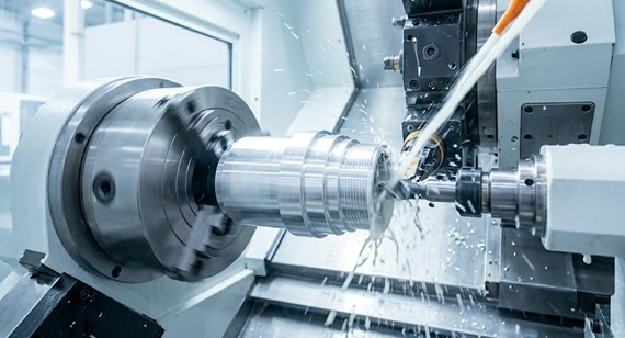
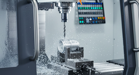
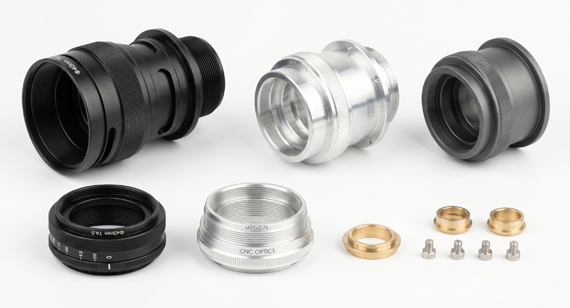
Once the drawings are ready, it relies on ultra-precision CNC machines to produce components like lens barrels and spacers. This is done by cutting, turning, grinding, and drilling a solid block of material (such as aluminum or brass) to remove excess material and obtain the final part. If this step is not executed properly, and the machined surfaces deviate from the drawing requirements, or the thin-walled sections of the component end up with uneven thickness, the part can essentially be considered completely unusable.
Step 3: The Assembly Stage — Passive Assembly vs. Active Alignment
Now that the parts are all made, how are the glass lenses placed inside? Two methods can be recommended here:
Beside from designing and carefully machining the key interface of optical parts with tight tolerance and accurate geometric tolerance, here are another two advanced tips for managing lens component concentricity:
Matching the Coefficient of Thermal Expansion (CTE) of Materials
When selecting materials—such as aluminum 6061, titanium, or stainless steel—please pay attention to their coefficient of thermal expansion (CTE). Different materials expand and contract at different rates when temperatures change. If the glass lens (made of regular glass, sapphire glass, or infrared glass) and the metal housing (like the lens barrel) expand unevenly, it can create internal stress or gaps, causing the sub-5µm concentricity to shift during operation. Therefore, choosing a metal with a CTE that closely matches the glass elements is a critical design step to maintain stability across varying temperatures.
Accounting for the Microscopic Impact and Allowance of Surface Treatments
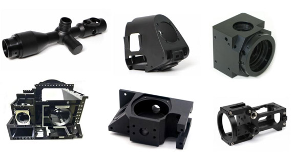
Surface treatments, such as anodizing, or black oxidation, are often required for optical components, but they always introduce a slight change in physical dimensions. For example, the anodizing actually grows a microscopic layer on the metal surface—If this thickness is not factored into the initial CNC machining drawings, the final parts will not fit perfectly during assembly. To avoid this, a precise dimensional allowance must be reserved during the machining stage, ensuring that the parts hit the exact target dimensions after the surface treatment is completed.
High-Precision CNC Machining for Camera Lens Ring Enclosures
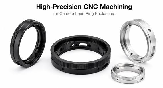
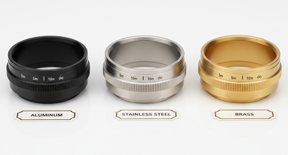
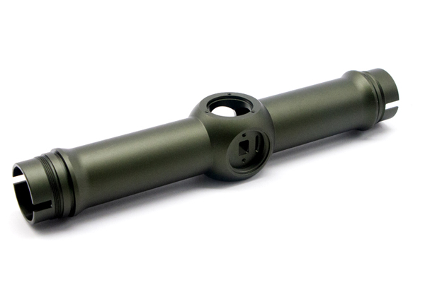
A client approached us with a high-precision optical project requiring the manufacturing of a batch of custom camera lens ring enclosures. The component featured multiple internal steps and bores, and the coaxially/concentricity across all these distinct steps had to be strictly controlled within 5µm. The client needed a manufacturing partner capable of repeatedly hitting these near-zero margins of error.
To tackle this extreme precision requirement, our engineering team developed a rigorous production strategy. The core of the solution was a custom-designed fixture that allowed for single-setting machining. By securing the material and machining all the critical internal bores, steps, and mating faces in a single setup on our ultra-precision CNC machines, we completely prevented the cumulative errors caused by re-clamping. Following production, the parts were verified using high-end metrology tools, including Coordinate Measuring Machines (CMM) and specialized air gauges, to guarantee that parts’ dimensions are aligned with the technical prints.
Through strict process control and optimized fixture engineering, we successfully delivered the batch of camera lens ring enclosures with a 100% pass rate. The final components flawlessly met the sub-5µm concentricity benchmark, ensuring that the glass lens elements aligned perfectly upon final assembly. The client reported that the optical system achieved its exact expected imaging quality, completely free of asymmetric aberrations, and willing to keep a long-term cooperation with us.
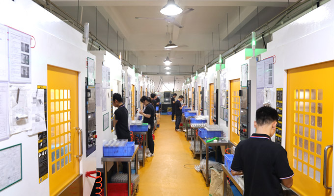
By prioritizing geometric tolerances at the design stage, leveraging single-setting ultra-precision CNC machining, and accounting for the microscopic realities of surface treatments and thermal behavior, you turn a high-stakes engineering challenge into a repeatable, predictable manufacturing process.
This blog has introduced the essential technical framework and manufacturing methodologies required to control concentricity within <5µm, so you can design high-performance optical systems with total baseline predictability and establish referenced quality standards for your custom component suppliers.
Ready to prevent centration errors and elevate your optical alignment? Contact engineering team at VMT today to submit your drawings of custom parts' manufacturing with ±5µm tolerances.
【For learning about more comprehensive information about camera lens parts manufacturing, welcome to click and read our technical white paper: The Ultimate Guide to High-Precision Camera Lens Parts Manufacturing. 】

Why is Aluminum 6061-T6 favored for optical housings?
This alloy is highly stable, cost-effective, and machines beautifully to tight tolerances. It also has good strength, corrosion resistance, and lightweight properties. Anyway, you can choose the aluminum 6061-t6 for structural optical housings with the above properties and cost-effective advantage.
How does tool wear affect sub-5µm tolerances during a production run?
Microscopic tool wear during long CNC machining runs can cause dimensions to drift by several microns. To counter this, ultra-precision factories use diamond or diamond-like carbon (DLC) coated cutting tools, perform real-time in-machine probing, and implement automatic tool offsets to maintain consistency.
How do you prevent UV adhesive shrinkage from ruining concentricity during assembly?
During active alignment, the volumetric shrinkage of UV-cure optical epoxies can pull the lens element out of alignment as it hardens. To mitigate this, you can use low-shrinkage adhesives, apply the glue symmetrically in microscopic increments, and utilize optimized UV-light curing profiles to evenly distribute mechanical stress.
What role does cylindricity play in maintaining multi-element lens alignment?
Cylindricity ensures that the internal bore of the lens barrel is a perfect cylinder, free of tapering or "hourglassing" from top to bottom. If cylindricity is poor, spacers and lenses will tilt or jam as they are slid down into the barrel, completely derailing your <5µm concentricity goal before the retaining ring is even tightened.
How do you accurately measure and verify sub-5µm concentricity in a production environment?
Verifying sub-5µm concentricity requires advanced metrology equipment to eliminate measurement uncertainty. Microscopic deviations are typically verified using Coordinate Measuring Machines (CMM) equipped with ultra-sensitive scanning probes, non-contact laser confocal systems, or specialized air gauges. Additionally, factories often use custom concentricity test fixtures with precision mandrels to rotate the part and capture real-time indicator readings.
How does retaining ring tightening torque impact the final lens alignment?
Overtightening or unevenly applying torque to the retaining ring can introduce structural stress, causing the internal spacers to warp and the glass elements to tilt. To safeguard the <5µm concentricity target, it’s best to use calibrated torque wrenches and specify fine-pitch threads to ensure even, controlled downward pressure without shifting the components.
The technical information and manufacturing advice shared on the VMT website are for general guidance only. While we strive for accuracy, VMT does not guarantee that the processes, tolerances, or material properties mentioned are applicable to every specific project. Any reliance you place on such information is strictly at your own risk. It is the buyer's responsibility to provide definitive engineering specifications for any production orders. Final specifications and service terms shall be subject to the formal contract or quotation confirmed by both parties.


 +86 15099911516




 Read more