16 years one-stop China custom CNC machining parts factory

Hey there I’m VMT Sam!
With 25 years of CNC machining experience we are committed to helping clients overcome 10000 complex part-processing challenges all to contribute to a better life through intelligent manufacturing. Contact us now
 84 |
Published by VMT at May 25 2026 | Reading Time:About 2 minutes
84 |
Published by VMT at May 25 2026 | Reading Time:About 2 minutes


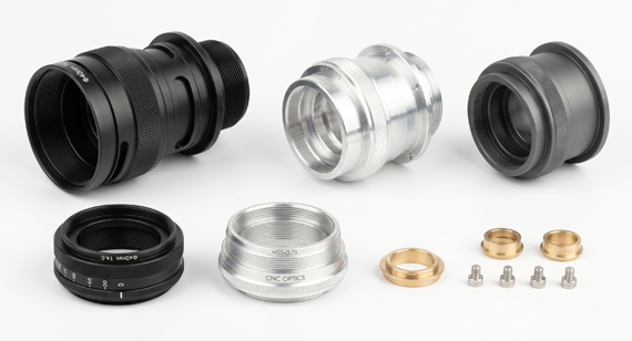
When it comes to lens barrel—it is a necessary component used in smartphone camera modules, automotive lenses, or machine vision. As one big category of camera lens parts, lens barrels definitely play the role of protecting and precisely positioning the lenses.
But how should the centration and coaxiality of the lenses after assembly be ensured? What you should understand, of course, is how to achieve a precision tolerance of ± 5μm for the lens barrel inner diameter (ID). Only in this way can you directly avoid assembly inaccuracy that leads to lens tilt or eccentricity, which in turn causes chromatic aberration, astigmatism, and other user experiences that the end consumers dislike.
This article will center around the core of lens barrel ID machining and lens centration control, breaking down the critical control points from roughing to finishing for you, and sharing our factory machining case study at the end of the text. If you want to know how to consistently achieve a ± 5μm ID tolerance and perfectly control lens centration in CNC precision machining by optimizing tools, fixtures, and machining processes, this guide is for you.
First and foremost, we need to clarify that CNC machining is one of the premier manufacturing processes capable of achieving the highest possible fidelity from design blueprints to actual production. This means that through high-precision CNC machining, you can ensure that the dimensions of the physically manufactured lens barrel deviate from the theoretical design values by a mere ± 5μm (or 0.005mm).
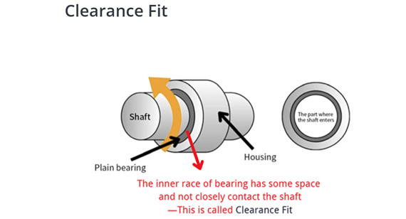
In actual lens module assembly, the relation between the lens barrel ID and the lens Outer Diameter (OD) is a tight clearance fit. When the lens barrel ID tolerance is poorly controlled and runs too large, this clearance gap increases. Consequently, during drop-in assembly, the lens can undergo unpredictable lateral displacement or subtle tilting inside the barrel before it is permanently bonded. In optical design, this micron-level physical shift is amplified across multiple lens layers, directly causing the optical axes of the lenses to misalign.
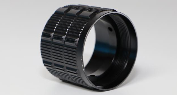
Beyond absolute dimensional tolerance, geometric tolerances are also important. This means that not only must the ID dimension tightly hold, but its cylindricity and coaxiality must also reach micron-level precision. If the machining process is unstable, causing the ID to become microscopically "oval-shaped" or "tapered," the barrel wall will exert uneven, localized stress on the lens edges during lens placement and alignment. This internal stress causes microscopic surface deformations on the lens, triggering astigmatism, coma, and other optical defects.
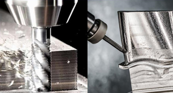
To consistently hit a ± 5μm inner diameter (ID) tolerance on a lens barrel, you cannot rely solely on the final finishing pass. It requires a highly systematic, multi-stage CNC machining strategy. Each phase—from initial heavy material removal to the final micro-cuts—plays a distinct role in ensuring dimensional stability and mitigating material deformation. To provide a clear overview of how this process unfolds, the table below outlines the primary objectives, core control factors, and recommended machining allowances for each stage:
| Machining Stage |
Primary Objective |
Control |
Recommended Allowance |
| Roughing |
Efficiently remove the bulk of the material | Relieve internal stress; prevent thermal deformation | Leave an allowance of 0.2 to 0.3 mm |
| Semi-Finishing |
Correct geometric distortions and prepare for finishing | Control roundness and step pitch; stabilize dimensions | Leave an allowance of 0.03 to 0.05 mm |
| Finishing |
Secure the final ± 5μm tolerance and pristine surface finish | Fine-adjustment boring bars; constant temperature control; micron-level cutting edge compensation | Target / Final Dimension |
Top Tips for Machining Lens Barrel
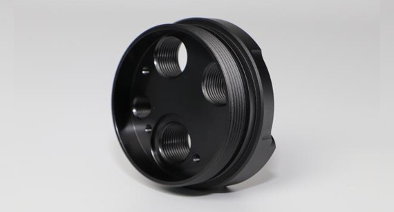
Stress Relief: Most high-precision lens barrels are machined from lightweight aluminum alloys such as 6061 or 7075, or copper and brass. During roughing, rapid material removal generates much cutting heat— this will cause the component to "shrink" or warp over time if you transition immediately to the finishing stage. Therefore, you'd better implement a strict stress-relief protocol—such as artificial aging or an extended stabilization period—after roughing to allow the material to settle completely before further processing.
Semi-Finishing: Its main job is to correct the geometric and form errors (such as slight waviness or out-of-roundness) left behind by heavy roughing. You can establish a highly uniform and precise machining allowance (0.03–0.05 mm) to ensure that the finishing tool encounters perfectly consistent cutting forces.
Finishing by Single-Point Boring: Single-point fine boring establishes a brand-new cutting axis based entirely on the machine spindle. Choosing this can minimize radial cutting forces, offering unmatched control over coaxiality and roundness to ensure the final ID is perfectly true.
If the manufacturing processes can be optimized to achieve both high speed and flawless quality in lens barrel mass production—you will surely benefit from faster delivery times and optimized cost saving. Let’s take a look at how this is achieved:
Tooling Optimization to Reduce Tool Wear and Accelerate Production
For cutting tools, we highly recommend using PCD (Polycrystalline Diamond) or ultra-fine grained carbide tools to ensure the excellent sharp cutting edge.
In mass production, a sub-micron level of tool wear will cause dimensions to drift outside the ± 5μm window. But PCD tools can offer high hardness and abrasion resistance. This can help reduce frequent tool changes—less spend on damaged cutting tools and accelerate Production.
Advanced Fixturing to Secure Thin-Walled Parts Without Deformation
Lens barrels are classic thin-walled parts. If the clamping force is too high, the part will deform during machining and turn into an "oval" shape once released. If it is too loose, cutting vibrations will ruin your precision requirements. But using diaphragm chucks, pie-shaped soft jaws, or custom hydraulic expansion mandrels can solve the issue. These fixtures distribute clamping pressure evenly across the entire 360-degree circumference—which help prevent physical distortion, ensure high roundness, and make loading and unloading parts much faster.
Strict Temperature Control to Defeat Thermal Expansion
Thermal expansion is a must factor if a ± 5μm needs to be achieved. Especially lens barrels made of aluminum—expands and contracts quickly with temperature changes. And a room shift of just a few degrees can cause the lens barrel ID to go completely out of spec. To stabilize mass production quality, climate-controlled at a constant 20±1℃ must be adhered to. Additionally, using a temperature-controlled, chilled coolant system is necessary. It instantly flushes away hot chips and keeps both the tool and the lens barrel at a stable thermal state, ensuring absolute dimensional consistency.
Mass-Produced high-precision Automotive Lens Barrels with Tight Tolerance
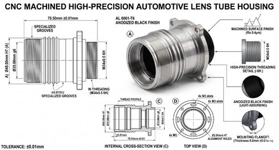
A brand manufacturer specializing in automotive lenses approached us with the blueprints for their latest new product. They needed us to mass-produce a highly sophisticated lens barrel. The part was designed with high-hardness aviation aluminum and featured multiple stepped internal diameter (ID) holes. To meet strict optical requirements, they explicitly demanded that the total tolerance of the lens barrel ID must be held within an incredibly tight ± 5μm.
When our engineering team reviewed the drawings, we immediately find the big problem: the wall thickness of the lens barrel was only 0.8mm, making it an extremely fragile, thin-walled part. Under conventional CNC setups, such a thin wall would easily warp or deform under the squeeze of standard chucks or the heat of cutting forces. What’s more, the clients required the lens centration error after the final assembly to be under 2μm. If the ID deformed even slightly, the lenses would tilt, negatively affecting the camera’s focus and image quality. We used custom PCD stepped boring bars to cut multiple internal features in a single pass, deployed a climate-controlled chilled coolant system to stop thermal expansion, and built a proprietary pneumatic expanding mandrel fixture to hold the part without any physical distortion.
The final results were outstanding: our process achieved a CPK of over 1.33, the first-pass yield rate reached 98.5%, and we perfectly prevented post-assembly issues of optical axis eccentricity and astigmatism.
Achieving and maintaining a strict ±5μm tolerance for lens barrel internal diameters isn't a very easy operation by plain CNC machining only. Every step is important—from the incremental relief of material stresses during roughing to the micron-precise balancing act of PCD tools, specialized diaphragm chucks, and a climate-controlled factory floor—must work in perfect harmony. Only when you grasp this critical control points can ensure perfect lens barrels with ultra-tight tolerance and precision geometric shapes. Or alternatively, just partner with a qualified and experienced CNC machining factory to achieve strict requirements for perfect lens barrels.
【For learning about more comprehensive information about camera lens parts manufacturing, welcome to click and read our technical white paper: The Ultimate Guide to High-Precision Camera Lens Parts Manufacturing.】

What inspection equipment is best suited for verifying a ±5μm lens barrel ID on the production floor?
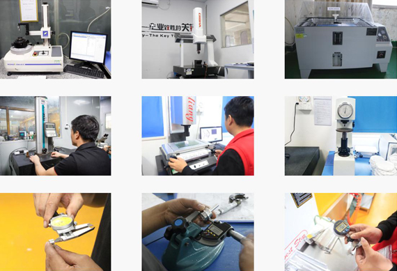
It is recommended to use pneumatic air gauging (air plugs) for rapid, high-precision ID measurements directly at the machine tool, as it offers sub-micron repeatability without scratching the delicate thin walls. For comprehensive geometric validation, a high-resolution coordinate measuring machine (CMM) or a dedicated roundness tester should be utilized in a temperature-controlled metrology lab to verify cylindricity and coaxiality.
How does surface roughness (Ra) impact the actual ID tolerance and lens assembly?
Surface finish and dimensional tolerance are deeply intertwined. For a ±5μm ID tolerance, the surface roughness should ideally be held to Ra 0.2 to 0.4μm. If the surface is too rough, lenses have potential to loosen, tilt, or shift over time, which damages the optical centration.
Does post-machining anodizing affect the ±5μm ID tolerance?
Yes: Anodizing grows a layer that reduces the internal diameter (e.g., a 10μm coating reduces the ID by about 10μm total). The engineering team must calculate this buildup in advance and machine the raw ID oversized to compensate.
What is the difference between coaxiality and concentricity here?
Why use aluminum 6061 or 7075, and what is the main challenge?
They offer excellent strength-to-weight ratio, great machinability, and clean, burr-free edges (especially 7075-T6)— excellent materials for lens barrels. But the biggest problem is that aluminum has a high thermal expansion rate. A room shift of just a few degrees will push the ID out of spec, making strict 20±1°C temperature control mandatory.
Can standard carbide tools work, or are PCD tools required?
The technical information and manufacturing advice shared on the VMT website are for general guidance only. While we strive for accuracy, VMT does not guarantee that the processes, tolerances, or material properties mentioned are applicable to every specific project. Any reliance you place on such information is strictly at your own risk. It is the buyer's responsibility to provide definitive engineering specifications for any production orders. Final specifications and service terms shall be subject to the formal contract or quotation confirmed by both parties.


 +86 15099911516




 Read more