16 years one-stop China custom CNC machining parts factory

Hey there I’m VMT Sam!
With 25 years of CNC machining experience we are committed to helping clients overcome 10000 complex part-processing challenges all to contribute to a better life through intelligent manufacturing. Contact us now
 2199 |
Published by VMT at Jul 24 2024
2199 |
Published by VMT at Jul 24 2024


In the field of CNC machining parts manufacturing, blind holes and through holes are two basic yet essential machining types widely used in circuit boards, mechanical parts, aerospace components, and more. This article will comprehensively explain the basic concepts, differences, manufacturing processes, design considerations, measurement and inspection techniques, and engineering applications of blind holes and through holes, aiming to provide readers with thorough and in-depth professional knowledge.
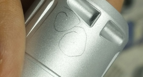
A blind hole is a hole that is drilled only from one side of a part and does not penetrate the entire thickness of the part. It is mainly used to connect the surface and internal layers of a part to achieve signal transmission or connection between specific layers. In contrast, a through hole is completely different; it penetrates the entire part from one end to the other and is commonly used for inserting pins, connectors, or electrical connections, providing mechanical support.

Summary: The main difference between blind holes and through holes lies in their structure and function. A blind hole does not penetrate the part and only connects specific layers, while a through hole completely penetrates the part and is used for electrical connections and mechanical support.
Symbols: In drawings and CAD designs, blind holes and through holes are usually represented by specific symbols for easy identification and differentiation. Blind holes are often represented by dashed circles, while through holes are depicted by solid circles.
Manufacturing Complexity: The manufacturing process for blind holes is relatively complex, requiring precise drilling depth and filling techniques. Through holes are comparatively simple, as they only need to penetrate the entire part.
Use Cases: Blind holes are often used in high-density interconnect and multilayer circuit board designs, such as in mobile phones and tablets. Through holes are widely used in industrial equipment and automotive electronics, where high strength and reliability are required.
Complexity: The design and manufacturing of blind holes require considering more factors, such as drilling depth and filling material selection. Through holes are relatively simple, mainly focusing on parameters like hole diameter and spacing.
Customization: Both blind holes and through holes can be customized according to specific needs, including hole diameter, depth, spacing, etc.
Alignment: In CNC machining, the alignment accuracy of blind holes and through holes is crucial. High-precision CNC equipment ensures the accurate positioning of the holes.
Summary: The machining of blind holes requires special attention to tolerances, surface finish, and material considerations to ensure machining quality and part performance.
Tolerance, Surface Finish, and Material Considerations: Tolerance control of blind holes directly affects the assembly accuracy and performance of parts. Surface finish impacts the corrosion resistance and signal transmission quality of the part. When selecting materials, factors such as material hardness, toughness, and machinability should be considered to ensure smooth processing of the blind hole.
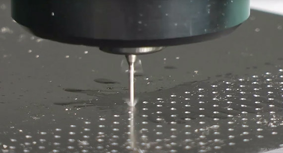
Blind Hole Cleaning and Drilling Techniques: After processing a blind hole, thorough cleaning is required to remove debris and impurities generated during drilling. Cleaning techniques include using compressed air, solvents, or special cleaning agents. Regarding drilling techniques, high-precision CNC equipment should be used to ensure precise control of drilling depth, hole diameter, and spacing.
Cleaning Techniques: When cleaning blind holes, avoid using hard tools or sharp objects to scrape the hole walls to prevent damaging the surface finish. It is recommended to use soft materials (e.g., cotton swabs, sponges) dipped in a suitable cleaning agent for wiping.
Placement and Guidance: The design of blind holes should fully consider the overall layout and functional requirements of the part. When placing blind holes, avoid interference with other parts or structures. Detailed design guidance should be provided to ensure machinists can accurately understand the design intent.
Tolerance, Surface Finish, and Material Considerations in Blind Hole Design: In the design of blind holes, the tolerance range, surface finish requirements, and material selection criteria should be clearly defined. These elements directly impact the machining quality and performance of the blind hole.
Precision CNC Blind Hole Drilling: Precision CNC blind hole drilling is key to achieving high-precision blind hole machining. During drilling, parameters such as feed rate, spindle speed, and cutting force of the drill bit should be strictly controlled to ensure drilling accuracy and surface quality.
Tapping Considerations in Blind Hole Design: If a blind hole requires tapping to install threaded connectors, this should be specially noted in the design. During tapping, select appropriate taps and tapping depths to avoid tap breakage or thread damage.
Power, Durability, and Heat: Through-hole components play an essential role in electrical connections and mechanical support on circuit boards. Their power handling capacity, durability, and thermal performance significantly affect the overall performance of the circuit board. When designing through-hole components, consider these factors to ensure the stable operation of the circuit board.
PCB Assembly Challenges and Solutions: During PCB assembly, the insertion and soldering of through-hole components are critical steps. However, the diversity and complexity of through-hole components may pose various challenges during assembly. To address these issues, automated assembly equipment, optimized soldering processes, and enhanced quality control measures can be adopted.
Design Considerations: CNC drilling design must fully consider factors such as the part's geometry, material properties, machining accuracy, and process requirements. During design, reasonably plan drilling paths, hole diameters, and spacing parameters to ensure machining efficiency and part quality.
CNC Drilling Design: CNC drilling design is a comprehensive process involving CAD drawing, CAM programming, and machine tool operation. In the CAD stage, designers need to accurately draw part drawings and mark all the required drilling positions and dimensions. Then, CAM software converts the CAD drawings into machine-readable codes, guiding the machine tool for precise drilling operations. The machine tool operator monitors the entire machining process to ensure the accuracy and efficiency of drilling.
Coordinated CNC Drilling Design: Coordination is key in CNC drilling design. Designers, programmers, and machine tool operators need to closely collaborate to ensure the design intent can be accurately conveyed and executed. Designers must provide detailed drilling requirements and drawings to programmers, who write efficient machining programs based on these requirements. Machine tool operators execute operations according to the programs and provide timely feedback on issues encountered during machining.
Calculation of Cutting Depth and Clearance: The calculation of cutting depth and clearance is crucial for CNC drilling design. Cutting depth determines the amount of material removed in each cut, and it must be determined based on material hardness, machine power, and tool durability. Clearance refers to the space between the drill bit and the hole wall, affecting drilling accuracy and surface quality. Proper cutting depth and clearance can improve machining efficiency, reduce tool wear, and ensure drilling accuracy and surface quality.
Quality Control Methods to Ensure Blind Hole Accuracy
To ensure the accuracy of blind holes, a series of quality control methods should be adopted. These methods include using precision measurement tools (e.g., bore gauges, microscopes) to measure the diameter, depth, and position of blind holes accurately; using coordinate measuring machines (CMMs) for three-dimensional coordinate measurement to verify their spatial position accuracy; and adopting non-destructive testing (NDT) techniques (e.g., X-rays, ultrasound) for internal inspection of blind holes to detect potential defects and issues.
Coordinate Measuring Machine (CMM): A coordinate measuring machine (CMM) is a high-precision three-dimensional measuring device capable of precisely measuring parts under computer control. In blind hole measurement, a CMM can measure parameters such as hole diameter, depth, position, and shape to ensure the machining accuracy of blind holes meets design requirements.
")
Surface Profilometer: A surface profilometer measures the contour shape and roughness of a part's surface. In blind hole measurement, it can be used to detect the surface finish of the hole walls, ensuring the surface quality of blind holes meets design requirements.
Non-Destructive Testing (NDT): Non-destructive testing (NDT) techniques can inspect the internal structure and defects of a part without damaging it. In blind hole measurement, NDT techniques can detect internal cracks, inclusions, and other defects, ensuring the quality and reliability of blind holes.
Measurement Tools and Inspection Processes: In addition to the advanced measurement equipment mentioned above, various measurement tools and inspection processes are needed to ensure the machining quality of blind and through holes. These tools include bore gauges, outside micrometers, vernier calipers, etc., used to measure basic parameters such as hole diameter and depth. Inspection processes include first article inspection, in-process inspection, and final inspection to ensure each machining step meets design requirements.

Focus on the Relevance of Blind and Through Holes in Machining: In CNC machining, the machining of blind and through holes is interrelated. They may be located on the same part and may need to cooperate to achieve specific functions. Therefore, during machining, special attention should be paid to their relevance, ensuring their position, dimensions, and accuracy meet design requirements.
Strictly Control Machining Parameters: Machining parameters are key factors affecting the machining quality of blind and through holes. During machining, cutting speed, feed rate, and cutting depth must be strictly controlled to ensure process stability and reliability.
Enhance Tool Management: Tools are essential in CNC machining, and their quality and condition directly impact machining results. Therefore, tool management must be enhanced, regularly inspecting and replacing severely worn tools to ensure tool sharpness and durability.
Purpose and Function: Blind and through holes have different purposes and functions in engineering. Blind holes are mainly used to connect the internal layers of parts or achieve signal transmission between specific layers, while through holes are primarily used for electrical connections, mechanical support, and fixation.
Materials: Various materials can be used in the machining of blind and through holes, including metals (e.g., aluminum, steel), plastics, ceramics, and composite materials. Different materials have different machining characteristics and process requirements.
Dimensions: The dimensions of blind and through holes, including diameter, depth, and spacing, are determined based on part design and functional requirements. Accurate control of these dimensions is crucial to ensure part performance and reliability.
Blind vias and through vias are widely used in multiple industries, including aerospace, automotive manufacturing, electronic equipment, medical devices, etc. In the aerospace field, blind vias and through vias are used to connect complex structural parts and transmit signals; in the automotive manufacturing field, they are used for electrical connections and cooling systems; in the electronic equipment field, blind vias and through vias have become key elements in circuit board design; in the medical device field, they are used to manufacture precision medical devices and implants.

In CNC machining, blind holes and through holes are crucial components, directly affecting the performance and quality of the final product. Understanding their differences, applications, and measurement techniques can provide better solutions for manufacturers and engineers. By adopting appropriate machining processes and quality control measures, manufacturers can ensure the accurate machining of blind and through holes, thus producing high-quality CNC machining parts.

What is a Blind Hole in CNC Machining?
A blind hole in CNC machining is a hole that is drilled from one side of a part without penetrating the entire thickness of the part. It is primarily used to connect the internal layers of a part or to achieve signal transmission between specific layers.
What is the Purpose of Blind Holes?
Blind holes have a wide range of applications in various fields. In electronic devices, blind holes are commonly used for connecting multilayer circuit boards. In mechanical manufacturing, blind holes can be used for mounting fasteners or achieving other specific mechanical connections.
What is the Symbol for Through Holes?
In drawings and CAD designs, through holes are typically represented by solid circles, with relevant information on hole diameter and spacing indicated.
What are the Differences Between Blind Holes and Through Holes?
The main differences between blind holes and through holes lie in their structure and function. A blind hole does not penetrate the part and only connects specific layers, while a through hole penetrates the entire part, serving purposes such as electrical connections and mechanical support.
What Tools are Used for Blind Holes?
The machining of blind holes typically employs specialized drill bits or milling cutters. Depending on the material and precision requirements, different types and shapes of drill bits or milling cutters may be chosen. Additionally, appropriate coolants and lubricants are necessary to ensure machining accuracy and surface quality.
Through this detailed explanation, it is hoped that readers can gain a deeper and more comprehensive understanding of blind holes and through holes. In the field of CNC machining parts manufacturing, mastering this basic knowledge will help improve work efficiency and product quality, driving continuous development and innovation in the industry.

 +86 15099911516


 Read more