16 years one-stop China custom CNC machining parts factory

Hey there I’m VMT Sam!
With 25 years of CNC machining experience we are committed to helping clients overcome 10000 complex part-processing challenges all to contribute to a better life through intelligent manufacturing. Contact us now
 1782 |
Published by VMT at Jun 23 2026 | Reading Time:About 2 minutes
1782 |
Published by VMT at Jun 23 2026 | Reading Time:About 2 minutes


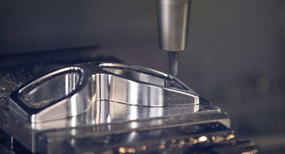
Gear is one of the indispensable parts of mechanical manufacturing. The main function of the wheel is to transmit power. Different gear combinations can play different roles. Acceleration, deceleration, and direction change are all possible. This article mainly talks about the relevant knowledge about gears.
A gear is a toothed wheel, which transmits the rotational motion of one shaft to another shaft by its meshing effect, and transmits motion or torsion between the two shafts. A gear is a mechanical element with teeth on the rim that can continuously mesh and transmit motion and power. Gears are toothed mechanical parts that can mesh with each other. The application of gears in transmission has appeared very early.
At the end of the 19th century, the principle of the generative gear cutting method and the special machine tools and tools that used this principle to cut gears appeared one after another. With the development of production, the smoothness of gear operation was paid attention to. Gears are used to change the direction of movement, increase or decrease the speed and output torque. Therefore, the gear transmission can easily change the speed, torque and direction of the power supply.
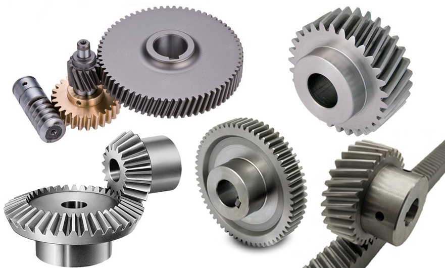
There are many types of gears, which are distinguished according to the gear axis.
According to the position of the shaft, gears can be divided into the following types. There are also categories of herringbone gears, internal gears, helical gears, hypoid gears, and more.
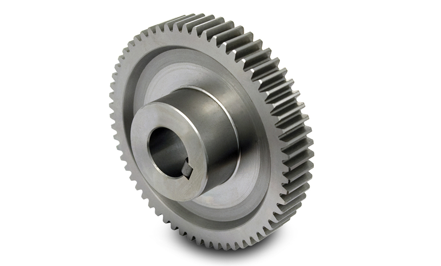
1. Spur Gear
The tooth profile contact line is a straight line parallel to the axis. A pair of tooth profiles enter or exit the mesh at the same time along the tooth width, which is easy to cause shock and noise, and the transmission stability is poor. Used to transfer power from one shaft to another parallel shaft, increasing or decreasing the torque of a given object. They are the most widely used gears and can achieve high precision and relatively easy and economical production processes. You can often find them in electric screwdrivers, oscillating nozzles, alarm clocks, washing machines, dryers, construction equipment, fuel pumps, and mills.
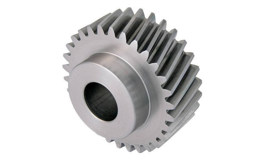
2. Helical Gear
The meshing process between the teeth of the helical cylindrical gear is an excessive process, and the force on the teeth gradually increases from small to large, and then from large to small; helical gears are suitable for high-speed and heavy-duty Condition. The increase in the degree of coincidence improves the load-bearing capacity of the gear. Thereby extending the life of the gear. The degree of coincidence mainly depends on the meshing time, and the meshing time of the helical gear is long and the contact area is large, which reduces the stress. And make the transmission stable, and increase its economy. Progressive meshing makes helical gears run more smoothly and quietly than spur gears. Therefore, they have better tooth meshing than spur gears and superior quietness. Helical gears can transmit higher loads, which makes them ideal for high-speed applications.
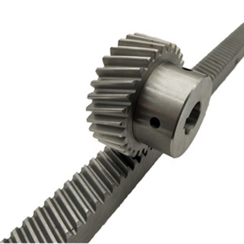
3. Rack and Pinion
Rack and pinion is a kind of gear, which includes a circular gear (pinion), which meshes with a linear gear (rack), and its function is to convert rotary motion into linear motion. The rack is a rack or rod. Drive the pinion to rotate to drive the rack linearly, and drive the rack to make the pinion rotate. Rack and pinion provide fewer mechanical advantages than other mechanisms such as recirculating balls. Speaking of the application of this kind of gear, an example is the automobile steering system, which converts the rotation of the steering wheel into the left-to-right movement of the lever.
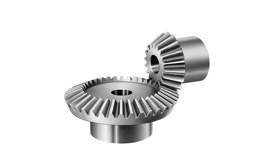
4. Bevel Gears
Bevel gears are used to transmit the movement and power between two intersecting shafts. In general machinery, the angle of intersection between the two shafts of bevel gears is equal to 90° (but not equal to 90°). Similar to cylindrical gears, bevel gears have indexing cones, addendum cones, tooth root cones and base cones. The cone has a big end and a small end, and the circle corresponding to the big end is called the index circle (its radius is r), the addendum circle, the root circle and the base circle.
The movement of a pair of bevel gears is equivalent to a pair of pitch cones as pure rolling bevel gears for differential transmission, which can transmit power to the two shafts to rotate at different speeds. It can also be used as the main mechanism of the handle drill. The bit handle rotates in the vertical direction. The bevel gear changes the rotation of the chuck to a horizontal rotation. The bevel gear and hand drill have the additional advantage of increasing the rotation speed of the chuck, making it possible to drill the range of materials.
Bevel gears are widely used, including locomotives, ships, automobiles, printing presses, cooling towers, power plants, steel mills, railway tracks, inspection machinery, etc.
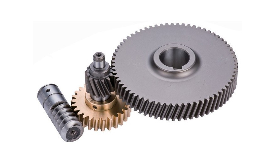
5. Worm and Worm Gear
The worm gear structure is often used to transmit the movement and power between two interleaved shafts. The worm wheel and the worm are equivalent to the gear and the rack in the middle plane, and the worm and the screw are similar in shape. In the form of a worm meshing with a worm gear, the shape of the worm is similar to that of a spur gear. These two elements are also called worm screws and worm gears. The terms are often confused due to the imprecise use of the terms. The same unit as other gears.
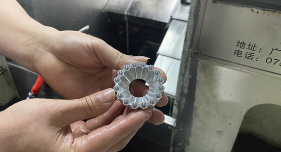
A machinery equipment manufacturer needed a custom precision gear for an industrial transmission system. The part had to maintain stable meshing performance, accurate tooth geometry, reliable concentricity, and long-term durability under repeated operation.

Project Challenge:
The customer’s original gear had noise issues during operation and uneven wear after long-term use. The key challenges included tooth accuracy, material strength, shaft hole concentricity, surface finish, and batch consistency.
VMT Solution:
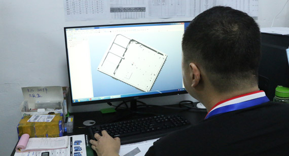
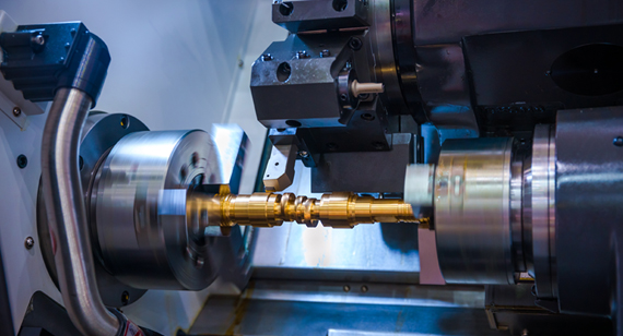
VMT reviewed the customer’s 2D drawings and 3D CAD files before production. Our engineering team evaluated the gear module, tooth profile, inner bore tolerance, keyway position, material selection, heat treatment requirements, and surface finishing needs.
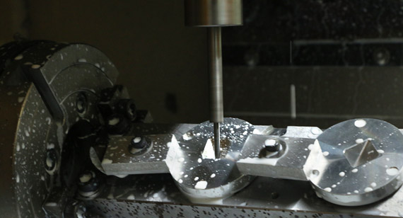
During machining, we controlled the critical dimensions of the tooth profile, inner hole, mounting surface, and shaft connection area. For high-precision gear applications, VMT also inspected key dimensions with professional measuring tools to help ensure stable assembly and reliable transmission performance.
Project Result:
The customer achieved smoother gear meshing, reduced assembly issues, improved wear resistance, and more stable performance in batch production. By combining CNC machining, process control, and quality inspection, VMT helped the customer reduce rework risk and improve product reliability.

Gears are essential mechanical components used to transmit power, change speed, adjust torque, and control motion direction. Different gear types, such as spur gears, helical gears, bevel gears, rack and pinion systems, and worm gears, are selected according to the transmission direction, load, speed, noise requirements, and application environment.
For engineers and OEM manufacturers, choosing the right gear type is only the first step. The final performance of a gear also depends on material selection, machining accuracy, tooth profile quality, concentricity, surface finish, heat treatment, and inspection control.
As a custom CNC machining manufacturer, VMT provides precision machining solutions for custom gears and related transmission components. Whether you need prototype gears, small-batch production, or mass production parts, we can support your project from drawing review and DFM feedback to machining, inspection, surface treatment, and final delivery.
If you are developing custom gear parts for industrial equipment, automation systems, robotics, automotive components, medical devices, or mechanical assemblies, you can send us your drawings for a fast engineering review and quotation.
Need Custom CNC Machined Gears for Your Project?
Send us your 2D drawings or 3D CAD files. VMT will review your gear design, evaluate machining feasibility, and provide a fast quote with practical manufacturing suggestions.

1. Can CNC machining be used to manufacture custom gears?
Yes. CNC machining can be used to manufacture custom gear blanks, gear-related shafts, mounting holes, keyways, gear housings, and some precision gear structures. For gears with special tooth profiles or high transmission requirements, CNC machining can also be combined with gear cutting, grinding, heat treatment, and surface finishing processes.
2. What information should I provide when requesting a custom gear quote?
To get an accurate quote, it is best to provide 2D drawings, 3D CAD files, material requirements, gear module or tooth specifications, tolerance requirements, surface treatment needs, quantity, and application environment. If the gear works with another mating gear, providing assembly information will help engineers better evaluate the fit and transmission performance.
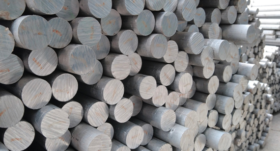
3. What materials are commonly used for CNC machined gears?
Common materials include carbon steel, alloy steel, stainless steel, brass, aluminum, bronze, and engineering plastics. The right material depends on load, speed, wear resistance, corrosion resistance, weight, noise control, and cost requirements.
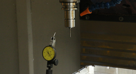
4. How do you control the accuracy of custom machined gears?
Gear accuracy is controlled through drawing review, machining process planning, proper clamping, tool selection, in-process inspection, and final quality control. For critical gear parts, key dimensions such as tooth profile, inner bore, concentricity, keyway position, mounting surface, and surface roughness should be carefully inspected.
5. Can you help optimize a gear design before production?
Yes. VMT can provide DFM suggestions before machining. If the gear design has risks such as difficult-to-machine features, weak tooth structure, tight tolerance conflicts, high cost areas, or assembly risks, our engineering team can provide practical suggestions to improve manufacturability and reduce production risk.
6. Can you produce both prototype gears and batch production gears?
Yes. VMT supports custom gear machining from prototype verification to small-batch and mass production. For prototype projects, we help customers verify structure, assembly, and function quickly. For batch production, we focus on process stability, inspection consistency, and repeatable quality.
7. How can I reduce the cost of custom CNC machined gears?
Cost can be reduced by selecting suitable materials, avoiding unnecessary tight tolerances, simplifying complex features, optimizing surface treatment requirements, and confirming the application needs before production. Sending complete drawings and clear technical requirements also helps reduce communication time and quotation uncertainty.
The technical information and manufacturing advice shared on the VMT website are for general guidance only. While we strive for accuracy, VMT does not guarantee that the processes, tolerances, or material properties mentioned are applicable to every specific project. Any reliance you place on such information is strictly at your own risk. It is the buyer's responsibility to provide definitive engineering specifications for any production orders. Final specifications and service terms shall be subject to the formal contract or quotation confirmed by both parties.

 +86 15099911516


 Read more