16 years one-stop China custom CNC machining parts factory

Hey there I’m VMT Sam!
With 25 years of CNC machining experience we are committed to helping clients overcome 10000 complex part-processing challenges all to contribute to a better life through intelligent manufacturing. Contact us now
 498 |
Published by VMT at Oct 20 2021
498 |
Published by VMT at Oct 20 2021


We have introduced mechanical engineering drawings in the previous article. This article mainly describes everything you should know about engineering drawings.
What is CNC engineering drawing?
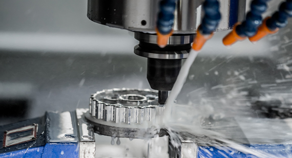
CNC machining drawing is a kind of engineering drawing that includes machining. The abbreviated drawing of engineering drawing is to express the projection surface of the object according to the projection method. According to the different projection methods, it can be divided into orthographic projection and oblique projection. The most common engineering drawings are one-dimensional projection, two-dimensional projection and axonometric projection (stereoscopic projection is also called three-dimensional projection). The specific information required to manufacture parts with processing drawing features that are different from other types of engineering drawings includes material, size, and weight information.
In addition, information related to the material handling or quality of CNC machined parts will be found in the comment section, while engineering drawings provide specific requirements on the machined parts, such as tolerances, surface finish and material, they usually do not provide specific method needs Used to create features.

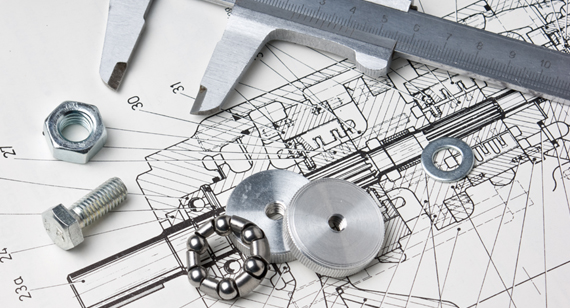
Engineering Drawing tools
Scale: The scale is used to draw lines of a specific length.
Drawing board: It is rectangular and made of wood about 25 mm thick. The back is fixed with 2 slats to prevent warping. The surface of the board should be flat and smooth for storing drawing paper. There is a working inch on the side of the drawing board.
Pencils: They are mainly used for drawing. The accuracy and appearance of the drawing depends on the quality of the pencil used. The grades of pencils are mainly H2H and HB.
Drawing paper: When choosing drawing paper, we must ensure that the size of the paper is smaller than the drawing board.
Pins, clips and tape: In order to destroy the paper, we use pins or clips or other preservation tape.
Set Square: The shape of a triangle, one of the corners is a right angle. Triangular plates generally have two forms, one is 45 degrees and 90 degrees, and the other is 30 degrees, 60 degrees, and 90 degrees. The triangular board is a combination of t-square, used to draw an angled line.
T-Square: T-square consists of two parts: stock and blade connected together at right angles by screws and pins. T-shaped grid is installed on the side of the drawing board, along the edge of the drawing board, used to draw horizontal straight lines.
Protractor: It is a flat semicircle, the circumference edge is divided into 1 degree, and it is numbered every 10 degrees, and the two ends are readable. The protractor is used to draw or measure angles.
Draftsman: The combination of a T-square, a set of square scales and a protractor is a draftsman. One end of it is clamped by a screw on the edge of the drawing board. The other end is adjustable, it has a 90-degree scale, and a protractor that can rotate a certain angle. This scale can be moved anywhere we want within its range.
Roller scale: There are rollers inside. Used to draw vertical lines, horizontal lines, parallel lines, angles and circles.
French curve: made into various shapes, used to draw curves that cannot be drawn with compasses, and used to draw ellipse, parabola, hyperbola and other curves.
Compass: The compass is used to draw a circle with a specific radius and an arc with a specific distance.
Eraser: Soft Indian rubber is widely used to erase pencil drawings, and the eraser should not damage the surface of the paper.
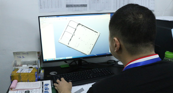
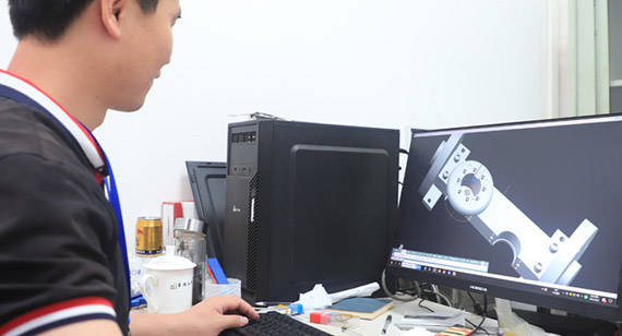
Computer drawing software:
1. AutoCAD software
AutoCAD (Autodesk Computer Aided Design) is a computer-aided design software designed by Autodesk Co., Ltd. of the United States. Mainly used for two-dimensional drawing and basic three-dimensional design. It is widely used in CNC machining industry, engineering drawing, mold industry, construction industry, etc.
2. Pro/Engineer (Pro/e) software
The Pro/Engineer (Pro/e) operating software is a CAD/CAM/CAE integrated three-dimensional software owned by Parametric Technology Corporation (PTC). Pro/E adopts a parametric design module method, which can perform sketch drawing, part production, assembly design, sheet metal design, processing, etc., and is widely used in automobiles, molds, medical equipment and other fields. Due to the parametric design, it is convenient to change, the design cycle time is short, and the design efficiency of the product is greatly improved.
3. Cimatron software
Cimatron is a product of Cimatron, a well-known software company in Israel. As a leader in CAD/CAM integrated solutions for manufacturing, it promises to provide molds, tools and other manufacturers with comprehensive, cost-effective software solutions, mainly in processing In manufacturing model processing and tool path editing, especially in CNC programming machining, it is widely used and powerful, ensuring that the product manufactured every time is the product you design.
4.solidworks software
SolidWorks is a subsidiary of Dassault Systemes S.A. It is responsible for R&D and sales of window products of mechanical design software. It is a 3D CAD design software with powerful design functions and an easy-to-learn and easy-to-use operation interface. The switching between part design, assembly design and engineering drawing is all related. It is widely used in machinery design, automobile design, mold development and other industries.
5. Rhino software
Rhino is a powerful advanced 3D modeling software based on NURBS launched by Robert McNeel of the United States in 1998. It is also what 3D experts call-rhino software. It is widely used in the life handicraft design industry. Unlike other three-dimensional software, it is only a few gigabytes in size. After installation, it is only 20 megabytes, and the configuration requirements for the installation computer are very low. Contains professional plug-ins for all walks of life, such as shoe plug-in RhinoShoe, ship plug-in Orca3D, dental plug-in DentalShaper for Rhino and so on.
6.UG software
UG (Unigraphics NX) is a product engineering solution software produced by Siemens PLM Software. It provides a practically proven solution for the user's virtual product design and process design requirements. It has powerful functions in three-dimensional design and product digital analysis. It provides graphics, three-dimensional modeling, processing and other modules, especially for CNC programming. It provides great help. It is widely used in mold processing programming, handicraft design, aerospace design and other fields.
7.Catia software
CATIA is the flagship product development solution of Dassault in France. It can help CNC machining manufacturers design their future products through modeling, and supports all industries from the pre-project phase, specific design, analysis, simulation, assembly to maintenance. Design Flow. The modules provided are appearance design, mechanical design, equipment and system engineering, management digital prototype, mechanical processing and so on. Widely used in: automotive, aerospace, shipbuilding and other industries.
Conclusion
In conclusion, numerical control engineering relies heavily on various drawing tools to design and manufacture precision CNC components and products. CAD and CAM software play a vital role in creating accurate models and converting them into machine-readable code. Additionally, physical measuring tools complement the digital solutions, ensuring the highest level of accuracy in the manufacturing process.

 +86 15099911516


 Read more