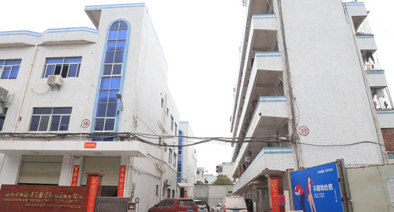
16 years one-stop China custom CNC machining parts factory

Hey there I’m VMT Sam!
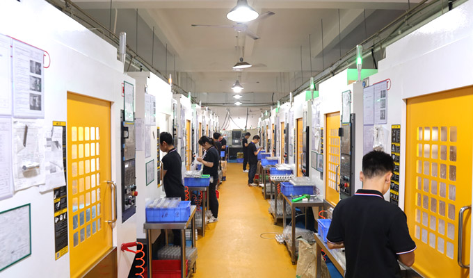
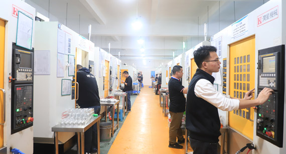
With 25 years of CNC machining experience we are committed to helping clients overcome 10000 complex part-processing challenges all to contribute to a better life through intelligent manufacturing. Contact us now
 514 |
Published by VMT at Sep 25 2021
514 |
Published by VMT at Sep 25 2021


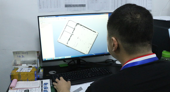
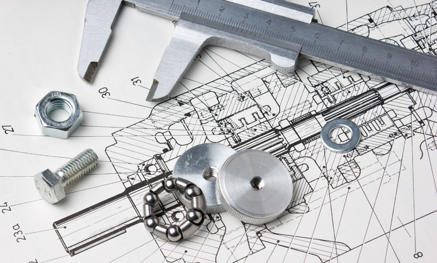
Nowadays CNC machining does not need to crawl on the workbench as before, and use drawing tools to describe the required machining details. On the eve of manufacturing, a computer is usually required to create CAD drawings and 3D models. After the drawings are completed, they are sent to the CNC machining manufacturer, who will quote according to the drawings. After the cooperation is established, it will give you relevant precautions and risk estimates based on DFM feedback. But if you don't make the drawings and give it to the partner, it will consume more time and personnel costs. Below we will lead you to understand how to prepare the drawings correctly.
The composition of CNC machining technical drawings
A standard technical drawing must include the title bar, coordinate information, views of the parts (orthogonal view, isometric view and cross-sectional view), detailed requirements and annotations.
Title bar: They are located at the bottom right of the drawing, and record the CNC machining part name, company and personnel information, process and material requirements, such as: CNC machining accuracy standards, material types, projection angles, part ratios, surface finish, etc.
Coordinate information
This is an information map that allows the position of CNC machined parts to be used as a reference point. It is usually used for large and complex technical drawings.
View of CNC machined parts
1. Orthogonal view: conveys the most important information about the geometry of CNC machining parts. These views contain most of the dimensions and tolerances.
2. Isometric drawing: Isometric view This is to make it easier for the mechanic to understand the shape of the CNC machined parts, which is usually presented in 3D drawings. In addition, it can also provide information such as installation direction and construction direction.
3. Sectional view: This is to make it easier to see the internal structure of the parts that cannot be seen clearly in other bitmaps, so as to better process the parts. It is characterized by their hatching pattern indicating the area where the material is cut. Complex CNC machined parts may have multiple section views.
Detailed requirements marking
When the orthographic view has areas that are complex and difficult to dimension, the detailed view is used to highlight these areas. The detailed view does not have to be the same size or placed on the same line as the orthographic view, and can be placed anywhere in the drawing. Detailed comments are marked with a letter to show which area of ??the orthogonal view is being detailed.
Labeling and annotation content
This usually appears in the lower left corner of the drawing to more conveniently prompt the CNC machining manufacturer's process description, surface finish, and parts assembly.
In the process of making drawings, active communication is required to avoid absolutely mandatory technology, which can save costs and best practices involving various standards. For example, the dimensions of the drawings have been marked in the CAD and 3D drawings, but you are afraid of missing you to save time by annotating only the key features that need to be measured by the mechanic.
How to prepare a good technical drawing of CNC machining parts?
First, draft a standard or non-standard technical drawing template, which can be based on the standard ASTM/DIN/ISO template, which can standardize detailed information such as specified coordinates, protection angles, and title bars. Non-standard, the template refers to a custom template, but this one needs to include all the necessary detailed information in the title bar.
The second step is to draw the view of the CNC machined parts, clearly mark the reserved size, complexity and precautions of the orthogonal view, isometric view, and cross-sectional view. It should be noted that the front view needs to be centered as much as possible.
The third step is to place construction lines such as center lines, center marks, and cut lines on all views.
How to add CNC machining part size?
To ensure that all dimension lines and graphics are clearly visible, and do not cross each other or the drawing. We provide you with the following points:
1. Add the overall size first, and then add other feature sizes.
2. Try to add all dimensions on the view from the common baseline.
3. When a feature is visible in multiple views, it is not necessary to mark its size on all views. Conversely, when multiple features are not visible on the view, the size of the feature should be described most clearly.
4. When there are multiple identical features, only add a size to one of them, indicating the number of times that feature appears in the current view. For example, if you can see three identical holes with a diameter of 2.1 mm on the plane orthogonal view of a CNC machined part, please add the following dimensions to one of the holes – 3 x 2.1.
Summarize
To make it easier for you to prepare drawings, we also have Design and engineering support (design and engineering support) service, if you can practice the drawings, we can provide DFM analysis services. This also allows us to execute your project more perfectly and deliver high-quality CNC machined parts. Now that you have learned how to prepare perfect technical drawings, please visit our quotation platform to upload your models and technical drawings to start your fast, stress-free and efficient manufacturing journey.

 +86 15099911516


 Read more