15 years one-stop China custom CNC machining parts factory

Hey there I’m VMT Sam!
With 25 years of CNC machining experience we are committed to helping clients overcome 10000 complex part-processing challenges all to contribute to a better life through intelligent manufacturing. Contact us now
 902 |
Published by VMT at Oct 13 2024
In CNC machining and precision engineering, achieving accurate and repeatable measurements is vital for producing high-quality parts. This is where GD&T (Geometric Dimensioning and Tolerancing) plays a critical role. A key component of GD&T is the concept of datums, which serve as reference points or features that guide the manufacturing, inspection, and assembly processes. Datums are essential in defining how a part should be positioned or aligned in relation to its surroundings or other parts.
This article will cover everything you need to know about datums, including their importance, different types, and how they are used in custom CNC machining to ensure precision and accuracy.
In GD&T, a datum is a theoretically perfect geometric reference point, line, or plane from which measurements are taken. These reference points establish a consistent frame of reference for defining the location, orientation, and form of features on a part. A datum feature, on the other hand, is the actual physical feature on the part that corresponds to the datum. For example, it could be a hole, a flat surface, or an axis.
Datums are critical in CNC machining services because they ensure that parts fit together as intended, especially when multiple components must align in an assembly. Without clearly defined datums, measurement errors and misalignment issues can occur, resulting in defective parts or products.

Understanding datums in GD&T is foundational for anyone involved in CNC prototype machining or large-scale production. Proper use of datums ensures that machining operations are carried out consistently and that parts meet their design specifications.
Datums and Datum Features
A datum feature is the actual part surface or feature that is used to establish the datum. For example, if a flat surface on a part is designated as a datum, it will serve as the reference point for all subsequent measurements and inspections.
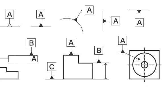
Datums are typically identified on engineering drawings using specific GD&T symbols (such as a rectangle with a capital letter inside, e.g., A, B, or C). These letters represent the order in which the datums are to be considered, starting from the primary datum, followed by the secondary and tertiary datums.

Datum Reference Frames
A Datum Reference Frame (DRF) is a coordinate system established using datums that define how a part is oriented or positioned during manufacturing and inspection. A DRF typically consists of three mutually perpendicular planes (representing X, Y, and Z axes) derived from the primary, secondary, and tertiary datums.
This reference frame forms the foundation for all dimensional controls in CNC machining parts and helps ensure that parts are produced to specification, especially in multi-axis operations.
Primary and Secondary Datums
Primary Datum: This is the most important reference point or surface from which other datums and features are measured. The primary datum typically represents the most critical or stable surface on the part.
Secondary Datum: The secondary datum is used to further refine the part’s position by providing another point of reference, usually perpendicular to the primary datum. It helps in establishing more accurate positional relationships for features that cannot be fully defined by the primary datum alone.
For example, in a cylindrical part, the primary datum may be the flat surface on one end, while the secondary datum could be the axis of the cylinder.
Datum targets are specific points, lines, or areas on a part that are used to establish the datum. These targets are often employed when the entire surface cannot be used as a datum, such as in complex or irregular shapes. Datum targets are crucial in CNC machining factories, where precise and repeatable measurements are needed for complex parts.
Datums and Datum Targets
While a datum generally represents an entire surface, datum targets pinpoint specific areas or features of that surface. These can be small, localized spots, lines, or even areas that are selected based on the design requirements.
For instance, when a surface is too irregular to serve as an entire datum, a datum target can be applied to three points on that surface to create a stable reference plane for machining or inspection.
How to Use Datum Targets?
Datum targets are typically used in parts where the surface is uneven, irregular, or partially inaccessible. For example, in custom CNC machining, a casting might have an irregular surface that can't serve as a full datum. Instead, datum targets are placed at strategic locations to ensure proper alignment during machining or inspection.
To use a datum target:
Identify the necessary points or areas on the part.
Place datum target symbols on the drawing, indicating the exact points to be referenced during machining or measurement.
Use the datum reference frame to establish alignment based on the selected datum targets.
Datum symbols are used on technical drawings to designate specific surfaces, axes, or features as datums. These symbols are standardized under GD&T and provide a clear visual representation of how parts should be measured and inspected in relation to one another.
Datum Symbols on Surfaces or Axes
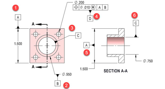
When a surface is used as a datum, the datum symbol is placed on the surface edge in the drawing. For an axis, the symbol is placed directly on the feature's centerline. This distinction is critical, especially in rotational parts like shafts or cylindrical components, where the axis often serves as the primary datum.
For example, in CNC prototype machining, when producing cylindrical parts, the axis of the part might serve as a key datum for ensuring alignment with other components.
Datum Symbols on Dimensional Features
Datum symbols can also be attached to dimensional features, such as holes or slots. In this case, the datum may not represent a surface but rather the geometric feature, which provides a critical reference point for further machining and measurement.
For example, a hole on a mounting plate may be defined as the primary datum, and the distance between this hole and other features will be measured relative to that datum to ensure precision in assembly.
In GD&T, datums are the foundation for defining how parts are measured, machined, and assembled. Without clear and well-defined datums, there is no way to ensure consistent results in CNC machining. Datums and datum features provide critical reference points that establish orientation and position, reducing errors and ensuring that parts meet their specifications.
Understanding how to use datums and datum reference frames is vital for achieving high precision in CNC machining services and delivering high-quality CNC machined parts.
Why are datums important in GD&T?
Datums are essential because they establish a consistent reference frame, allowing for accurate measurement, machining, and inspection. This ensures that parts are produced and assembled according to specification.
How do I select datums in GD&T?
Datums should be selected based on the most functionally important surfaces or features of the part. Choose surfaces that provide the most stability and are critical to the part’s performance or assembly.
Which GD&T symbols require datums?
Several GD&T symbols require datums, including position, profile, concentricity, parallelism, perpendicularity, and symmetry. These symbols are used to define geometric tolerances relative to one or more datums.
What is the purpose of datums?
The purpose of datums is to establish a reference frame that ensures consistency in manufacturing and inspection, guiding how parts are measured and aligned during assembly.
What are datums in drawings?
In drawings, datums are identified with symbols that indicate specific surfaces, axes, or features to serve as reference points for measurement and manufacturing processes.
Do all drawings require datums?
Not all drawings require datums, but for parts requiring high precision and assembly, datums are critical. They ensure that parts are produced within tolerance and will fit correctly in their final assembly.
How do I identify datums on drawings?
Datums are identified with capital letters (A, B, C, etc.) enclosed in a rectangle on the drawing. These letters correspond to the most critical surfaces, axes, or features for positioning and orientation.
Does flatness require datums?
Flatness does not require a datum because it controls the overall surface condition independently. However, flatness may be applied in conjunction with other geometric controls that do require datums.
Ready To Start Your Next Project?
Get Instant Quote

Request a Free Quote
Send us a message if you have any questions or request a quote. We will get back to you ASAP!
