15 years one-stop China custom CNC machining parts factory

Hey there I’m VMT Sam!
With 25 years of CNC machining experience we are committed to helping clients overcome 10000 complex part-processing challenges all to contribute to a better life through intelligent manufacturing. Contact us now
 832 |
Published by VMT at Aug 19 2024
In CNC machining part manufacturing, Geometric Dimensioning and Tolerancing (GD&T) is a crucial concept that ensures machining accuracy and the precise communication of design intent. Among the core elements of GD&T, flatness is a key parameter that measures the deviation of a part's surface from an ideal plane. This article aims to explore the definition, notation, and symbols of flatness in GD&T, as well as tolerance zones, application methods, and various measurement techniques. It also addresses common questions about flatness, helping CNC professionals better understand and apply this important concept.
Flatness in GD&T refers to the degree to which a part's surface is level compared to an ideal plane, specifically the maximum distance between any point on the surface and the ideal plane. It is used to describe the surface's machining error and is typically measured in millimeters or microns. Flatness is a critical aspect of ensuring a part’s stability and reliability in assembly, functionality, and performance.

In GD&T drawings, flatness is indicated by a specific symbol, usually a parallelogram, which may include numbers representing the tolerance range. For example, a notation of "FLATNESS 0.05" means that all points on the part’s surface must lie within a tolerance zone of ±0.025mm from the ideal plane. This notation does not require a reference plane or feature, directly reflecting the flatness requirements of the part’s surface.
The flatness tolerance zone is the region between two parallel planes that are offset from the ideal plane by a distance equal to the flatness tolerance. All points on the part’s surface must fall within this zone to meet the flatness requirement. Setting an appropriate tolerance zone helps control machining errors, ensuring the part’s stability and reliability in use.
Surface Flatness: In CNC machining, surface flatness directly impacts the assembly precision and functionality of the part. By setting a reasonable flatness tolerance, you can ensure that the part’s surface meets the necessary flatness to fulfill design requirements.
Derived Median Plane (DMP) Flatness: In some complex parts, controlling the relative positions of multiple planes is necessary. The concept of a Derived Median Plane (DMP) can be introduced, and flatness tolerance can be set for the DMP to indirectly control the flatness of related planes.
Local Flatness per Unit: For large surfaces requiring high flatness, a local flatness tolerance per unit length or area can be set. This approach helps control variations in flatness within smaller regions while ensuring overall flatness requirements are met.
Height Gauge: A height gauge is a simple and intuitive tool used to measure the distance from various points on a part’s surface to a reference plane. By taking multiple measurements and calculating the maximum difference, you can approximate the flatness of the part. However, this method is limited in accuracy and is susceptible to human error.
Surface Plate: A surface plate is a high-precision reference tool used for calibrating and measuring the flatness of parts. By placing the part on the surface plate and using precision measurement tools such as a height gauge or laser interferometer, more accurate flatness data can be obtained.
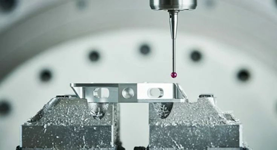
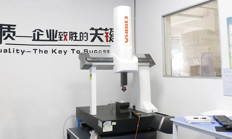
Coordinate Measuring Machine (CMM): CMMs are among the most widely used precision measurement tools in CNC machining. They use contact or non-contact sensors to measure multiple points on the part’s surface with high accuracy, and calculate the flatness of the part. CMMs offer high precision, efficiency, and automation, making them ideal for measuring the flatness of complex parts.

Flatness and straightness are both important parameters in GD&T used to describe shape errors, but they differ significantly in application and measurement methods. Straightness primarily focuses on the deviation of a part’s surface in a single direction, while flatness concerns the overall or local flatness of the entire surface. Straightness is typically measured by evaluating one or more linear tracks on the surface, whereas flatness requires consideration of the entire surface or local areas.
VMT is an advanced simulation and optimization tool that can accurately simulate and verify GD&T requirements during the early stages of CNC machining projects. Engineers can use VMT to simulate the manufacturing, assembly, and use processes of parts in a virtual environment, identifying and correcting potential design flaws and manufacturing errors. For flatness control, VMT can help optimize machining parameters, adjust tool paths, and improve machining accuracy, ensuring that parts meet flatness requirements during actual production.

Flatness in GD&T is a critical concept in CNC machining part manufacturing. Through proper notation, strict tolerance zone settings, and precise measurement methods, the flatness of part surfaces can be ensured to meet design requirements. In practice, the choice of measurement tools and methods should be based on the specific part and machining requirements to ensure accurate and reliable results. Additionally, leveraging advanced technologies like VMT for simulation and optimization can further enhance manufacturing accuracy and performance stability.
What is the best tool for measuring flatness?
The best tool for measuring flatness depends on the specific part and measurement requirements. For simple parts and preliminary evaluations, a height gauge may be a quick and economical option. However, for complex parts requiring high-precision measurements, a Coordinate Measuring Machine (CMM) is typically the best choice, offering precise contact or non-contact measurements and comprehensive surface data.
What standards apply to flatness in GD&T?
Flatness in GD&T follows standards set by the International Organization for Standardization (ISO) and the American Society of Mechanical Engineers (ASME), such as ASME Y14.5M-1994 (with updated versions) or ISO 1101. These standards provide detailed guidelines for GD&T symbols, tolerance zone definitions, notation methods, and measurement principles, offering engineers a unified framework for design and manufacturing.
Can flatness be used to evaluate tolerance stack-up?
While flatness itself is not directly used to evaluate tolerance stack-up, it is an important factor in tolerance stack-up analysis. In complex assemblies, the flatness tolerances of multiple parts may accumulate, affecting the overall assembly precision. Therefore, it is essential to consider the flatness tolerance of each part in tolerance stack-up analysis to ensure that the final assembly meets design requirements.
Does flatness require a reference?
In GD&T, flatness does not usually require a specific reference plane or feature, as it describes the deviation of a part’s surface from an ideal plane. However, in some cases, where flatness tolerance is related to other geometric features (such as parallelism or perpendicularity), a reference plane or feature may be needed to ensure measurement accuracy and consistency.
How is flatness error measured?
Flatness error can be measured using various methods depending on the part’s shape, size, and measurement requirements. Common methods include single-point or multi-point measurement with a height gauge, comparison measurement using a surface plate and precision tools, and full-surface scanning with a Coordinate Measuring Machine (CMM). Regardless of the method used, it is crucial to ensure the accuracy and precision of the measurement tools and to follow the appropriate measurement standards and procedures.
In summary, flatness in GD&T is an indispensable concept in CNC machining part manufacturing. By using proper notation, strict tolerance control, and precise measurement methods, the flatness of a part’s surface can be ensured to meet design requirements, ultimately improving product quality and performance. As technology continues to advance and manufacturing demands grow more complex, ongoing exploration and application of new measurement techniques and methods will be essential to meet increasingly stringent machining requirements.
Ready To Start Your Next Project?
Get Instant Quote

Request a Free Quote
Send us a message if you have any questions or request a quote. We will get back to you ASAP!
