15 years one-stop China custom CNC machining parts factory
 582 |
Published by VMT at Aug 08 2024
Threads play a crucial role in CNC machining for parts manufacturing, serving as essential elements for connection, transmission, and sealing. Understanding the types of threads and their geometric parameters is vital for ensuring machining precision, connection reliability, and performance. This article begins with the definition of threads and explores their geometric parameters, characteristics of different thread types, tools and methods for identifying threads, and essential tips for selecting the correct threads. Additionally, it addresses common questions about thread types and geometric parameters.
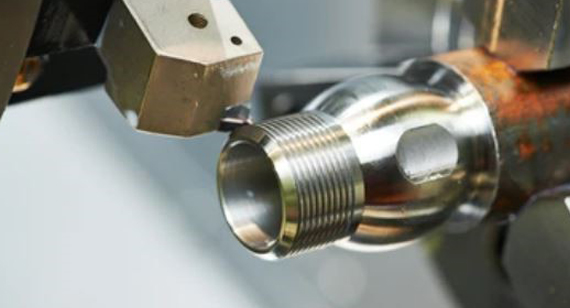
A thread is a helical structure with ridges and grooves created on the surface of cylindrical or conical parts. It functions to connect, transmit, or seal components through tightening or loosening operations. Threads are widely used in various fields, including machinery, automotive, aerospace, and medical devices.
Major Diameter (Thread Outer Diameter)
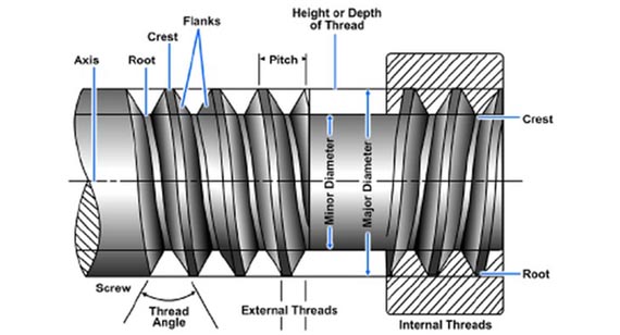
The major diameter (d or D) is the diameter at the crest of the thread, also known as the nominal diameter. It determines the maximum size of the thread and is one of the most critical dimensions in thread connections. Ensuring the precision of the major diameter is crucial for proper fitting between parts.
Minor Diameter (Thread Inner Diameter)
The minor diameter (d1 or D1) is the diameter at the root of the thread. The minor diameter directly affects the thread's strength and connection capability, often serving as the diameter for calculating the critical cross-section of the screw.
Pitch Diameter (Effective Diameter)
The pitch diameter (d2 or D2) is the imaginary diameter where the width of the groove and ridge are equal. It is approximately the mean diameter of the thread, determining the thread's geometric properties and fit, and is crucial for thread design and calculations.
Pitch
Pitch (P) is the distance between the crests or roots of adjacent threads. The pitch size determines the thread's tightness and engagement length. Precise control of pitch is essential for ensuring thread quality and performance in CNC machining.
Lead
Lead (S) is the distance a thread travels along its axis in one complete turn. For single-start threads, the lead equals the pitch; for multi-start threads, the lead equals the pitch multiplied by the number of starts. Lead size influences the transmission efficiency and engagement speed of the thread.
Flank Angle (Thread Angle)
The flank angle (α) is the angle between the sides of the thread. The flank angle affects the thread's engagement and sealing performance. Different thread types have different flank angles, such as the standard 60° angle for common threads.
Thread Helix Angle
The helix angle (φ) is the angle between the tangent to the helix and a plane perpendicular to the thread axis. The helix angle determines the thread's self-locking capability, indicating whether the thread will loosen under load.
Thread Start
The thread start is the portion where the thread begins, and its shape and size significantly impact the ease of screwing in and out. Ensuring the precision and surface quality of the thread start is crucial in CNC machining.
Helix Angle
The helix angle (β) is the angle between the helix and its axis, varying with the thread diameter. The helix angle size affects the transmission efficiency and self-locking capability of the thread.
Metric Threads (ISO Threads)
Metric threads are produced according to the International Organization for Standardization (ISO) standards and are widely used globally. Their dimensions and parameters follow ISO standards, ensuring interchangeability and universality.
British Standard Threads
1.British Standard Whitworth (BSW) Threads
BSW threads are coarse threads used for connections and fastenings, known for their larger pitch and better self-locking properties, typically used where high connection strength is required.
2.British Standard Fine (BSF) Threads
BSF threads have a smaller pitch and are used in applications requiring higher precision and sealing performance. Their longer engagement length provides better sealing.
3.British Association (BA) Threads
BA threads are small-diameter fine threads used in precision instruments and electronic devices, requiring selection based on specific application scenarios.
4.British Standard Pipe (BSP) Threads
BSP threads are used for pipe connections, including parallel pipe threads (G) and tapered pipe threads (RP, RC, etc.). These thread types offer different sealing properties and connection methods suitable for various pipeline systems and environments.
| BSP Thread Size | Outside Diameter mm / inch | TPI |
| 1/16 Inch BSP | 7.7 mm / 0.304″ | 28 |
| 1/8 Inch BSP | 9.7 mm / 0.383″ | 28 |
| 1/4 Inch BSP | 13.16 mm / 0.518″ | 19 |
| 3/8 Inch BSP | 16.66 mm / 0.656″ | 19 |
| 1/2 Inch BSP | 20.99 mm / 0.825″ | 14 |
| 5/8 Inch BSP | 22.99 mm / 0.902″ | 14 |
| 3/4 Inch BSP | 26.44 mm / 1.041″ | 14 |
| 7/8 Inch BSP | 30.20 mm / 1.189″ | 14 |
| 1 Inch BSP | 33.25 mm / 1.309″ | 11 |
| 1-1/4 Inch BSP | 41.91 mm / 1.650″ | 11 |
| 1-1/2 Inch BSP | 47.80 mm / 1.882″ | 11 |
| 2 Inch BSP | 59.61 mm / 2.347″ | 11 |
| 2-1/4 Inch BSP | 65.71 mm / 2.587″ | 11 |
| 2-1/2 Inch BSP | 75.18 mm / 2.96″ | 11 |
| 3 Inch BSP | 87.88 mm / 3.46″ | 11 |
| 4 Inch BSP | 113.03 mm / 4.45″ | 11 |
| 5 Inch BSP | 138.43 mm / 5.45″ | 11 |
| 6 Inch BSP | 163.83 mm / 6.45″ | 11 |
The UTS is developed by the American National Standards Institute (ANSI) and widely used in North America. It includes UNC (coarse), UNF (fine), and UNEF (extra fine) thread types.
Right-Handed and Left-Handed Threads
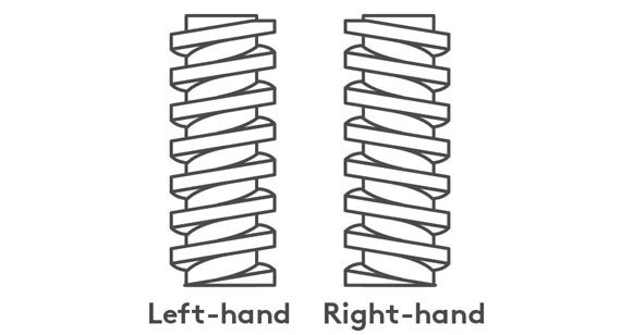
Right-handed threads rise from right to left and are the most common type used in mechanical connections. Conversely, left-handed threads rise from left to right, used in specific scenarios to prevent loosening.
Tapered Threads
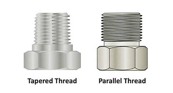
Tapered threads have diameters that gradually change from one end to the other, typically used for sealing or adjusting fitting tightness, like NPT (National Pipe Thread) widely used in piping systems.
V-Shaped Threads
V-shaped threads have a V-shaped profile, providing a larger contact area and better sealing performance, used in high-pressure, high-temperature, or corrosive environments.
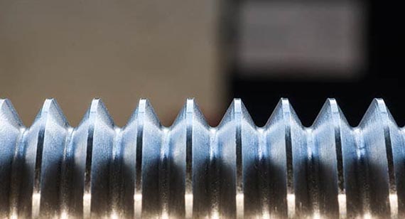
Square Threads
Square threads have rectangular or square profiles, offering high load-bearing and shear resistance, mainly used in heavy machinery connections.
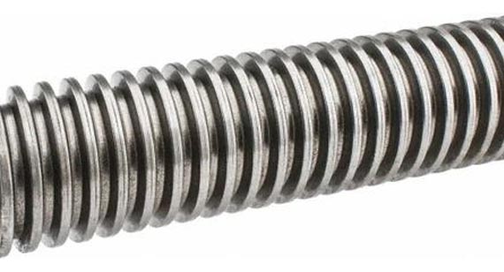
Joint Threads
Joint threads are specially designed for rotatable connections between two components, featuring larger helix angles and unique profiles for flexible and stable connections.
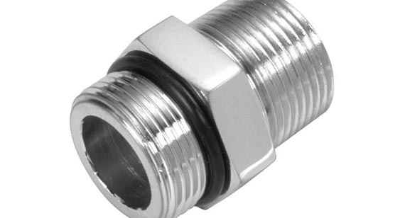
Trapezoidal Threads
Trapezoidal threads have a trapezoidal profile, providing excellent transmission performance and load-bearing capacity, commonly used in transmission devices like lead screws and worm gears.
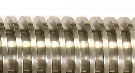
Round Threads
Round threads have rounded crests to reduce stress concentration and wear, typically used where frequent screwing in and out is required, such as bolt and nut connections.
Buttress Threads
Buttress threads have a saw-tooth profile, offering higher friction and self-locking performance, suitable for high-reliability and anti-loosening connections.
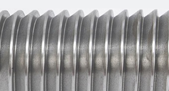
Worm Threads
Worm threads, or worm gears, are special types of helical threads used in transmission devices to achieve high transmission ratios and small axial force transfer.
Single and Multi-Start Threads
Single-start threads have one helical line, while multi-start threads have multiple helical lines, increasing transmission efficiency and load-bearing capacity, though more challenging and costly to manufacture.
Identifying thread types and geometric parameters requires professional measuring tools to help engineers and technicians quickly and accurately obtain relevant thread information.
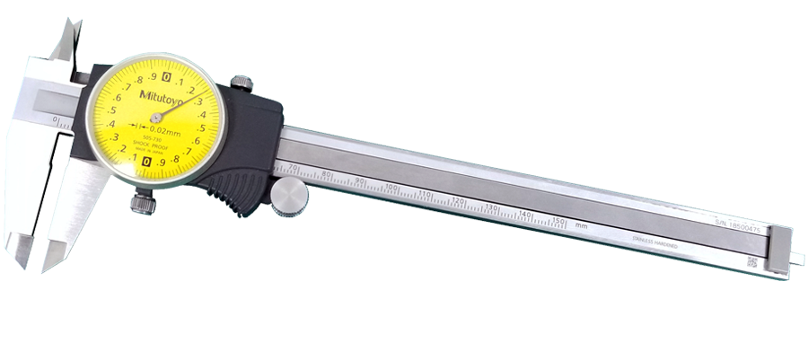
Calipers
Calipers measure the major diameter, minor diameter, and pitch of threads. By measuring the crest and root diameters, the major and minor diameters can be calculated, while the distance between adjacent crests or roots determines the pitch size.
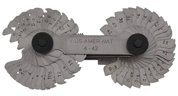
Thread Pitch Gauge
A thread pitch gauge is a tool specifically used to measure the pitch of threads. It typically includes a series of different pitch heads to match and measure the thread pitch accurately.
Identifying thread types involves considering geometric parameters, profile shapes, helix direction, and application scenarios. Below are step-by-step methods for identification.
Step 1 – External and Internal Threads
Determine if the thread is external or internal. External threads are found on bolts and screws, while internal threads are on nuts and pipe fittings.
Step 2 – Tapered and Parallel Threads
Identify whether the thread is tapered or parallel. Tapered threads have diameters that change, while parallel threads have constant diameters, determined by observing the thread shape and measuring diameters at different positions.
Step 3 – Determine Thread Pitch
Measure the thread pitch using a thread pitch gauge or calipers, as the pitch is a critical parameter for identifying thread types.
Step 4 – Measure Thread Dimensions
Measure the minor diameter, major diameter, and flank angle to determine specific thread types and standards.
Step 5 – Specify Thread Type Standard
Based on the measured parameters and thread characteristics, refer to relevant thread standards manuals or databases to identify the specific thread type and standard.
NPT/NPTF Thread Type – National Pipe Tapered (Fuel)
|
Dash Size (Nominal Size) |
Thread Pitch | Male Thread O.D. mm | Male Thread O.D. inches | Female Thread I.D. mm | Female Thread I.D. inches |
|---|---|---|---|---|---|
|
-02 (1/8) |
27 |
10.3 |
0.41 |
9.4 |
0.37 |
|
-04 (1/4) |
18 |
13.7 |
0.54 |
12.4 |
0.49 |
|
-06 (3/8) |
18 |
17.3 |
0.68 |
15.7 |
0.62 |
|
-08 (1/2) |
14 |
21.3 |
0.84 |
19.3 |
0.76 |
|
-10 (5/8) |
14 |
22.9 |
0.90 |
21.1 |
0.83 |
|
-12 (3/4) |
14 |
26.9 |
1.06 |
24.9 |
0.98 |
|
-16 (1) |
11½ |
33.3 |
1.31 |
31.5 |
1.24 |
|
-20 (1 ¼) |
11½ |
42.2 |
1.66 |
40.1 |
1.58 |
|
-24 (1 ½) |
11½ |
48.3 |
1.90 |
46.2 |
1.82 |
|
-32 (2) |
11½ |
60.4 |
2.38 |
57.9 |
2.29 |
*O.D. = Outside Diameter I.D. = Inside Diameter
G/BSP Thread Type – British Standard Pipe
|
Dash Size (Nominal Size) |
Thread Pitch | Male Thread O.D. mm | Male Thread O.D. inches | Female Thread I.D. mm | Female Thread I.D. inches |
| -02 (1/8) | 28 | 9.7 | 0.38 | 8.9 | 0.35 |
| -04 (1/4) | 19 | 13.2 | 0.52 | 11.9 | 0.47 |
| -06 (3/8) | 19 | 16.5 | 0.65 | 15.2 | 0.60 |
| -08 (1/2) | 14 | 20.8 | 0.82 | 19.1 | 0.75 |
| -10 (5/8) | 14 | 22.4 | 0.88 | 20.3 | 0.80 |
| -12 (3/4) | 14 | 26.4 | 1.04 | 24.6 | 0.97 |
| -16 (1) | 11 | 33.0 | 1.30 | 31.0 | 1.22 |
| -20 (1 ¼) | 11 | 41.9 | 1.65 | 39.6 | 1.56 |
| -24 (1 ½) | 11 | 47.8 | 1.88 | 45.5 | 1.79 |
| -32 (2) | 11 | 59.7 | 2.35 | 57.4 | 2.26 |
*O.D. = Outside Diameter I.D. = Inside Diameter
PT – JIS Tapered Pipe Thread Type
| Dash Size
(Nominal Size) |
Thread Pitch | Male Thread O.D. mm | Male Thread O.D. inches | Female Thread I.D. mm | Female Thread I.D. inches |
| -02 (1/8) | 28 | 9.4 | 0.37 | 8.1 | 0.32 |
| -04 (1/4) | 19 | 13.7 | 0.53 | 12.4 | 0.49 |
| -06 (3/8) | 19 | 17.2 | 0.68 | 16 | 0.62 |
| -08 (1/2) | 14 | 21.5 | 0.84 | 19.8 | 0.77 |
| -10 (5/8) | 14 | 23.1 | 0.91 | 20.6 | 0.81 |
| -12 (3/4) | 14 | 26.9 | 1.06 | 25.4 | 1 |
| -16 (1) | 11 | 34 | 1.34 | 31.8 | 1.25 |
| -20 (1 ¼) | 11 | 42.6 | 1.68 | 40.4 | 1.59 |
| -24 (1 ½) | 11 | 48.5 | 1.9 | 46.2 | 1.81 |
| -32 (2) | 11 | 60.4 | 2.37 | 58.2 | 2.29 |
*O.D. = Outside Diameter I.D. = Inside Diameter
SAE Thread Type – Straight Thread O-Ring Boss
| Dash Size
(Nominal Size) |
Thread Pitch | Male Thread O.D. mm | Male Thread O.D. inches | Female Thread I.D. mm | Female Thread I.D. inches |
| -02 (1/8) | 24 | 3.9 | 0.31 | 6.9 | 0.27 |
| -03 (3/16) | 24 | 9.6 | 0.38 | 8.6 | 0.34 |
| -04(1/4) | 20 | 11.2 | 0.44 | 9.9 | 0.39 |
| -05(5/16) | 20 | 12.7 | 0.5 | 11.4 | 0.45 |
| -06(3/8) | 18 | 14.2 | 0.56 | 12.9 | 0.51 |
| -08(1/2) | 16 | 19 | 0.75 | 17 | 0.67 |
| -10(5/8) | 14 | 22.3 | 0.88 | 20.3 | 0.8 |
| -12(3/4) | 12 | 26.9 | 1.06 | 24.9 | 0.98 |
| -14(7/8) | 12 | 30 | 1.18 | 27.7 | 1.09 |
| -16(1) | 12 | 33.3 | 1.31 | 31 | 1.22 |
| -20(1 ¼) | 12 | 41.4 | 1.63 | 39.1 | 1.54 |
| -24(1 ½) | 12 | 47.7 | 1.88 | 45.5 | 1.79 |
| -32(2) | 12 | 63.5 | 2.5 | 61.2 | 2.41 |
*O.D. = Outside Diameter I.D. = Inside Diameter
Metric Tapered/Parallel Thread Type
| SI Metric Port Size mm | Thread Pitch mm | Male Thread O.D. mm | Male Thread O.D. inches |
| M5 × 0,8 | .8 | 5 | 0.1968 |
| M8 × 1,0 | 1 | 8 | 0.3150 |
| M10 × 1,0 | 1 | 10 | 0.3937 |
| M12 × 1,5 | 1.5 | 12 | 0.4724 |
| M14 × 1,5 | 1.5 | 14 | 0.5512 |
| M16 × 1,5 | 1.5 | 16 | 0.6299 |
| M18 × 1,5 | 1.5 | 18 | 0.7087 |
| M22 × 1,5 | 1.5 | 22 | 0.8661 |
| M27 × 2,0 | 2 | 27 | 1.063 |
| M33 × 2,0 | 2 | 33 | 1.299 |
| M42 × 2,0 | 2 | 42 | 1.654 |
| M50 × 2,0 | 2 | 50 | 1.969 |
| M60 × 2,0 | 2 | 60 | 2.362 |
*O.D. = Outside Diameter
Understand Application Scenarios
Clarify the application scenarios and functional requirements, such as connection strength, sealing performance, and transmission efficiency.
Consider Material Characteristics
Different materials have varying mechanical and processing properties, so choose the appropriate thread type and parameters based on material characteristics.
Follow Standard Norms
Adhere to relevant international or national standards to ensure interchangeability and universality.
Consider Processing Costs
Different thread types have varying processing difficulties and costs, so consider cost factors while meeting functional requirements.
Conduct Trial Validation
Trial validation is crucial before finalizing thread types. Through actual assembly and testing for connection strength, sealing performance, and transmission efficiency, ensure the selected thread type meets design requirements and performs well. Trial validation also helps identify potential issues for adjustments and optimization before mass production.
Threads are essential elements in CNC machining parts manufacturing, with their type and geometric parameters significantly affecting part performance and lifespan. Understanding different thread types, mastering geometric parameter measurement methods, and using professional identification tools enable accurate identification and determination of thread types and parameters. When selecting threads, consider application scenarios, material characteristics, standard norms, and processing costs, and conduct trial validation for reliable thread selection. This approach ensures part quality and performance, leading to successful applications in various fields.
By mastering thread identification, geometric parameter measurement, and selection, professionals can achieve reliable and precise thread connections, ensuring parts' durability and functionality in diverse applications.
1. What are the three basic types of threads?
Threads can be broadly classified into three main types based on their application:
Connection Threads: These are used for fastening parts together, such as bolts and nuts.
Transmission Threads: These are designed for power and motion transfer, such as lead screws and worm gears.
Sealing Threads: These threads are used to achieve sealing functions to prevent leakage of fluids or gases.
2. What are the most common thread types?
Some of the most common thread types include:
Metric Threads: Such as M-series threads, which are based on the International System of Units (SI).
Unified Threads: Such as UNC (Unified National Coarse) and UNF (Unified National Fine), commonly used in the United States.
Pipe Threads: Such as NPT (National Pipe Thread) and BSP (British Standard Pipe), used for piping systems and fluid connections.
3. How are threads classified?
Threads can be classified in several ways:
By Direction: Right-hand threads and left-hand threads.
By Shape: Straight threads, tapered threads, and special profiles like trapezoidal or serrated threads.
By Purpose: Connection threads, transmission threads, and sealing threads.
By Standards: International standards (ISO), national standards (such as ANSI), and industry-specific standards.
4. What are NC and NF threads?
NC (Unified National Coarse) and NF (Unified National Fine) are types of threads defined by the Unified Thread Standard (UTS) in the United States.
NC Threads: Have a coarser pitch, making them suitable for general applications and easy assembly and disassembly.
NF Threads: Feature a finer pitch, providing higher precision and better sealing capabilities, ideal for applications requiring more precise connections.
5. When to use UNC and UNF threads?
UNC Threads (Unified National Coarse): Used for general-purpose applications where quick assembly and disassembly are needed. They have a larger pitch, which is suitable for faster production and less precision.
UNF Threads (Unified National Fine): Used where higher precision and tighter sealing are required. They have a smaller pitch, providing better strength and seal in applications that demand more accuracy.
6. What is ISO thread?
ISO threads refer to threads that conform to the standards set by the International Organization for Standardization (ISO). These threads are designed to be universally interchangeable and are widely used across various industries. ISO threads include:
Metric Threads: Measured in millimeters, following the ISO metric thread standards.
British Standard Threads: Also included in ISO standards for compatibility with international practices.
By adhering to ISO thread standards, you ensure that threaded components can be interconnected and used globally, facilitating consistency and reliability in manufacturing and assembly processes.
