16 years one-stop China custom CNC machining parts factory

Hey there I’m VMT Sam!
With 25 years of CNC machining experience we are committed to helping clients overcome 10000 complex part-processing challenges all to contribute to a better life through intelligent manufacturing. Contact us now
 266 |
Published by VMT at Oct 26 2022
266 |
Published by VMT at Oct 26 2022


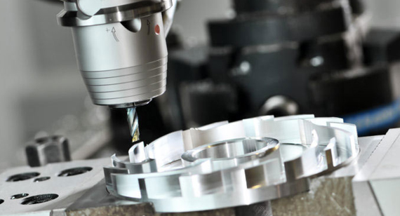
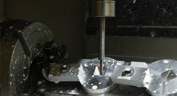
Milling cutters are generally multi-blade tools. Because of the many teeth and long cutting edges involved in cutting at the same time, and the ability to use higher cutting speeds, the productivity is high. Different milling cutters can be used to process planes, grooves, steps, etc., as well as the tooth profiles of gears, threads, spline shafts and various forming surfaces. The following is a brief analysis of the structure, types, uses of milling cutters and how to choose down milling or up milling by the VMT CNC machining factory.
The structure of the milling cutter
Take an indexable milling cutter as an example:
1. Main geometric angles
The milling cutter has a main declination angle and two rake angles, one is called the axial rake angle and the other is called the radial rake angle.
The radial rake angle γf and the axial rake angle γp, the radial rake angle γf mainly affects the cutting power; the axial rake angle γp affects the formation of chips and the direction of the axial force. When γp is a positive value, the chips fly away from the machining. noodle.
Rake angle (rake face contact surface)
Negative rake angle: generally used in cnc machining plants for steel, steel alloy, stainless steel, cast iron.
Positive rake angle: for viscous materials and some superalloys.
Front corner center: for threading, grooving, profiling and forming knives. Use negative rake angles whenever possible.
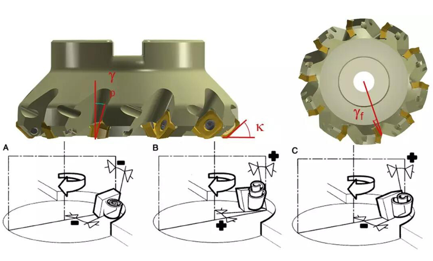
2. Geometry of milling cutter
The first is: positive angle - positive angle
The cutting is brisk, the chip evacuation is smooth but the cutting edge strength is poor. It is suitable for CNC machining soft materials and stainless steel, heat-resistant steel, ordinary steel and cast iron, etc. This form should be preferred for low-power machine tools, insufficient rigidity of the process system, and when there is built-up edge.
Advantage:
smooth cutting
Smooth chip evacuation
good surface roughness
Disadvantage:
Cutting edge strength.
Not conducive to cutting into contact.
The workpiece is released from the machine table.
Followed by: Negative Angle - Negative Angle
Strong impact resistance, with negative inserts, suitable for rough milling of cast steel, cast iron and high hardness, high strength steel.
However, CNC milling consumes a lot of power and requires excellent process system rigidity.
Advantage:
Cutting edge strength
productivity
Push the workpiece towards the machine table
Disadvantage:
greater cutting force
Chip blocking
Finally: positive angle - negative angle
The cutting edge of the precision CNC parts machining factory has strong impact resistance and sharp cutting edge. Suitable for machining steel, cast steel and cast iron. The effect is also better when CNC milling with large allowance.
Advantage:
Smooth chip evacuation
favorable cutting force
Wide range of applications
3. Pitch of milling cutter
1) Dense teeth: high-speed feed, large milling force, and small chip space.
2) Standard teeth: conventional feed rate, milling force and chip space.
3) Sparse teeth: low-speed feed, small milling force, and large chip space.
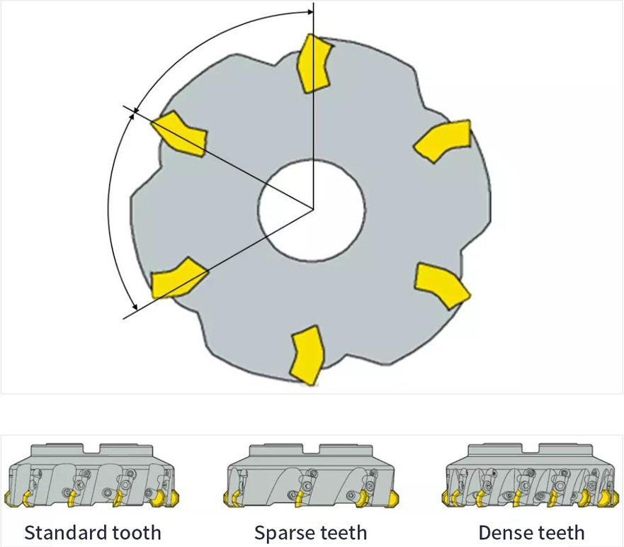
If the milling cutter is not fitted with a dedicated wiper insert, the surface finish depends on whether the feed per revolution exceeds the width of the insert wiper plane.
Number of teeth:
Coarse or standard teeth for slot milling (safety)
Close pitch for contour milling (productivity)
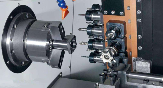
Types and uses of factory milling cutters for precision CNC machining parts
The types of milling cutters can be divided into sharp tooth milling cutters and spade tooth milling cutters according to the tooth structure. According to the relative position of the cutter teeth and the axis of the milling cutter, it can be divided into cylindrical milling cutters, angle milling cutters, face milling cutters, forming milling cutters, etc. According to the shape of the cutter teeth, it can be divided into straight tooth milling cutter, helical tooth milling cutter, angular tooth milling cutter and curved tooth milling cutter. According to the tool structure, it can be divided into integral milling cutter, combined milling cutter, group or complete milling cutter, insert milling cutter, machine clamp welding milling cutter, indexable milling cutter, etc. But it is usually divided in the form of CNC machining of the back of the cutting tool.
Sharp tooth milling cutters can be divided into the following categories:
(1) Face milling cutters There are integral face milling cutters, insert face milling cutters, machine-clamped indexable face milling cutters, etc., which are used for roughing, semi-finishing and finishing of various planes and stepped surfaces.
(2) End mills are used for CNC milling of stepped surfaces, side surfaces, groove recesses, holes of various shapes on parts, and inner and outer curved surfaces. If the end mills are easily distinguished, they can be divided into two categories: left-handed and right-handed. Many people still have no concept of left-handed and right-handed.
Right hand milling cutter:
First, determine whether the tool is left-handed or right-handed according to the following methods. In the face of a vertically placed milling cutter, if the blade groove rises from the lower left to the upper right, it is a right-hand rotation; if the blade groove rises from the lower right to the upper left, this is a left-hand rotation. The right-hand rule can also be used for right-hand rotation. The four curved fingers are the direction of rotation, and the raised thumb is the direction of right-hand rotation. The helical flute is used for chip containment, and it is also the part that constitutes the rake angle and front of the milling cutter.
Left hand milling cutter:
Left-handed milling cutters are generally selected for high-precision CNC machining. Left-handed milling cutters are generally used in the CNC machining of mobile phone buttons, membrane switch panels, LCD panels, acrylic lenses and other finishing. Precision CNC machining parts factory, but there are some high requirements, especially some mobile phone buttons or electrical panel production and CNC machining, high precision and high finish requirements are also high, we must choose the lower row of cutting, turn left, so as to avoid The phenomenon of whitening of the knife edge and the edge of the CNC machined part's incision are avoided.
(3) Keyway milling cutter: used for milling keyway, etc.
(4) Slot milling cutter and saw blade milling cutter: used for milling various slots, sides, stepped surfaces and sawing.
(5) Special slot milling cutter: It is used for milling various special groove shapes, such as shaped slot milling cutter, half-moon key slot milling cutter, dovetail slot milling cutter, etc.
(6) Angle milling cutter: used for straight grooves, spiral grooves, etc. of milling tools.
(7) Mold milling cutter: used for milling the convex and concave forming surfaces of various molds.
(8) Group milling cutter: combine several milling cutters into a set of milling cutters, which are used for CNC milling of complex forming surfaces, surfaces and wide planes of different parts of large parts.
Spade tooth milling cutters: Some milling cutters that require the front face to remain in the original truncation shape, and their back teeth are in the form of spade teeth, including disc slot milling cutters, convex semicircular cutters, concave semicircular cutters, double-angle cutters, forming cutters knife etc.
Down milling and up milling in CNC machining factory
There are two ways relative to the feed direction of the workpiece and the rotation direction of the milling cutter:
The first is down milling. The rotation direction of the milling cutter is the same as the feed direction of the cutting. At the beginning of the cutting, the milling cutter bites the workpiece and cuts off the last chip.
The second is up-cut milling. The rotation direction of the milling cutter is opposite to the feeding direction of the cutting. The milling cutter must slip on the workpiece for a period before starting to cut, starting with the cutting thickness of zero, and reaching the cutting thickness at the end of the cutting. maximum.
The cutting force has different directions in the face milling cutter, some end milling or face milling. When face milling, the milling cutter is just outside the workpiece, and the direction of the cutting force should be paid special attention. During climb milling, the cutting force presses the workpiece toward the table, while in up milling, the cutting force makes the workpiece leave the table.
Since the cutting effect of down milling is the best, down milling is usually the first choice. Only when there is a thread clearance problem on the machine tool or a problem that cannot be solved by down milling, up milling is considered. Ideally, the diameter of the milling cutter should be larger than the width of the workpiece, and the axis of the milling cutter should always be slightly away from the centerline of the workpiece. When the tool is placed directly on the cutting center, it is very easy to produce burrs.
The direction of the radial cutting force will change continuously as the cutting edge enters and exits the cut, the machine tool spindle may vibrate and be damaged, the insert may chip and the machined surface will be very rough, the milling cutter will be slightly off center, and the cutting force direction will no longer fluctuate - The milling cutter will receive a preload. We can compare center milling to driving in the center of the road.
Every time a milling cutter insert enters a cut, the cutting edge is subjected to an impact load that depends on the cross section of the chip, the workpiece material and the type of cut. When cutting in and out, the correct engagement between the cutting edge and the workpiece is an important direction.
When the axis of the milling cutter is completely outside the width of the workpiece, the impact force during cutting is borne by the outermost tip of the insert, which means that the initial impact load is borne by the most sensitive part of the tool. The milling cutter also leaves the workpiece with the tip, that is to say, from the beginning of cutting to the departure, the cutting force acts on the outermost tip until the impact force is unloaded.
When the centerline of the milling cutter is exactly on the edge line of the workpiece, the insert is released from the cutting when the chip thickness reaches the maximum, and the impact load reaches the maximum when cutting in and out. When the axis of the milling cutter is within the width of the workpiece, the initial impact load during cutting is carried by the part farther from the most sensitive tip along the cutting edge, and the blade exits the cutting relatively smoothly when the tool is retracted.
For each insert, the way the cutting edge leaves the part when it is about to exit the cut is important. Remaining material near retraction may reduce blade clearance somewhat. As the chips break away from the workpiece, a momentary tensile force is created along the rake face of the insert and often produces burrs on the workpiece. This tensile force compromises the safety of the chip edge in dangerous situations.
Down milling and up milling comparison table
| Down milling and up milling comparison table | ||
|---|---|---|
| project | Down milling | Up milling |
| Cutting thickness | From big to small | From small to large |
| Rowing phenomenon | none | Have |
| Tool wear | slow | quick |
| Workpiece surface chill phenomenon | none | Have |
| Effect on workpiece | squeeze | lift up |
| Eliminate lead screw and nut clearance | none | Have |
| Vibration | Big | Small |
| Lost energy | Small | 5% to 15% larger |
| Surface roughness | it is good | Difference |
| Applications | finishing | roughing |

The above is just a summary of the VMT CNC machining factory. If you want to know more about CNC machining, you can contact us: inquiry@vimetal.com.cn to negotiate with us.

 +86 15099911516


 Read more