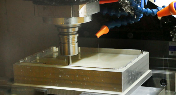
16 years one-stop China custom CNC machining parts factory

Hey there I’m VMT Sam!
With 25 years of CNC machining experience we are committed to helping clients overcome 10000 complex part-processing challenges all to contribute to a better life through intelligent manufacturing. Contact us now
 423 |
Published by VMT at Sep 23 2026 | Reading Time:About 6 minutes
423 |
Published by VMT at Sep 23 2026 | Reading Time:About 6 minutes


Rapid CNC machining starts with speed, delivering custom prototype parts in as little as one week. Beyond turnaround time, advances in modern CNC technology have made the process both highly cost-effective and remarkably precise (achieving tolerances down to ±0.01 mm). For instance, 5-axis CNC machining operates faster than traditional 3-axis setups while driving down the cost of complex geometries.
For issues like tight project deadlines, such as facing an upcoming EVT or PVT (verification test), only to hear from your supplier that production is queued until next month, Rapid CNC machining can save your timeline by leveraging automated scheduling and state-of-the-art multi-axis equipment. Furthermore, while common rapid techniques like 3D printing excel for visual concept models, they often fail under mechanical stress (e.g., snapping along layer lines during torque testing). When functional performance matters, turning to rapid CNC machining is the necessary next step.

This article provides a complete breakdown of rapid CNC machining, covering its definition, applications, core benefits, cost calculation and reduction strategies, comparison with other methods, and actionable DFM (Design for Manufacturability) guidelines. Finally, we share a case study detailing how we helped an industrial automation client optimize their CAD design to reduce machining costs by 22%, produce high-precision aluminum robotic arm parts via rapid CNC, and successfully pass 200+ hours of continuous fatigue testing.
Rapid CNC machining is far more than just cranked-up spindle speeds or high-RPM cutting tool paths. At its core, it is an integrated agile manufacturing model powered by digital intelligent scheduling, automated Design for Manufacturability (DFM) analysis, standardized modular fixturing systems, and high-precision multi-axis CNC machinery.
Unlike traditional machine shops where quoting, manual CAM programming, custom fixture building, and static scheduling can consume weeks, a digitized CNC workflow closes the administrative and technical gaps between 3D CAD files and physical parts. By leveraging real-time dynamic capacity allocation and automated DFM engines, setup times are drastically reduced.
For example: upload your STEP file on Monday at 9:00 AM, receive automated DFM feedback and a firm quote within 24 hours via intelligent cost-estimation algorithms, and have a complex 5-axis machined aluminum bracket finished, inspected, and shipped by Thursday afternoon.
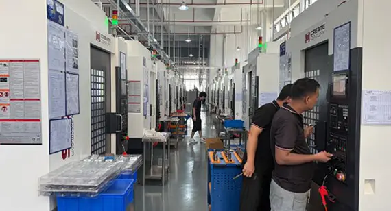
The 7-Step Agile Manufacturing Process for Rapid CNC Parts
To achieve rapid turnarounds without compromising geometric precision (achieving tolerances down to ±0.01 mm), the end-to-end manufacturing process relies on an optimal digital thread integrating Computer-Aided Design (CAD), Computer-Aided Manufacturing (CAM), and intelligent numerical control systems:
1. CAD Design and Digital File Transfer
The process begins in the engineer's 3D CAD software (e.g., SolidWorks, Fusion 360, STEP or IGES formats). Beyond geometric modeling, design engineers define essential tolerance callouts, surface roughness requirements (Ra), thread specifications, and material selections on 2D engineering drawings (PDF).
2. Automated DFM Analysis and Instant Quoting
Upon receiving the 3D CAD model, automated manufacturability engines analyze feature geometry (identifying undercuts, thin walls, deep pockets, and tight internal corner radii). Experienced engineers review potential machining bottlenecks and provide actionable DFM feedback within hours to prevent tool breakage, optimize tool paths, and lower production costs.
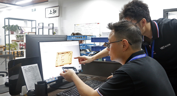
3. CAM Programming, Simulation, and G-Code Generation
Once the design is locked, engineers in CNC machining factory will translate the 3D model into precise cutter movement commands (G-code for motion control and M-code for auxiliary machine functions). Virtual toolpath simulations are conducted to verify cutting speeds, feed rates, step-overs, and tool clearances, ensuring zero collision risks and maximum cycle efficiency.
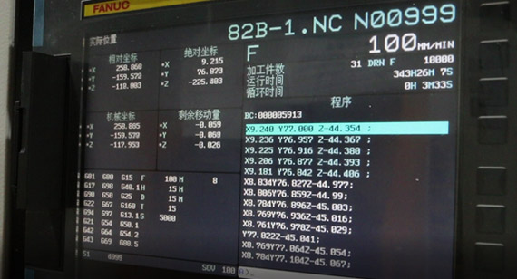
4. Digital Intelligent Scheduling and Quick-Change Fixturing
Unlike traditional manual queue management, an intelligent scheduling system dynamically assigns jobs to available CNC machine nodes based on workload, tool availability, and target delivery dates. Pre-inventoried billet stocks (AL 6061/7075, Stainless Steel, PEEK, POM) are paired with standardized modular quick-change fixturing systems (such as zero-point clamping), eliminating the time-consuming need for custom fixture fabrication.
5. High-Speed Multi-Axis CNC Machining
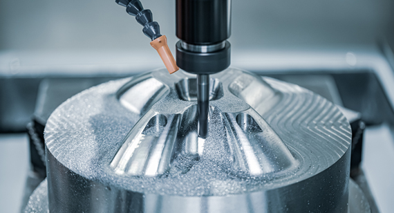
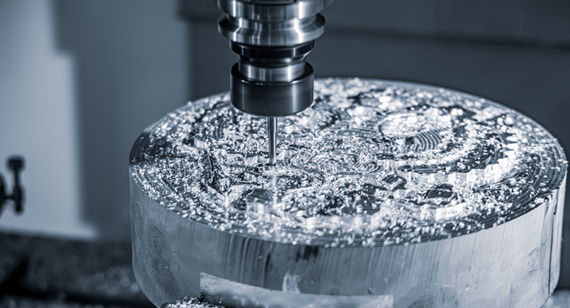
The G-code program is loaded directly into the CNC machine controller via a networked MES (Manufacturing Execution System). Closed-loop servo systems and high-speed spindles drive cutting tools along multi-axis trajectories (3-axis, 4-axis, or 5-axis indexing which depends on the machine types). Real-time monitoring sensors dynamically adjust operating parameters to maintain tight tolerances and superior surface finishes.
6. Surface Finishing and Post-Processing (Optional)
Depending on functional and cosmetic requirements, machined components undergo post-machining operations such as deburring, or surface treatments including bead blasting, Type II or Type III hardcoat anodizing, passivation, powder coating, or laser engraving.
7. Precision CMM Inspection and Express Delivery
Every finished part undergoes rigorous quality assurance. Critical dimensions are verified using Coordinate Measuring Machines (CMM), optical comparators, or pin gauges to guarantee compliance with engineering specs. Upon sign-off with a CMM inspection report, parts are dispatched via express air freight.
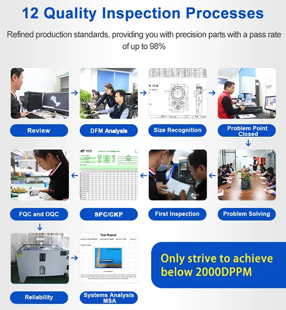
Rapid CNC machining combines high-precision numerical control technology with automated manufacturing systems to convert digital 3D CAD models into high-performance metal and plastic components. By modernizing traditional machining workflows, this technology provides product designers and hardware engineers with exceptional precision, production speed, and manufacturing adaptability throughout the product development lifecycle.
1. High Precision and Micron-Level Tolerances
Driven by advanced computer algorithms and closed-loop servo control systems, the machining process minimizes human error and thermal distortion. Standard machining tolerances reach ±0.01 mm to ±0.05 mm, with critical feature tolerances achieving micron-level precision (down to ±0.005 mm). This ensures exact geometric accuracy for demanding mechanical assemblies, bearing fits, and fluidic seals.
2. High Efficiency and Reduced Lead Times
Compared to conventional manual machining methods, Rapid CNC machining significantly increases material removal rates and cuts overall cycle times. By combining high-speed spindles with optimized cutter toolpaths, complex parts that once required weeks of manual setup can now be machined and finished within hours.
3. Excellent Material and Geometric Adaptability
The process offers high versatility across diverse engineering materials, shapes, and dimensional requirements. Whether manufacturing lightweight aluminum brackets, tough stainless steel housings, or temperature-resistant engineering plastics, CNC equipment adapts smoothly to varied project demands. Common materials include :
4. High Automation and Reduced Skill Dependency
The end-to-end machining execution is heavily automated by Computer-Aided Manufacturing (CAM) software and CNC controllers. Automated tool changers (ATC), tool setting probes, and standardized cutting parameters reduce reliance on manual operator skill levels while boosting part-to-part consistency.
5. Exceptional Program and Toolpath Flexibility
Unlike fixed manufacturing methods that require permanent tooling modifications, CNC machining relies on programmable G-code and M-code instructions. For changes like modify a hole location, adjust a wall thickness, or change tool selection, CAM programmers can rapidly update the digital code to alter toolpaths, allowing instantaneous engineering design changes.
6. Flexible Production and Dynamic Scheduling
By avoiding the need for expensive hard tooling and reducing custom fixtures, production lines and schedules can be adjusted dynamically. Additionally, rapid CNC machining allows you switch between processing single-unit prototypes and running low-volume production batches to accommodate shifting market demands and tight engineering validation timelines.
Rapid CNC machining technology is widely utilized across high-demand manufacturing sectors. Its combination of high precision, superior efficiency, and advanced automation enables engineering teams to rapidly transition from CAD concepts to functional testing.
Below are the primary industry applications along with the typical components produced via Rapid CNC machining:
Mechanical Manufacturing: Used for machining custom equipment parts and tooling. Typical components include high-load structural brackets, robot arm joints, hydraulic manifold blocks, pneumatic valve bodies, motor mounting plates, custom stepped shafts, and precision mold bases.
Electronics Manufacturing: Used for producing custom electronic packaging and thermal management parts. Typical components include custom aluminum device enclosures, waterproof sensor housings, high-efficiency LED heat sinks, liquid cooling cold plates, EMI shielding boxes, and precision connector hardware.
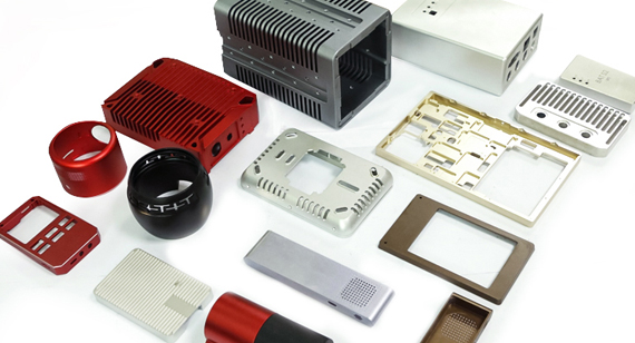
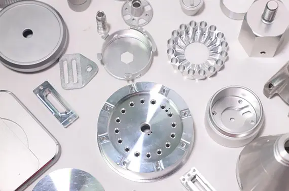
Aerospace: Used for machining high-strength, flight-critical components requiring strict tolerance controls and certified structural alloys. Typical components include drone chassis arms, lightweight structural frames, titanium engine brackets, fuel system manifolds, and high-precision sensor mounts.
Medical Devices: Used for manufacturing specialized medical instruments, biocompatible implants, and diagnostic tools. Typical components include surgical tool housings, titanium bone plate prototypes, diagnostic equipment chassis, liquid handling manifolds, and custom peristaltic pump components.
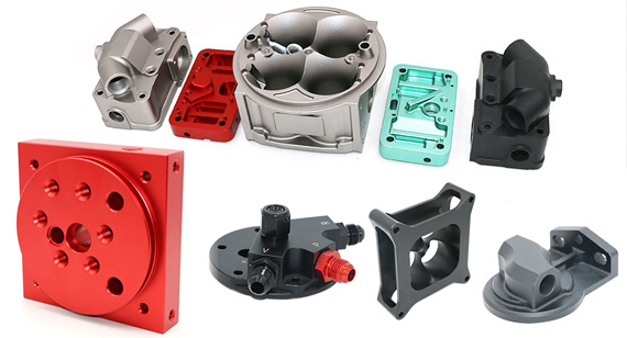
Automotive Manufacturing: Used for validating engine, chassis, and interior systems, custom intake manifolds, transmission shift levers, suspension arm prototypes.
Although we previously emphasized that Rapid machining relies heavily on intelligent scheduling, digital program modifications, and rapid DFM feedback, the continuous advancement of modern machine tool technology plays an equally vital role. Upgraded equipment capabilities drive production speed while optimizing manufacturing costs. Modern CNC machinery accelerates prototype lead times through the following improved technology:
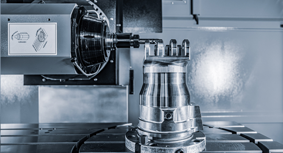
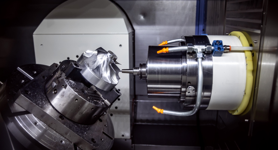
5-Axis CNC Machining Centers (or even 7\9\12 axis machines): Unlike traditional 3-axis machines that require multiple manual fixture re-orientations and custom jaw setups for multi-sided geometries, 5-axis machines approach workpieces from five axes simultaneously. Completing complex parts in a single setup cancel repeat manual alignments, cutting total turnaround times by up to 70% compared to conventional multi-step 3-axis setups.
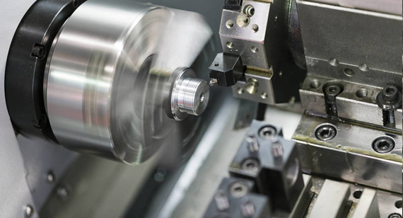
Turn-Mill Multi-Tasking Machines: Combining CNC turning, milling, cross-drilling, and tapping within a single workstation allows complex rotational parts (such as precision shafts with keyways or cross-holes) to be fully machined in one continuous process, saving intermediate transport and queue times between different machines.
High-Speed Spindles and Automated Tool Changers: Featuring high-RPM spindles and rapid automatic tool magazine swaps, modern machining centers perform aggressive material removal and fine surface finishing with minimal tool-change delays.
In-Machine Optical Probes and Automated Inspection: Automated workpiece alignment systems and tool setter probes calibrate part origin and tool length within seconds inside the machine enclosure, drastically reducing initial setup time before cutting begins.

Understanding rapid machining costs calculation allows your teams to budget accurately and identify clear opportunities for cost reduction. Rapid CNC machining costs are primarily driven by four core components:
Total Project Cost = Material Cost + Machining Time Cost + Setup and Tooling Cost + Post-Processing Cost
Examples of Rapid CNC Machining Cost Levels
Below is an estimated cost comparison for common custom CNC prototype parts in quantities of 1 to 5 units, including standard surface finishing and inspection:
| The Part | Typical Material | Dimensions | Relative Cost Level | Primary Cost Drivers |
| Simple Sensor Housing | AL 6061-T6 | 50 x 50 x 30 mm | US$ | Simple structure, short machining time, standard metal materials, low unit cost. |
| Complex Mounting Bracket | AL 7075-T6 | 120 x 80 x 40 mm | US$US$US$US$ | Medium complexity, involving multi-axis machining or tight assembly tolerances. |
| Precision Stepped Shaft | Stainless Steel 304 | OD 30 x L 150 mm | Medium complexity, involving multi-axis machining or tight assembly tolerances. | |
| Heat Sink / Cold Plate | AL 6061-T6 | 200 x 150 x 20 mm | US$US$US$ | Dense features (such as high-density heat fins) or long toolpaths, requiring extensive cutting time. |
| High-Temp Valve Body | PEEK Plastic | 80 x 60 x 50 mm | US$US$US$US$ | High-cost engineering plastics (such as PEEK) or specialty aerospace alloys, with high machining difficulty and expensive raw material cost. |
How to Optimize Rapid CNC Machining Costs?
While Rapid CNC machining delivers rapid turnaround times, minor design adjustments can yield substantial cost savings without sacrificing functional performance. Applied early in the design stage, the following DFM strategies can reduce machining expenses by 10% to 30%:
1. Standardize Internal Corner Radii
Avoid sharp internal 90-degree vertical corners or extremely small radii (for example, Radius less than 1.5 mm). Sharp corners require tiny end mills that cut at lower feed rates and are prone to breakage. Radii should be designed to match standard tool dimensions, ideally using an internal corner radius 1.5 to 2 times larger than standard tool radii to allow high-speed corner milling.
2. Avoid Deep and Narrow Pockets
Deep cavities with depth-to-width ratios exceeding 4:1 significantly increase tool deflection and vibration during machining. This forces operators to reduce cutting speeds and take multiple shallow passes. Keeping pockets shallow and wide drastically cuts machining time.
3. Limit Unnecessary Tight Tolerances
Specifying tight tolerances (such as +/- 0.005 mm) across non-critical surfaces forces additional CMM inspection checks, slower finishing passes, and increased machine wear. Reserve tight tolerances exclusively for critical features such as bearing fits, seal grooves, and precision locating holes, while applying standard tolerances (such as +/- 0.1 mm) elsewhere.
4. Design Parts for Single-Setup Machining
Repositioning a part across multiple axes requires custom clamping fixtures or manual operator re-alignment. Designing parts so that features can be machined from a single orientation, or utilizing 5-axis indexing, reduces non-cutting setup fees.
Design for Manufacturability (DFM) can promote the theoretical 3D CAD model into cost-effective, high-precision physical parts. Following these engineering rules ensures your design moves smoothly and effectively:
Wall Thickness Rules: Maintain minimum wall thicknesses to prevent part distortion and vibration under cutting forces.
Threaded Hole Specifications: Avoid tapping threads to the absolute bottom of a blind hole. Allow an unthreaded relief depth of at least 1.5 times the thread pitch at the bottom of blind holes. Limit thread engagement length to 2 to 3 times the nominal thread diameter, as longer threads offer negligible additional clamping strength while dramatically increasing tap breakage risk.
Standardize Feature Dimensions: Use standard metric hole diameters, thread sizes, and chamfer angles. Custom feature sizes require non-standard cutting tools, adding lead time and tooling costs.
Avoid Thin, Tall Ribs and Unsupported Features: Tall, thin structural elements lack rigidity during high-speed cutting. If tall features are necessary, incorporate a minimum draft angle or taper at the base to increase structural stiffness during milling.
While Rapid precision machining is the optimal choice for high-precision, structural, and production-grade functional components, understanding and comparing alternative rapid manufacturing processes will help you make a more informed technical decision. To support your process selection, the following table compares primary rapid manufacturing technologies across key engineering metrics:
| Criteria | Rapid CNC Machining | 3D Printing (SLA / SLS / DMLS) | Vacuum Casting (Urethane) | Rapid Injection Molding |
| Dimensional Tolerance | Highest: +/- 0.005 to 0.01 mm; Standard: +/- 0.02 to 0.05 mm | Moderate: +/- 0.1 mm to +/- 0.3 mm | Moderate: +/- 0.2 mm or 0.5% | High: +/- 0.05 mm to +/- 0.1 mm |
| Surface Finish (Ra) | Ra 0.8 - 3.2 µm (Up to Ra 0.4 µm with polishing) | Ra 3.2 - 12.5 µm (Stepping lines visible) | Ra 1.6 - 3.2 µm (Matches silicone master pattern) | Ra 0.8 - 3.2 µm (SPI mold finish standards) |
| Material Selection | Extensive: Any millable metal alloy, engineering plastic, or composite | Restricted: Specific photosensitive resins, polymer powders, or sinterable metal powders | Limited: Polyurethane resins simulating ABS, PP, PC, or Rubber | Broad: Production-grade thermoplastic resins |
| Mechanical Strength and Isotropy | 100% Isotropic: Full parent-material tensile strength and grain structure | Anisotropic / Variable: Weak z-axis layer bonding (varies by tech) | Moderate: Simulates plastics, prone to aging and micro-bubbles | 100% Isotropic: Full molded resin properties |
| Batch Cost | Cost-Effective (US$US$) for 10 to 1000 structural functional parts | Lowest (US$) for 1 to 10 non-load-bearing visual geometries | Cost-Effective (US$US$) for 10 to 50 pcs; ideal bridge before hard tooling US$US$ | High tooling fee (US$US$), highly economical for 1,000 to 10,000pcs |
| Lead Time Speed | Fast: 1 to 3 business days | Fastest: 1 to 2 business days | Moderate: 3 to 7 business days | Longest: 7 to 15 business days |
You can tell that for project demands certified production metals or engineering plastics, tight tolerances under +/- 0.01 mm, and 100% isotropic mechanical strength for load-bearing dynamic testing, Rapid CNC machining remains the definitive choice. For other development stages, alternative methods offer unique advantages. Additive manufacturing excels at producing complex, low-stress visual models where geometric freedom matters more than tight tolerances.
Meanwhile, for plastic parts, vacuum casting serves as an economical bridge for small batches of 10 to 50 plastic enclosures with custom textures, and rapid injection molding becomes ideal when transitioning to mid-volume production runs of up to 10,000 parts.
Optimize CAD design to reduce machining costs by 22%, produce high-precision aluminum robotic arm parts via rapid CNC, and successfully pass 200+ hours of continuous fatigue testing.
A leading industrial automation client approached us during the prototyping phase of their next-generation articulated robotic arm. Facing aggressive market launch timelines, their engineering team needed to validate a high-stress aluminum elbow joint component. The initial 3D CAD design presented significant manufacturing challenges: deep pocket features, non-standard internal radii, and extremely tight tolerances specified across non-critical surface areas. These design elements led to inflated prototype quotation costs and high risk of tool chatter during high-speed milling.
Before initiating chip-making on the shop floor, our engineering team conducted a comprehensive Design for Manufacturability (DFM) review. We collaborated with the client to optimize toolpath accessibility without compromising structural integrity. By standardizing internal corner radii to match standard milling cutters, increasing wall thickness from 1.0 mm to 1.5 mm, and relaxing non-mating tolerances to standard machining specs, and this helped cancle the need for specialized custom tooling. These targeted CAD modifications reduced estimated machine cycle times and lowered overall machining costs by 22%.
Once the optimized design was approved, the components moved directly into rapid production using 5-axis CNC machining centers. Utilizing high-grade AL 7075-T6 aluminum billets for superior strength-to-weight ratio, we completed the complex multi-axis milling operations in a single clamping setup. In-machine optical probing ensured critical bearing seats held tight tolerances within +/- 0.008 mm. Following precision milling, the parts underwent controlled bead blasting and Type II protective anodizing to enhance wear resistance and surface durability.
The finished robotic arm prototypes were delivered to the client within five business days for immediate assembly and stress testing. Under rigorous testing conditions, the aluminum components successfully passed over 200 hours of continuous dynamic fatigue testing, simulating heavy-payload operational cycles without any structural micro-fractures, dimensional degradation, or mechanical failure. The success of this rapid prototype run allowed the client to freeze their mechanical design early and proceed seamlessly into low-volume pre-production.
Rapid CNC machining technology, with its characteristics of high precision, high efficiency, and high degree of automation, is widely used in the field of parts manufacturing. With the continuous development and progress of technology, rapid CNC machining technology is expected to play a more important role in the future. By understanding the process, advantages, costs, DFM optimization, applications, and comparisons with other rapid manufacturing processes of rapid CNC machining, your team can better utilize rapid CNC machining (or other processes) to improve product quality, production efficiency, and production optimization to meet changing market demands. In addition, paying close attention to the development trends and future challenges of rapid CNC machining technology, as well as continuously learning and innovating, will help optimize your product design and production plans.
Still evaluating whether Rapid CNC machining is the ideal choice for your parts, or require detailed DFM optimization and tailored cost-reduction advice? Feel free to contact us and send us your drawings to receive a comprehensive analysis and an instant, competitive quote. [2D Drawings (PDF files), 3D Drawings (IGS/STP/STEP files)].
Send your 2D drawings, 3D CAD models, material requirements, critical tolerances, surface-finish requirements, prototype quantity, production volume and target lead time. VMT will review manufacturability, DFM, machining process, cost optimization and quotation requirements.
All information and uploaded files are secure and confidential.
1 Tell us what you need
2 Get solution & quote
3 Approve production
Email: inquiry@vimetal.com.cn
Q1: Is Rapid CNC machining suitable for all materials?
A: Rapid CNC machining supports an exceptionally wide spectrum of engineering materials, including most metals (aluminum alloys, stainless steel, brass, titanium) and engineering plastics (PEEK, POM, ABS, Nylon). However, it is not suitable for extremely brittle or ultra-hard materials such as unmachinable ceramics, hardened glass, or rubbery elastomeric materials that deform under tool cutting force without proper freezing setups.
Q2: How do you guarantee the accuracy and precision of Rapid CNC machining?
A: Precision is guaranteed through a combination of high-rigidity multi-axis machine tools, automated optical tool setters, climate-controlled machining environments, and optimized toolpath software. Furthermore, all finished components undergo strict quality control using precision coordinate measuring machines (CMM), height gauges, and pin gauges to verify critical tolerances against client drawing specifications.
Q3: What advantages does Rapid CNC machining offer over traditional machining methods?
A: Compared to traditional manual or basic CNC machining, Rapid CNC machining leverages multi-axis automation, digital toolpath simulation, and standardized fast-change clamping systems. This significantly reduces machine setup times, eliminates manual operator error, streamlines short-run manufacturing, and delivers prototype parts in days rather than weeks.
Q4: What advantages does Rapid CNC machining have compared to 3D Printing?
A: While 3D Printing excels at geometric freedom, Rapid CNC machining offers superior dimensional accuracy (down to +/- 0.005 mm), excellent surface finishes, and 100% isotropic material strength. CNC also allows parts to be machined from certified, high performance materials rather than specialized printing resins or powders, making it ideal for load-bearing and functional dynamic testing.
Q5: How much does CNC machining cost per hour?
A: Hourly rates for CNC machining typically range from US$30 to US$120+ per hour. The exact cost depends on machine equipment type (3-axis vs. 5-axis mills or mill-turn centers), raw material machinability (which affects tool wear and cutting speeds), part shape complexity, tight tolerance requirements, and specified surface roughness standards.
Q6: At what batch volume is Rapid CNC machining most advantageous?
A: Rapid CNC machining is most cost-effective and competitive for production volumes ranging from 10 to 1,000 parts. While 3D printing may have a lower initial setup cost for 1 to 10 parts, its expensive material and binder costs scale linearly with quantity. In contrast, CNC machining allows fixed programming and machine setup costs to be amortized over larger quantities, offering significantly lower unit costs, faster cycle times, and superior parent-material strength as volume increases, all without requiring the high mold tooling fees of rapid injection molding.
The technical information and manufacturing advice shared on the VMT website are for general guidance only. While we strive for accuracy, VMT does not guarantee that the processes, tolerances, or material properties mentioned are applicable to every specific project. Any reliance you place on such information is strictly at your own risk. It is the buyer's responsibility to provide definitive engineering specifications for any production orders. Final specifications and service terms shall be subject to the formal contract or quotation confirmed by both parties.


 +86 15099911516





 Read more