16 years one-stop China custom CNC machining parts factory

Hey there I’m VMT Sam!
With 25 years of CNC machining experience we are committed to helping clients overcome 10000 complex part-processing challenges all to contribute to a better life through intelligent manufacturing. Contact us now
 1775 |
Published by VMT at Dec 21 2021
1775 |
Published by VMT at Dec 21 2021


Introduction
In the world of manufacturing, CNC machining plays a crucial role in producing precise and accurate parts. To ensure the quality and functionality of these machined components, it is essential to understand the relationship between dimensional tolerances, geometric tolerances, and surface roughness values. This article aims to delve into these aspects and shed light on their significance in CNC machining processes.
Understanding CNC Machining
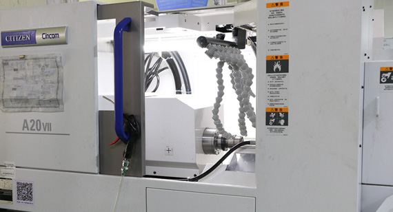
CNC machining, or Computer Numerical Control machining, is a versatile manufacturing process that utilizes computerized controls to automate the operation of machine tools. This technology enables the production of intricate parts with high precision and repeatability. CNC machines interpret computer-aided design (CAD) files to guide the cutting tools and create the desired shape from various materials such as metal, plastic, or wood.
Dimensional Tolerances in CNC Machining
Dimensional tolerances refer to the acceptable variations in the size and shape of machined parts. These tolerances are specified in the form of upper and lower limits, ensuring that the dimensions of the finished parts fall within the desired range. Factors such as material properties, machine capabilities, and design requirements influence the selection of dimensional tolerances. Achieving tight dimensional tolerances is crucial for ensuring proper fit and assembly of the components.
1. Importance of Dimensional Tolerances
Dimensional tolerances are vital in CNC machining as they directly impact the functionality and performance of the final product. Precise tolerances ensure that parts fit together correctly, reducing the risk of misalignment or malfunction. Moreover, tight dimensional control enables the interchangeability of components, simplifying assembly processes and minimizing errors.
2. Common Dimensional Tolerances
Commonly used dimensional tolerances in CNC machining include:
H1. Hole Diameter Tolerance
The tolerance specified for the diameter of a hole, ensuring it falls within the desired range.
H2. Shaft Diameter Tolerance
The tolerance specified for the diameter of a shaft or cylindrical feature, ensuring it falls within the desired range.
H3. Length Tolerance
The tolerance specified for the overall length of a part, ensuring it falls within the desired range.
H3. Angle Tolerance
The tolerance specified for the angular deviation of a feature, ensuring it meets the design requirements.
Geometric Tolerances in CNC Machining
Apart from dimensional tolerances, geometric tolerances play a crucial role in ensuring the form, orientation, and location of machined features. Geometric tolerances provide a comprehensive framework for controlling various aspects of a part's geometry beyond just its size. These tolerances define the allowable variations in features such as flatness, perpendicularity, parallelism, and circularity.
1. Importance of Geometric Tolerances
Geometric tolerances are essential in CNC machining as they enable designers to specify more complex part requirements. By controlling the form, orientation, and location of features, geometric tolerances ensure proper functionality, assembly, and interchangeability of parts. They also help achieve better performance and reliability in the final product.
2. Common Geometric Tolerances
Commonly used geometric tolerances in CNC machining include:
H1. Flatness Tolerance
The tolerance specified for the flatness of a surface, ensuring it falls within the desired range.
H2. Parallelism Tolerance
The tolerance specified for the parallelism between two surfaces or features, ensuring they remain within the desired range.
H3. Perpendicularity Tolerance
The tolerance specified for the perpendicularity between two surfaces or features, ensuring they meet the desired requirements.
H4. Circularity Tolerance
The tolerance specified for the circularity of a feature, ensuring it falls within the desired range.
Surface Roughness in CNC Machining
Surface roughness refers to the irregularities present on the surface of a machined part. It quantifies the deviations from the ideal smooth surface and is often measured in terms of Ra (average roughness) or Rz (mean roughness depth). Achieving the desired surface roughness is essential for functional and aesthetic reasons, as it affects factors such as friction, wear resistance, and appearance.
1. Importance of Surface Roughness
Surface roughness significantly impacts the performance and quality of machined parts. In applications where sliding or rotational motion is involved, such as bearings or sealing surfaces, a low surface roughness is crucial to reduce friction and prevent premature wear. Additionally, surface finish plays a vital role in determining the aesthetic appeal of a product.
2. Specifying Surface Roughness
Surface roughness is specified using various standards and symbols, such as Ra and Rz values. These values define the acceptable limits for deviations from the ideal surface. Finishing operations, tool selection, and machining parameters are carefully adjusted to achieve the desired surface roughness.
Relationship between Dimensional Tolerances, Geometric Tolerances, and Surface Roughness
In CNC machining, there is a close relationship between dimensional tolerances, geometric tolerances, and surface roughness. The dimensional and geometric tolerances specified for a part directly influence the achievable surface finish. Tighter tolerances and more stringent geometric requirements often result in the need for finer surface finishes. Conversely, looser tolerances may allow for slightly rougher surfaces.
Importance of Proper Tolerances in CNC Machining
Proper tolerance selection and control are critical for achieving high-quality machined parts. The right balance between functional requirements, manufacturing capabilities, and cost considerations must be maintained. Optimal tolerances ensure the parts fit and function as intended while avoiding excessive manufacturing costs.
Factors Affecting Tolerances and Surface Roughness
Several factors influence the achievable tolerances and surface roughness in CNC machining. Understanding these factors helps optimize the machining process and achieve the desired results. Some key factors include:
Material properties
Cutting tools and tooling selection
Machine accuracy and stability
Cutting parameters (speed, feed, depth of cut)
Fixturing and workholding techniques
Strategies for Achieving Tight Tolerances and Improved Surface Finish
To achieve tight tolerances and improved surface finish in CNC machining, several strategies can be employed:
Advanced machine tools with high precision and stability
Precision cutting tools and tool holders
Optimization of cutting parameters for each material and geometry
Proper fixturing and workholding to minimize vibrations and deflection
Effective use of coolant and lubrication
Post-machining operations such as polishing or grinding
Advanced Techniques for Dimensional and Geometric Control
In addition to conventional machining methods, advanced techniques can be employed for enhanced dimensional and geometric control. These include:
Multi-axis machining: Utilizing CNC machines with multiple axes to achieve complex geometries and tight tolerances.
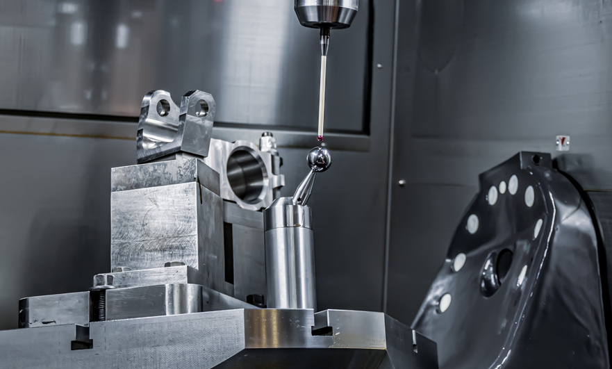
Coordinate measuring machines (CMM): Using CMMs to measure and verify the dimensional and geometric accuracy of machined parts.
Optical metrology: Employing optical measurement systems for precise surface characterization and inspection.
Benefits of Optimized Tolerances and Surface Roughness
Optimizing tolerances and surface roughness in CNC machining offers several benefits:
Enhanced functionality and performance of the final product
Improved aesthetics and customer appeal
Reduced friction and wear, leading to longer component life
Interchangeability and ease of assembly
Compliance with industry standards and regulations
Challenges in Maintaining Tolerances and Surface Quality
Maintaining tight tolerances and high surface quality in CNC machining can pose challenges. Some common difficulties include:
Machine and tool deflection
Thermal effects during machining
Material characteristics and variability
Part distortion due to residual stresses
Machining of complex geometries
Numerical relationship between shape tolerance and dimensional tolerance of CNC machined parts
When the dimensional tolerance accuracy of the CNC machined parts is determined, the shape tolerance has an appropriate value, that is, generally about 50% of the dimensional tolerance value is used as the shape tolerance value; about 20% of the dimensional tolerance value in the instrument industry is used as the shape tolerance value ;Heavy-duty industry takes about 70% dimensional tolerance value as shape tolerance value. This shows that. The higher the dimensional tolerance accuracy, the smaller the proportion of the shape tolerance in the dimensional tolerance. Therefore, when designing the size and shape tolerance requirements, except for special circumstances, when the dimensional accuracy of the CNC machined parts is determined, the 50% dimensional tolerance value is generally used as the shape Tolerance value, which is not only conducive to CNC manufacturing but also conducive to ensuring quality.
Numerical relationship between shape tolerance and position tolerance of CNC machined parts
There is also a certain relationship between the shape tolerance and position tolerance of CNC machining parts. From the perspective of the cause of the error, the shape error of the CNC machined parts is caused by machine tool vibration, tool vibration, spindle runout, etc.; while the position error is caused by the non-parallelism of the machine tool guide, the tool clamping is not parallel or perpendicular, and the clamping force From the perspective of the definition of tolerance zone, the position error includes the shape error of the measured surface. For example, the parallelism error contains the flatness error, so the position error is much larger than the shape error. Therefore, under normal circumstances, when there is no further requirement, the position tolerance is given, and the shape tolerance is no longer given. When there are special requirements, the shape and position tolerance requirements can be marked at the same time, but the marked shape tolerance value should be less than the marked position tolerance value, otherwise, the CNC machined parts cannot be manufactured according to the design requirements during production.
The relationship between the shape tolerance of CNC machined parts and the surface roughness
Although there is no direct connection between the numerical value and measurement between the shape error of the CNC machined parts and the surface roughness, there is a certain proportional relationship between the two under certain cnc processing conditions. According to experimental research, the surface roughness The degree occupies 1/5~1/4 of the shape tolerance.
It can be seen from this that in order to ensure the shape tolerance of CNC machining parts, the maximum allowable value of the corresponding surface roughness height parameter should be appropriately limited.
In general, the tolerance values among the dimensional tolerances, shape tolerances, position tolerances, and surface roughness of CNC machined parts have the following relationship: dimensional tolerance>position tolerance>shape tolerance>surface roughness height parameter.
It is not difficult to see from the numerical relationship between the size, shape and position of the CNC machined parts and the surface roughness, the numerical relationship of the three should be coordinated during the design. When marking the tolerance value on the drawing, it should be followed: given the roughness of the same surface The value should be smaller than its shape tolerance value; and the shape tolerance value should be smaller than its position tolerance value; the position differences should be smaller than its size tolerance value.
Otherwise, it will bring all kinds of troubles to manufacturing. However, the most involved in the design of CNC machining parts is how to deal with the relationship between dimensional tolerances and surface roughness and the relationship between various matching accuracy and surface roughness.
Under normal circumstances, it is determined according to the following relationship:
1. When the shape tolerance is 60% of the dimensional tolerance (medium relative geometric accuracy), Ra≤0.05IT;
2. When the shape tolerance is 40% of the dimensional tolerance (higher relative geometric accuracy), Ra≤0.025IT;
3. When the shape tolerance is 25% of the dimensional tolerance (high relative geometric accuracy), Ra≤0.012IT;
4. When the shape tolerance is less than 25% of the dimensional tolerance (super high relative geometric accuracy), Ra≤0.15Tf (shape tolerance value).
The simplest reference value: the dimensional tolerance of CNC machining parts is 3-4 times the roughness, which is the most economical.
Selection of the shape and position tolerance of CNC machining parts
The functions of comprehensive control items should be fully utilized to reduce the geometric tolerance items and corresponding geometric error detection items given on the drawings of CNC machining parts.
On the premise of meeting the functional requirements, the items of CNC machining parts that are easy to measure should be selected. For example, the coaxiality tolerance is often replaced by radial runout tolerance or radial runout tolerance. However, it should be noted that radial circle runout is a combination of concentricity error and cylindrical shape error, so when replacing, the runout tolerance value given should be slightly larger than the concentricity tolerance value, otherwise it will be too strict.
Selection of tolerance principles for CNC machining parts
According to the functional requirements of the tested elements, the tolerance function and the feasibility and economy of adopting the tolerance principle should be fully exerted.
The principle of independence is used in occasions where there is a big difference between the dimensional accuracy and the accuracy of the shape and position accuracy of the CNC machined parts, and the requirements must be met separately or the two are not connected to ensure the motion accuracy, sealing, and no tolerances.
Containment requirements are mainly used in occasions that require strict assurance of the nature of cooperation.
The largest entity requirement is used for the central element, and is generally used in occasions where the CNC machining parts require assemblability (no requirements for matching properties).
The minimum entity requirement is mainly used in occasions where the strength and minimum wall thickness of CNC machined parts need to be guaranteed.
The combination of reversible requirements and maximum (minimum) entity requirements can make full use of the tolerance zone, expand the actual size range of the measured element, and improve efficiency. It can be selected under the premise of not affecting the performance.
Selection of benchmark elements
1、Selection of reference parts
(1) Select the bonding surface of the CNC machined parts positioned in the machine as the reference part. For example, the bottom plane and side of the box, the axis of disc parts, the supporting journal or supporting hole of rotating parts, etc.
(2) The reference element should have sufficient size and rigidity to ensure stable and reliable positioning. For example, using two or more axes that are far apart to form a common reference axis is more stable than one reference axis.
(3) Choose the more accurate surface processed by cnc as the reference part.
(4) Try to make the assembly, cnc processing and testing standards unified. In this way, errors caused by inconsistent benchmarks can be eliminated; the design and manufacturing of fixtures and measuring tools for CNC machining parts can also be simplified, and the measurement is convenient.
2. Determination of the benchmark quantity
Generally speaking, the number of benchmarks should be determined according to the orientation and positioning geometric function requirements of the tolerance items of the CNC machining parts. Orientation tolerances mostly require only one datum, while positioning tolerances require one or more datums. For example, for parallelism, perpendicularity, and coaxiality tolerance items, generally only one plane or one axis is used as the reference element; for the position tolerance items of CNC machining parts, it is necessary to determine the position accuracy of the hole system, and two may be used. One or three benchmark elements.
3、Base order arrangement
When selecting two or more reference elements, the order of the reference elements must be clarified and written in the tolerance box in the order of first, second, and third. The first reference element is the main one, and the second reference element is the second.
4. Selection of shape and position tolerance value
The general principle: select the most economical tolerance value under the premise of satisfying the functions of CNC machining parts.
◆According to the functional requirements of CNC machining parts, considering the economy of machining and the structure and rigidity of CNC machining parts, determine the tolerance values of the elements according to the table. And consider the following factors:
1. The shape tolerance given by the same element should be less than the position tolerance value;
2. The shape tolerance value of cylindrical CNC machining parts (except for the straightness of the axis) should be less than its dimensional tolerance value; if on the same plane, the flatness tolerance value should be less than the parallelism tolerance value of the plane to the datum.
3. The parallelism tolerance value should be less than its corresponding distance tolerance value.
4. The approximate proportional relationship between the surface roughness of the CNC machined parts and the shape tolerance: Generally, the Ra value of the surface roughness can be taken as the shape tolerance value (20%~25%).
For the following situations, considering the difficulty of CNC machining and the influence of other factors besides the main parameters, to meet the requirements of the functions of CNC machining parts, appropriately reduce the selection of 1 to 2 levels:
○The hole is relative to the shaft;
○Slim and larger shafts and holes; shafts and holes with larger distance;
○The surface of parts with large width (more than 1/2 length);
○Tolerance of parallelism and perpendicularity of line-to-line and line-to-face relative to face-to-face.
5. Provisions for shape and position without tolerance
In order to simplify the drawing, the shape and position accuracy that can be guaranteed by the general machine tool CNC machining, it is not necessary to inject the shape and position tolerances on the drawings of the CNC machining parts, and the shape and position without tolerance shall be implemented in accordance with the provisions of GB/T1184-1996. The general content is as follows:
(1) Three tolerance levels of H, K, and L are specified for straightness, flatness, perpendicularity, symmetry and circular runout without marking.
(2) The uninjected roundness tolerance value is equal to the diameter tolerance value, but cannot be greater than the uninjected tolerance value of radial circle runout.
(3) The tolerance value of uninjected cylindricity is not specified, and it is controlled by the injection or uninjected tolerance of the roundness tolerance, the straightness of the element line and the parallelism of the relative element line.
(4) The unmarked parallelism tolerance value is equal to the larger of the dimensional tolerance between the measured element and the reference element and the unmarked tolerance value of the measured element shape tolerance (straightness or flatness), and take two The longer of the elements serves as the benchmark.
(5) The tolerance value of coaxiality is not specified. If necessary, the unmarked tolerance value of coaxiality can be equal to the unmarked tolerance of circle runout.
(6) The tolerance values of uninjected line profile, surface profile, inclination, and position are all controlled by the injection or uninjected linear dimensional tolerance or angle tolerance of each element.
(7) The total runout tolerance value is not specified.
6. Graphic representation of the shape and position without tolerance value
If the unmarked tolerance value specified in GB/T1184-1996 is used, the standard and grade code should be noted in the title column or technical requirements.
: "GB/T1184-K".
There is no “tolerance principle in accordance with the working tolerance of GB/T 4249” on the drawings of CNC machining parts, and the requirements of “GB/T 1800.2-1998” should be implemented.
Future Trends in CNC Machining
As technology advances, several trends are shaping the future of CNC machining:
Integration of artificial intelligence and machine learning for process optimization and predictive maintenance.
Development of additive manufacturing techniques to complement subtractive machining processes.
Enhanced precision and accuracy through improved machine design and control systems.
Increased automation and robotics for higher productivity and efficiency.
Conclusion
CNC machining is a sophisticated manufacturing process that relies on precise dimensional and geometric control as well as achieving the desired surface roughness. The relationship between dimensional tolerances, geometric tolerances, and surface roughness is crucial in ensuring the functionality, performance, and aesthetic appeal of machined parts. By understanding these relationships and employing appropriate strategies, manufacturers can optimize their CNC machining processes, resulting in high-quality products.
FAQs
Q1. Can CNC machining achieve extremely tight tolerances?
Yes, CNC machining can achieve extremely tight tolerances, depending on factors such as machine capabilities, material properties, and design requirements. Advanced CNC machines and techniques, such as multi-axis machining and optical metrology, can further enhance precision and control.
Q2. How does surface roughness affect the performance of machined parts?
Surface roughness affects factors such as friction, wear resistance, and sealing capabilities. A smoother surface with lower roughness reduces friction and wear, leading to improved performance and longer component life.
Q3. What are some common methods for measuring surface roughness?
Common methods for measuring surface roughness include profilometers, which use a stylus to measure surface irregularities, and optical techniques such as interferometry or confocal microscopy.
Q4. What are the challenges in maintaining tight tolerances in CNC machining?
Challenges in maintaining tight tolerances include machine and tool deflection, thermal effects, material variability, part distortion, and machining complex geometries. These challenges require careful process planning, tool selection, and machining parameter optimization.
Q5. How can CNC machining benefit from the integration of artificial intelligence and machine learning?
Artificial intelligence and machine learning can optimize CNC machining processes by analyzing vast amounts of data, identifying patterns, and making real-time adjustments to machining parameters. This integration can improve efficiency, productivity, and overall process control.

 +86 15099911516


 Read more