15 years one-stop China custom CNC machining parts factory

Hey there I’m VMT Sam!
With 25 years of CNC machining experience we are committed to helping clients overcome 10000 complex part-processing challenges all to contribute to a better life through intelligent manufacturing. Contact us now
 175 |
Published by VMT at Oct 30 2021
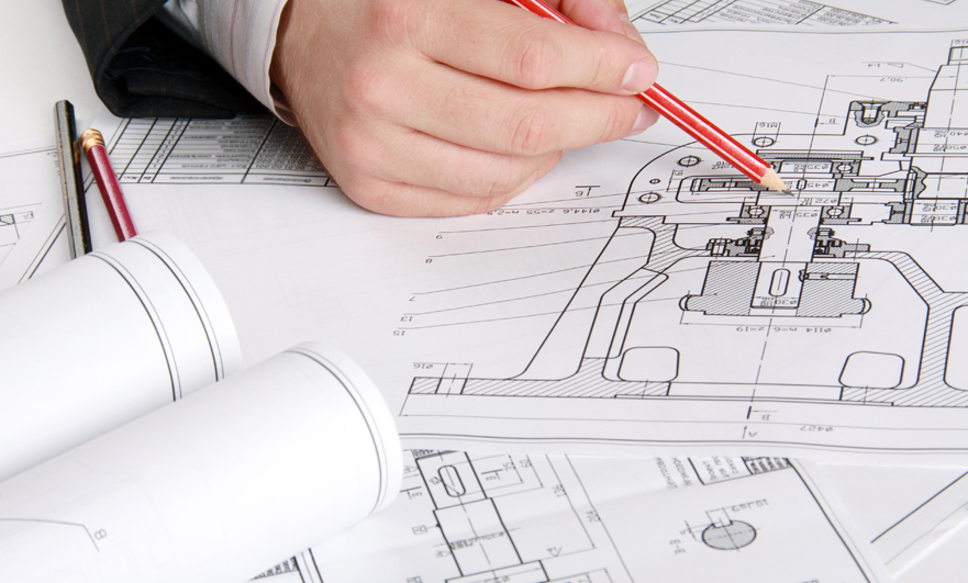
2D drawing machining and manufacturing is still widely used in CNC machining services. This is because most of them are NC machined parts graphics generated by three-dimensional models and numbers that have not been updated. These parts are usually CNC machined parts, sheet metal machining or components, because when they were first produced, CAD did not exist, and for a long time, resulting in poor original quality, repeated scanning leading to reduced resolution, and incomplete technical data.
With the emergence of the digital RFQ market for X-ray technology, X metrology application engineers have seen a wide range of CNC machined parts that need to be quoted, and capable CNC machined manufacturers can manufacture and complete parts to become a reality. These parts are usually mechanical parts, sheet metal manufacturing or components.
Mistake 1: Unrecognizable drawings
When the old drawing is finally scanned into a digital file, there is no guarantee that the drawing used is the original drawing. It is a copy in itself and a series of copies. Each copy will result in the loss of some data or details, so it may require careful identification to figure out the notes or size. When reviewing 2D technical drawings, CNC machining manufacturers must first find out if there are any unreadable or ambiguities that need to be clarified.
An example of this error is when the icon is scanned, cutting off critical information on the edges, such as title blocks or annotations. This is common for large graphics that cannot be scanned at once. Either way, the part may require some reverse engineering to find a better copy or make a brand new version of the file. The general rule of thumb is that if you can’t read the drawings, neither can the CNC machining manufacturer.

Mistake 2: Provide assembly drawings without part details
Another challenge with legacy components is that they may actually be upper-level components of several discrete mechanical components. Assembly drawings are usually used to define the relationship between each part of the assembly and other parts. This can include the number of each component, the unique name of each component, how many parts each component requires, and possibly some smaller distances or suitable verification metrics. One thing a buyer or engineer can check when purchasing an assembly is whether the technical specifications of each component are listed on the drawing. Unfortunately, if the manufacturer needs to manufacture sub-components of the component, this will not help the CNC machining manufacturer. Manufacturers need detailed CNC machining design drawings of each part to correctly process and manufacture parts.
Mistake 3: Incomplete drawings
Among CAD-controlled drawings, the best practice is to provide 3D and CAD models, which will be used to supplement key tolerances, threads, features, surface treatments, etc., to print with 2D drawings. The 3D CAD model is sufficient for the geometry of most parts, and supplementary drawings can provide part details. When only plan drawings (such as PDF or hand-drawn sketches) are provided to CNC machining manufacturers, the information must be complete. Each hole position, fillet, characteristic distance, thread, depth, etc.
should be referenced. It marks a paradigm shift between older, 2D drawing printing and newer, CAD-controlled drawings. In traditional drawings, it may be a canonical call to unpublished internal documents. Manufacturers usually view the part first, then the title bar, then the comments, and then repeatedly check whether all the information can be used to produce the CNC machining project.
When using old drawings, scans or freehand sketches, please check the following before submitting to the CNC machining manufacturer:
Title bar information:
1. CNC machining part name, part number and version
2. Unit scale (inch, millimeter, etc.)
3. Title block tolerance (for example, according to ASME Y14.5-2009)
4. Drawing perspective, such as the third angle projection
5. Number of pages and pages (check for missing pages)
Specific information of CNC machining parts:
1. Appropriate drawing views and dimensions for each feature
2. Datum, GD&T or key tolerance
3. Thread marking with size, tolerance grade and depth
Numbered comment part:
1. Material and alloy grade or specification
2. Precautions and requirements for coating or finishing
3. Edge fracture requirements
4. Other related notes and marking indicators on the drawing
In conclusion
After determining the project cost of CNC machining parts, first make sure that the drawings are clear and easy to read, mark specific information, provide all the drawings needed to assemble the components, and ensure that the CNC machining parts data exist, which will help the data machining manufacturer see you To understand your project requirements in time, and quickly and accurately quote you.
Ready To Start Your Next Project?
Get Instant Quote

Request a Free Quote
Send us a message if you have any questions or request a quote. We will get back to you ASAP!