15 years one-stop China custom CNC machining parts factory

Hey there I’m VMT Sam!
With 25 years of CNC machining experience we are committed to helping clients overcome 10000 complex part-processing challenges all to contribute to a better life through intelligent manufacturing. Contact us now
 812 |
Published by VMT at Sep 16 2022
When we use CNC machining, we often find that the outer circle of CNC machining parts has a taper phenomenon, which makes the diameters at both ends of the workpiece size inconsistent, which exceeds the tolerance range. So, what is the reason for the taper of the outer circle of CNC machined parts? How can we solve the problem of the taper of the outer circle of CNC machined parts?
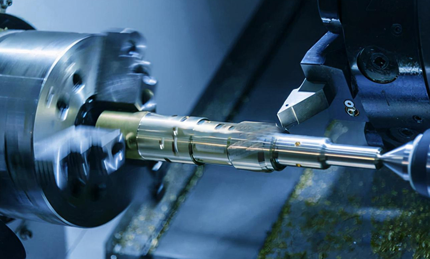
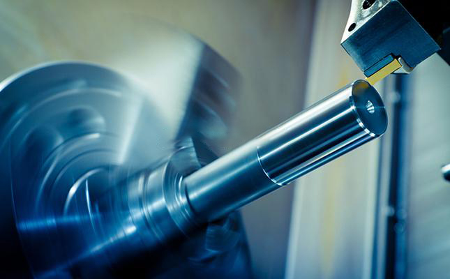
CNC machining is a machine tool that uses a CNC system. It uses turning tools to process revolving workpieces. It is suitable for cutting workpieces such as shafts and discs. It has comprehensive features such as high performance and high precision. Ordinary lathes are extensive and easier to operate than ordinary lathes. You only need to prepare the processing program in advance. After entering the program once, press the start button to automatically process, and the operator only needs to clamp and unload the workpiece. Can.
When CNC machining parts, the process selection is improper or slightly deviated, which will easily cause taper to the outer circle of the workpiece, which will increase the difficulty of CNC lathe processing and affect work efficiency. In actual operation, we can eliminate the problem of taper on the outer circle of the part by strictly controlling the CNC machining process, so as to ensure that the daily production CNC machining work is more convenient. The following will briefly introduce the solution to the taper on the outer circle of CNC machining parts.

The solution to the taper on the outer circle of CNC machining parts
1. Adjust the parallelism of the bed guide rails
The reason why the outer circle of CNC machined parts is tapered may be that the four corners of the lathe and the adjustment pads are loose, which will cause serious deviations in the horizontal straightness and vertical inclination of the guide rail surface, and even show a twisted state. The phenomenon that the outer circle of the workpiece is tapered, which affects the accuracy of CNC machining parts. Once this phenomenon occurs, we need to make correct adjustments to the four corners of the lathe, horns, etc., and also correct the horizontal straightness and vertical inclination of the guide rail surface of the bed.
2. Adjust the tailstock
Before CNC machining parts, if the coaxial alignment of the tailstock and the spindle axis is not corrected, no matter whether it is one clamp and one top, or two tops fixed to support the workpiece, the phenomenon of offset will occur, causing the outer circle of the workpiece to have a taper problem. If the outer circle of the part is tapered, we can measure the taper of the outer circle of the part first, and then determine the moving direction and distance of the tailstock according to the measurement results. Then carry out trial machining and re-measure the dimensions of both ends of the part to check whether the taper is eliminated. If the requirements of the CNC machining process are still not met, the tailstock can be readjusted, and the trial machining and measurement can be continued until the process requirements are met.
3. Adopt heavy-duty high-precision rotary top
Usually, the center of the CNC lathe tailstock will use the movable center to support the fixed workpiece. The sliding friction between the movable top and the center hole will be transformed into the rolling friction of the inner bearing of the top, and there is no relative movement between the top and the center hole. Therefore, the movable top can withstand high rotational speed, but its centering accuracy and rigidity are relatively poor. If it is used for workpieces with low precision requirements, the machining accuracy can reach the standard, but if it is used for workpieces with high precision requirements, the outer roundness of the workpiece will be deviated due to the problem of the runout of the movable center, resulting in the occurrence of taper. Phenomenon. Therefore, for CNC machining parts with high precision requirements, we can use heavy-duty high-precision rotary centers to meet the requirements of CNC machining technology.

4. Choose a reasonable tool angle
Cutting force refers to the resistance of the machined part when it resists the cutting of the tool. According to the difference of cutting force, it can be divided into three types: main cutting force, feed force, and depth of cut resistance. If the geometric angle of the tool is unreasonable, it will have a certain impact on the CNC lathe, increase the depth of cut resistance, and make the outer circle of the CNC machined parts tapered. When selecting the tool geometry angle, various indicators such as material and machining characteristics need to be considered. In this case, we can choose the main editor angle, because both the shape of the cutting area and the action direction of the cutting component force will change according to the change of the main editor angle, thus affecting the cutting force. The cutting thickness will increase with the increase of the main editor angle, which can effectively reduce the deformation of the cutting layer.
When the outer circle of CNC machined parts is tapered, first of all, the operator needs to determine the requirements of CNC parts, plus daily work experience, to analyze the reasons for the tapered outer circle of CNC machined parts. According to the analyzed reasons, make an adjustment to the lathe bed, tailstock, top, tool, etc., so as to avoid the phenomenon of taper on the outer circle of the workpiece, so as to ensure the size and accuracy of CNC machining parts.

The above is the summary of VMT CNC machining manufacturers. If you want to know more about the knowledge and application of CNC machining, please contact us to discuss with me.
Ready To Start Your Next Project?
Get Instant Quote

Request a Free Quote
Send us a message if you have any questions or request a quote. We will get back to you ASAP!