Mounting & Fitment Accuracy
Pivot bores, mounting holes, slots and mating faces are reviewed relative to the required datums so the finished component can assemble without unwanted looseness or interference.
Home / Product / Automotive Industry /
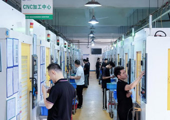
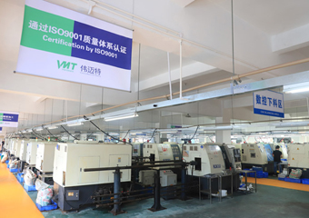
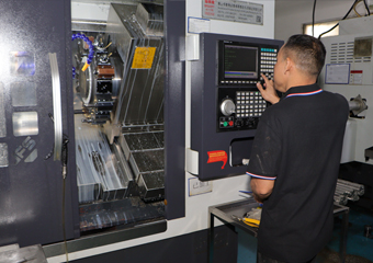
16 years of experience in CNC machining auto parts, different processing and manufacturing techniques, reducing processing costs. There are 2000+ automotive CNC machining parts samples, you can view the factory online, contact us immediately to get discounts and samples.
Product Specification:
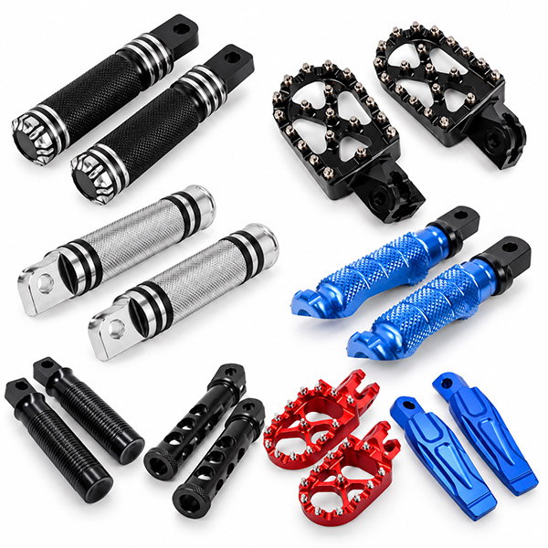
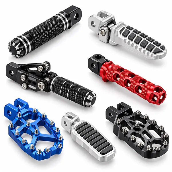
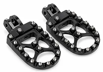
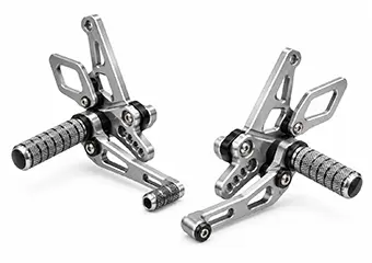
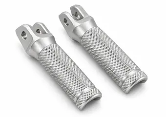
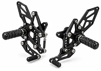
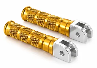
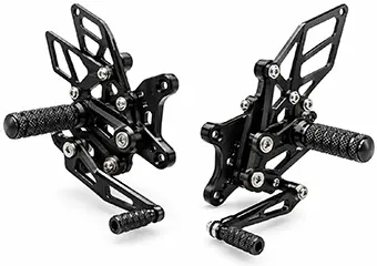
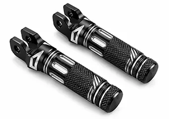
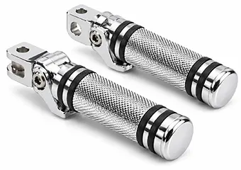
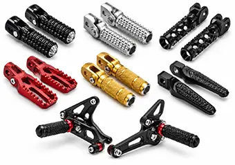
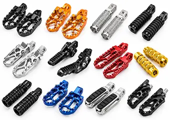
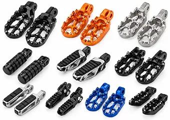
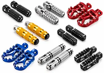
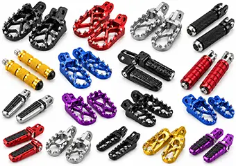
VMT manufactures custom motorcycle footrests and foot pegs from your drawings for fixed, folding, adjustable, racing, off-road and passenger applications. We coordinate DFM, CNC machining, anodizing, critical-dimension inspection and prototype-to-repeat-production control as one manufacturing process.

A motorcycle footrest is not only a machined aluminum part. Mounting geometry, pivot clearance, platform structure, grip features and surface finishing all influence whether the finished component fits, moves and repeats consistently.
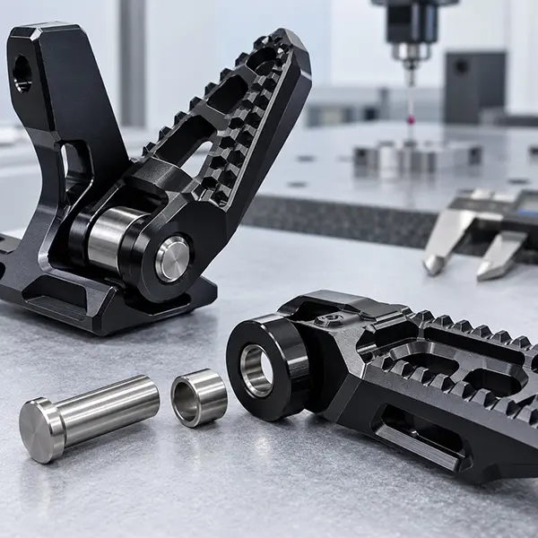
Pivot bores, mounting holes, slots and mating faces are reviewed relative to the required datums so the finished component can assemble without unwanted looseness or interference.
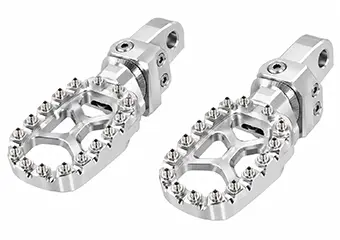
Platform width, serrations, teeth and threaded grip pins are planned around the intended contact geometry, machining access and edge condition.
Lightweight pockets, ribs and thin sections are reviewed for tool access, wall thickness and machining stability before material is removed.
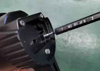
Critical bores, threads and mating areas are identified before anodizing so allowance, masking or post-finish inspection can be planned where required.
VMT manufactures custom motorcycle foot pegs according to customer CAD drawings, approved samples and functional requirements rather than selling one standard retail design.

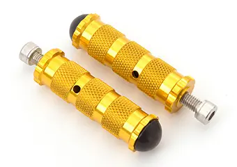
Fixed motorcycle foot pegs for street and OEM applications use 3/4-axis CNC milling to control mounting faces, platform geometry and grip features, with dimensional inspection confirming reliable assembly and repeatable production.

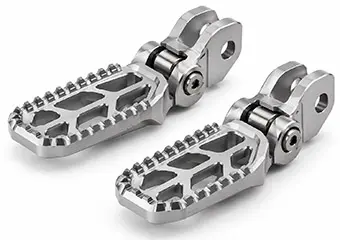
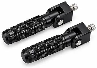
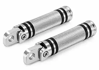
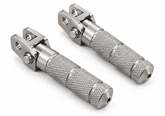
Folding motorcycle foot pegs for rider and passenger applications use CNC milling and turning to control pivot bores, stop surfaces and side clearance, with inspection confirming smooth movement and stable fit.

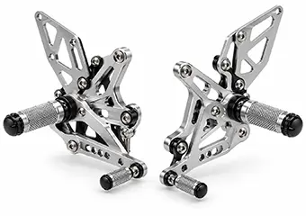
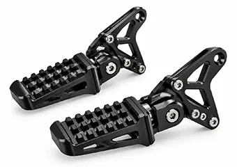
Adjustable motorcycle footrests for street and performance applications use multi-axis CNC milling to machine holes, slots and offsets, with position control and inspection supporting repeatable rider adjustment and assembly.

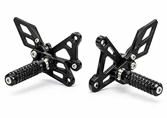
Racing motorcycle foot pegs for motorsport applications use 5-axis or multi-axis CNC milling to create lightweight pockets and aggressive grip geometry, with critical inspection confirming fit, strength and repeatable production.

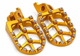
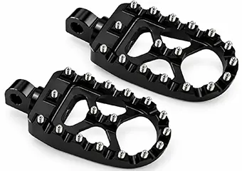
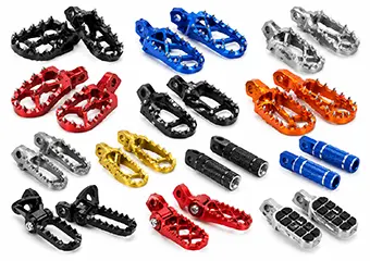
Off-road and dirt bike foot pegs use CNC milling for wide platforms, mud-clearance pockets and replaceable grip features, with dimensional and visual inspection supporting durable fitment in demanding terrain.

Passenger motorcycle foot pegs use CNC milling and turning for folding bodies, pivots and mating features, with edge, fit and cosmetic inspection delivering safe assembly and consistent finished appearance.

Wide platform foot pegs for adventure and off-road applications use CNC milling to control large support surfaces, ribs and pockets, with flatness inspection confirming stable geometry and repeatable production.

Custom foot pegs for OEM and aftermarket programs use drawing-based CNC milling, turning or multi-axis machining to control non-standard interfaces and grip geometry, with inspection validating fit and customer requirements.
A foot peg can look correct but still fail during assembly if the relationships between critical features are not controlled. We identify the functional datums and inspection points from your drawing before machining.
Bore size, roundness and alignment influence folding movement, pin fit and side play.
Mounting features are controlled relative to drawing datums so the part aligns with the mating bracket.
Machining sequence and workholding are selected to reduce distortion after heavy pocketing.
Angled mounting and platform features are referenced to defined datums for consistent installed geometry.
Tooth profile, pitch, height and edge condition are controlled according to the drawing.
Pocket depth, wall thickness, ribs and machining order are reviewed for stability.
Thread size, depth and position are checked for grip pins, fasteners and replaceable features.
Mirrored parts use common datum, fixture and inspection strategies to improve pair consistency.
Many problems appear only after machining, anodizing or assembly. We review these risks before repeat production so the approved prototype can be converted into a more repeatable manufacturing process.
Bore tolerance, mating pin size and coating buildup can change the final clearance.
Pivot bore alignment, side-face relationship, spacer dimensions or inadequate clearance can create binding or excessive play.
Small serrations and aggressive grip patterns require controlled toolpaths, tool condition and deburring.
Deep pockets, thin walls and uneven material removal can reduce rigidity during machining.
Coating buildup can reduce bore size or alter thread and mating behavior.
Alloy condition, machining texture and surface preparation can influence final anodized appearance.
Our engineering team reviews functional fits, machining access, material removal, finishing allowance and inspection requirements before programming so risks can be identified early.
Machine configuration, datum planning, workholding and finishing operations are selected according to the geometry and function of the foot peg rather than part size alone.

3/4-axis CNC milling is used for foot peg bodies with platforms, pockets, slots and side features, supporting efficient multi-face machining for street, racing and aftermarket applications.

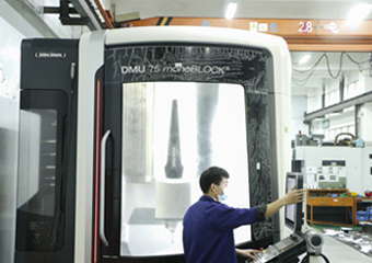
5-axis CNC machining is used for complex foot peg geometry with angled surfaces and difficult mounting features, reducing reclamping while supporting racing, premium aftermarket and lightweight performance applications.

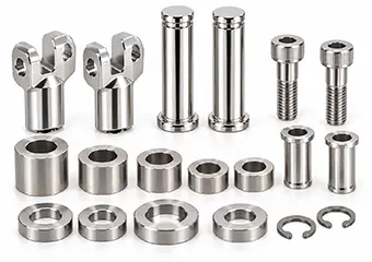
CNC turning is used for pivot pins, bushings, spacers and cylindrical interfaces, providing stable diameters and concentric relationships for folding, adjustable and precision motorcycle foot peg assemblies.

Turn-mill machining combines turning and milling for rotational parts with flats, cross-holes, slots or off-axis features, supporting compact motorcycle foot peg assemblies with fewer setups and stronger datum consistency.
Material selection affects strength, weight, machinability, finishing response, wear and project cost. We focus the choice on the foot peg structure and final use rather than listing every material the factory can machine.

6061-T6 suits street, passenger and aftermarket foot pegs with balanced strength and machinability, anodizes consistently, and gives buyers a practical cost-to-performance choice for repeat production.

7075-T6 suits racing and lightweight foot pegs needing higher strength-to-weight performance, works with protective anodizing, and helps buyers reduce mass while retaining structural confidence.

Titanium Grade 5 suits premium racing and performance foot pegs with low weight, high strength and corrosion resistance, giving buyers a durable high-end option where cost is secondary.

Stainless steel suits pivot pins, bushings and wear interfaces needing strength and corrosion resistance, supports polishing or passivation, and improves long-term assembly durability for buyers.
Surface finishing affects more than appearance. On motorcycle foot pegs, coating and surface preparation can also influence critical bores, threads, mating fits and batch consistency.

Aluminum street and passenger foot pegs use Type II anodizing for corrosion protection and color control, giving buyers a clean, repeatable finish for visible production parts.

Performance aluminum foot pegs use hard anodizing for higher surface hardness and wear resistance, giving buyers better durability when functional fits are planned before finishing.

Visible aluminum foot pegs use bead blasting before anodizing for a uniform matte texture, giving buyers more consistent cosmetic appearance from approved samples to repeat batches.

Selected motorcycle foot pegs and brackets use powder coating for durable color coverage and corrosion protection, giving buyers a robust decorative finish where coating thickness is acceptable.

Premium aluminum foot pegs use polishing before anodizing for a smoother, brighter decorative surface, giving buyers stronger visual impact on branded or high-end custom components.

Selected performance foot peg components use PVD or DLC for wear-focused surfaces and premium appearance, giving buyers a specialized finish for demanding branded applications.

Custom motorcycle foot pegs use laser marking or engraving for logos, part numbers and traceability, giving buyers permanent identification without changing critical assembly dimensions.

Steel or selected motorcycle foot peg components use nickel or chrome plating for corrosion protection and bright metallic appearance, giving buyers durable decorative surfaces on suitable parts.
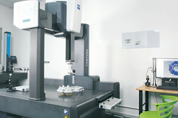
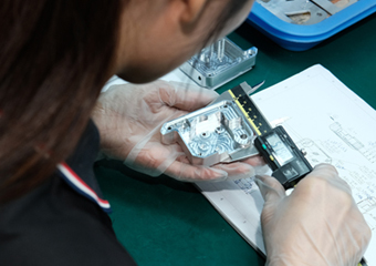
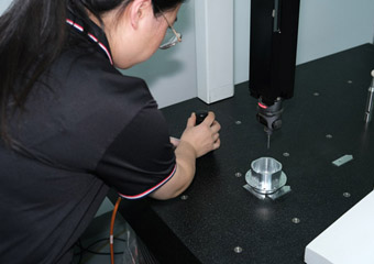
Inspection follows function, so VMT identifies the dimensions that directly control mounting, folding movement, rider position, grip features and final assembly instead of treating every dimension as equally critical. For agreed critical features, we can review machining capability down to ±0.005 mm and use CMM, bore gauges, thread gauges and inspection fixtures according to the drawing and functional datum structure.
Critical pivot bores, mounting positions, threads and post-finish fit areas can be defined for 100% inspection when the project requires it, while non-critical geometry keeps practical tolerances to avoid unnecessary machining and inspection cost.

| Critical Feature | What Can Go Wrong | VMT Control & Verification |
|---|---|---|
| Pivot Bore & Pin Fit | Machining or coating variation can create binding, excessive play or unstable folding movement. | Review bore/pin clearance as an assembly; verify critical diameter with bore gauge or CMM and recheck finished condition when required. |
| Mounting Bore & Hole Position | A correct hole diameter can still fail assembly if its position shifts from the functional datum. | Program from drawing datums and verify critical position by CMM; agreed critical positions can receive 100% inspection. |
| Platform Flatness & Parallelism | Heavy pocketing or fixture pressure can release distortion after unclamping. | Use staged roughing/finishing and controlled support, then verify flatness or parallelism in the released condition. |
| Foot Peg Angle | Angular error can change installed rider position or mating-bracket relationship. | Verify the angle against drawing datums by CMM or a dedicated inspection fixture. |
| Serration / Tooth Geometry | Tool wear and deburring can change tooth height, edge condition or grip consistency. | Control the programmed geometry and inspect agreed dimensions together with visual burr and edge acceptance. |
| Thread Size & Depth | Undersized, damaged or coated threads can stop grip pins and fasteners from assembling. | Use suitable GO / NO-GO gauges and protect or re-verify critical threads after finishing where required. |
| Post-Anodize Fit Areas | Coating growth can tighten bores or change the effective size of mating features. | Define pre-finish allowance, masking and final-condition inspection before production release. |
| Left / Right Pair Consistency | Mirrored parts can drift in angle, position or cosmetic appearance between sides. | Use common datum logic, controlled fixtures and paired inspection criteria for repeat-production consistency. |
| Cosmetic Surface | Scratches, color variation, rack marks or inconsistent texture can fail appearance acceptance even when dimensions pass. | Use visual inspection against the approved cosmetic standard, color reference and defined A-surfaces before final packing. |

Verify drawing-defined bores, mounting relationships and functional dimensions.

Check grip-pin threads, mounting threads and other assembly-critical features.

Measure complex datum relationships, position and geometry where required.
A first sample is not production-ready simply because it matches the CAD. Fitment, movement, post-finish dimensions and cosmetic requirements should be validated before repeat manufacturing.
Review CAD, material, finishing, critical dimensions and mating interfaces.
Produce engineering samples using the planned datum and machining strategy.
Verify mounting, pivot, thread and other drawing-defined critical features.
Confirm installation, folding movement, rider position and mating-part clearance.
Update drawing or process requirements if prototype testing identifies a required change.
Establish the reference for dimensional, functional and cosmetic requirements.
Verify manufacturing stability, finishing consistency and inspection criteria.
Maintain approved programs, fixtures, finishing and quality requirements.
Foot peg geometry changes with riding position, load, grip requirement, terrain and brand design language. We manufacture the structure around the customer’s application rather than offering one universal design.

Racing and motorsport programs use lightweight CNC foot pegs with aggressive grip and compact geometry, giving performance brands lower mass, precise fitment and repeatable production for demanding riding conditions.

Street and performance motorcycle programs use adjustable CNC footrests with controlled fit and premium finishes, giving brands reliable assembly, refined appearance and flexible rider-position options for aftermarket or OEM projects.

Off-road and dirt-bike programs use wide-platform CNC foot pegs with mud-clearance pockets and aggressive grip, giving brands stronger rider support, durable terrain performance and replaceable traction features.

Adventure motorcycle programs use wide, lightweight CNC foot pegs with durable grip and reinforced geometry, giving brands stable rider support, long-distance comfort and dependable performance across mixed road conditions.

Custom and aftermarket brands use drawing-based CNC foot pegs with unique geometry, branded finishes and tailored mounting interfaces, giving product teams differentiation, controlled fitment and scalable repeat production.

Electric motorcycle and E-Moto programs use lightweight custom CNC footrests with platform-specific mounting geometry, giving new vehicle brands reduced mass, accurate integration and flexible development from prototype to production.
Folding motorcycle foot pegs depend on the relationship between the pivot bore, mating pin, side clearance and finished surface condition. VMT reviews these features together so anodizing does not create unexpected binding, looseness or assembly problems.

A pivot bore can meet the machining drawing before finishing but become too tight after anodizing adds thickness to the functional surface. If clearance is too small, the foot peg may bind during folding; if it is too large, the assembly can develop unwanted side play.
We review the pivot bore, mating pin, side-face relationship and required movement as one functional system. Depending on the drawing, the process may use pre-finish allowance, masking, controlled machining tolerances or post-anodize inspection to maintain the required final fit.
The goal is not only to make the first prototype assemble correctly. By defining the finished-condition fit before production, the same pivot relationship can be repeated more consistently across pilot batches and future orders, reducing manual adjustment and rework.
The manufacturing value is not only machine capacity. It is the ability to turn a drawing into a manufacturable, inspectable and repeatable process from prototype through later production.
Review machining access, fit relationships, tolerance requirements and finishing risks before production.
Fast quotation response when drawings, material, finish and quantity are sufficiently defined.
3-axis, 4-axis, 5-axis milling, CNC turning and supporting processes for prototype and repeat production.
Engineering samples, pilot batches and repeat orders can follow one confirmed manufacturing route.
Available for drawing-defined critical dimensions where the geometry and process require it.
Material verification, in-process checks, CMM, finishing control and final inspection support.
The clearer the functional and cosmetic requirements are, the faster the engineering team can review manufacturability and prepare a useful quotation.
This published VMT motorcycle project shows how cosmetic geometry, bearing fit and delivery requirements were reviewed together before production.

The curved R-angle had to maintain a clean cosmetic appearance, while the bearing location required a tight and reliable fit because the assembly relationship affected brake sensitivity.
After receiving the 3D files and signing the confidentiality agreement, VMT discussed the technical requirements with the customer and reviewed whether the selected process could meet machining and delivery requirements.
The case demonstrates why visible motorcycle parts still need functional fit control: appearance, bearing or pivot interfaces, machining route and delivery planning should be solved as one manufacturing project.
Across VMT’s published customer feedback, buyers most often highlight finished-part quality, smooth sample-to-production transitions, protective packaging and responsive follow-up. The comments below show the practical cooperation points OEM, engineering and sourcing teams tend to value after working with VMT.

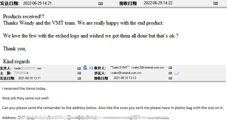
Customer feedback after completed deliveries has included: “We are really happy with the end product.” Other project feedback has also described parts as perfect and machining quality as excellent.

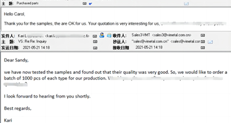
After sample validation, one customer wrote: “Your parts were perfect, thank-you. I want to order a production quantity soon.”

Packaging feedback has included: “Every part was securely packed and easy to access.” Cosmetic parts can be packed to reduce scratches and part-to-part contact.

Repeat-project feedback has included comments such as “The parts look great,” together with follow-up shipment and future-order requests.
Use this guide to work through the decisions that usually determine whether a custom foot peg moves smoothly from drawing review to prototype validation and repeat production.
“Footrest” and “foot peg” are often used for the same rider or passenger support component, although foot peg usually describes a peg-style or toothed platform while footrest can also include wider or folding support designs. For a CNC supplier, the name is less important than the functional definition.
The drawing should make the mounting interface, pivot relationship, installed angle, grip features, mating components and visible surfaces clear. This prevents a project from being quoted as a simple aluminum part when it is actually a moving or assembly-critical motorcycle component.
6061-T6 is usually the practical starting point for street, passenger and general aftermarket foot pegs because it machines efficiently, anodizes consistently and keeps material and machining cost under control. It is often the better choice when the geometry already provides enough section thickness and stiffness.
7075-T6 becomes more useful when a racing or lightweight design needs higher strength-to-weight performance, thinner sections or deeper weight-reduction pockets. The trade-off is higher material cost and a less forgiving manufacturing route, so the decision should be based on load, wall thickness, weight target, finishing requirement and repeat-production cost rather than alloy strength alone.
A folding mechanism depends on the pivot bore, pin, side clearance, stop surface, spring interface and mounting bracket working together. A bore can measure correctly and the assembly can still bind if the datum relationship or side-face spacing is wrong.
During DFM, define the required movement and the final mating condition first. Then the supplier can decide which features should share a datum, which dimensions require tighter control and whether the fit applies before or after anodizing.
Aggressive teeth, serrations and replaceable grip pins improve rider contact, but very small pitch, sharp tips or poor cutter access can increase tool wear, burrs and inspection difficulty. The geometry should therefore be reviewed together with the intended machining and deburring method.
For replaceable pins, thread depth, wall thickness and access space matter as much as the visible tooth pattern. A manufacturable grip design gives the rider the intended traction without making repeat production dependent on excessive manual cleanup.
Deep pockets and thin sections can lower mass but also reduce rigidity during machining. When material is removed too aggressively, fixture pressure, residual stress or tool load can change flatness and geometry after the part is released.
A better lightweight strategy balances pocket depth, ribs, minimum wall thickness, internal radii and cutter reach. If high-volume production is expected, blank selection or a combined process route should also be considered instead of assuming every piece must be milled from solid stock.
Type II anodizing, hard anodizing, polishing, powder coating, PVD and plating do not affect every feature in the same way. Critical bores, threads and mating faces may require allowance, masking or a finished-condition inspection requirement.
Visible A-surfaces also need early planning because blasting, polishing, rack contact and logo location influence appearance. Buyers get more predictable samples and repeat batches when machining and finishing are treated as one process rather than two separate suppliers’ responsibilities.
Pivot bores, mounting positions, angular relationships and critical threads may justify tighter tolerances, while cosmetic pockets and non-mating external features often do not. Applying the same tight tolerance everywhere increases machining time and inspection cost without improving the rider’s experience.
During DFM, separate function-critical dimensions from general geometry and define the inspection method at the same time. This makes the tolerance meaningful because the supplier knows both what must be controlled and how the result will be verified.
Before releasing repeat production, validate mounting alignment, pivot movement, side clearance, stop position, platform angle, grip geometry, thread engagement, post-finish fit, left/right orientation and visible appearance. If these items are not captured in the approved standard, a visually correct prototype may still be difficult to reproduce consistently.
The approved drawing revision, CNC program, fixture strategy, finish specification and critical inspection points should then carry into pilot production. This is the step that turns a successful one-off prototype into a repeatable manufacturing solution.
Send VMT your drawing, material, finish, quantity, critical fit requirements and mating-component information. Our engineering team can review manufacturability, machining strategy, finishing risk and inspection requirements before quotation.
Related suggestionGive us a call or send an inquiry to our emailbox, we will answer your doubts according to your customers' requirements, and quote you immediately.