16 years one-stop China custom CNC machining parts factory

Hey there I’m VMT Sam!
With 25 years of CNC machining experience we are committed to helping clients overcome 10000 complex part-processing challenges all to contribute to a better life through intelligent manufacturing. Contact us now
 1411 |
Published by VMT at Jun 29 2022
1411 |
Published by VMT at Jun 29 2022


If you are a professional CNC machining lathe person, it is not difficult to understand the dimensions and professional symbols on the drawings of precision metal parts machining, but if you are initially exposed to the CNC machining industry, or you need to develop a project, The dazzling drawings may make you very big. If you can't understand the drawings, it is difficult to guarantee the efficiency and effect of many things. Today we will learn how to understand the drawings of precision metal parts machining:
1. Dimensions of common structures
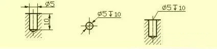
Dimensions of common holes (blind holes, threaded holes, countersunk holes, countersunk holes); dimensions of chamfers.
Blind hole
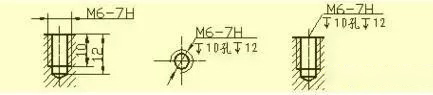
Threaded hole
Counterbore
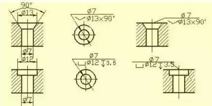
Spot Facing
Chamfer
2. Machining structure on CNC machining parts
Undercuts and wheel overruns
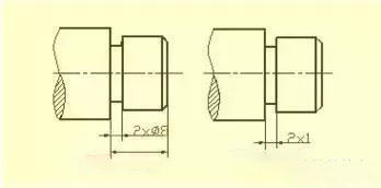
During the machining of CNC machining parts, in order to facilitate the withdrawal of the tool and ensure that the contact surfaces of the relevant parts are close during assembly, the undercut groove or the grinding wheel overrun groove should be pre-machined at the step of the machined surface.
The size of the undercut when turning the outer circle can generally be marked in the form of "groove width × diameter" or "groove width × groove depth". Grinding wheel overrun grooves when grinding external circles or grinding external circles and faces.
The blind hole drilled with a drill has a taper angle of 120° at the bottom, and the drilling depth refers to the depth of the cylindrical part, excluding the taper. At the transition of the stepped drilling, there is also a cone with a cone angle of 120°, its drawing method and dimensioning method.
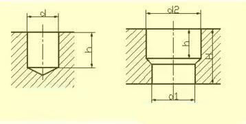
When drilling with a drill bit, the axis of the drill bit is required to be as perpendicular to the end face of the drilled hole as possible to ensure accurate drilling and prevent the drill bit from breaking. Correct construction of three drilled end faces.
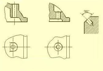
Bosses and pits
The contact surfaces of CNC machined parts with other parts are generally CNC machined. In order to reduce the processing area and ensure good contact between the surfaces of CNC machined parts, bosses and pits are often designed on castings. Bolted support surface bosses or support surface pits; in order to reduce the CNC machining area, a groove structure is made.
3. Common CNC machining parts structure
Shaft Parts
Such CNC machining parts generally include shafts, bushings and other parts. When expressing a view, as long as a basic view is drawn and appropriate cross-sectional drawings and dimensioning are added, its main shape features and local structures can be expressed. . In order to facilitate the viewing of drawings during CNC machining, the axis is generally projected horizontally, and it is best to choose the position where the axis is the vertical line.
When dimensioning the CNC machining parts of the bushing, its axis is often used as the radial dimension reference. From this, note the Ф14 and Ф11 shown in the figure (see A-A section) and so on. In this way, the design requirements and the process benchmarks during CNC machining are unified (when the shaft parts are CNC machined on the lathe, both ends are pressed against the center hole of the shaft with a thimble). The datum in the length direction is often selected from important end faces, contact surfaces (shoulders) or machined surfaces.
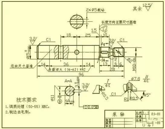
As shown in the figure, the right shoulder with a surface roughness of Ra6.3 is selected as the main dimension reference in the length direction, so dimensions such as 13, 28, 1.5 and 26.5 are injected; then the right shaft end is used as the length direction The auxiliary base of , thus marking the total length of the shaft 96.
Cover Parts
The basic shape of this type of parts is a flat disc, generally there are CNC machining parts such as end caps, valve covers, gears, etc. Their main structures are generally rotary bodies, usually with flanges of various shapes, evenly distributed. Local structures such as round holes and ribs. When selecting a view, generally select the sectional view of the symmetry plane or the axis of rotation as the main view, and at the same time, it is necessary to add other appropriate views (such as left view, right view or top view) to express the shape and uniform structure of the part. A left view has been added as shown to represent the square flange with rounded corners and four evenly spaced through holes.
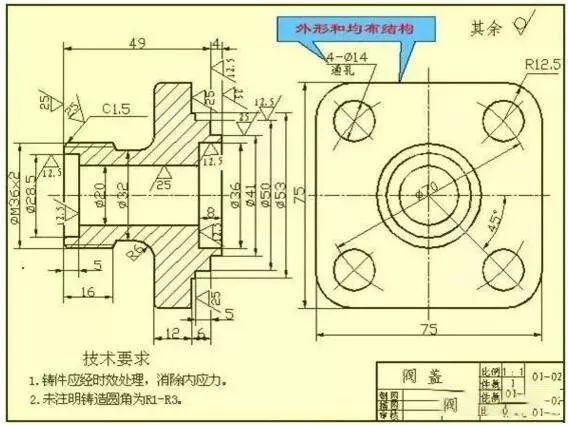
When dimensioning the CNC machined parts of the disc cover, the axis passing through the shaft hole is usually selected as the radial dimension reference, and the main dimension reference in the length direction is often selected as the important end face.
Fork parts
Such parts generally include shift forks, connecting rods, supports and other parts. Because their processing positions are changeable, when selecting the main view, the working position and shape features are mainly considered. For the selection of other views, two or more basic views are often required, and appropriate partial views, cross-sectional views, etc. are also used to express the local structure of the part. The view selection shown in the stepping seat part drawing is concise and clear. For expressing the width of the bearing and the rib, the right view is not necessary, but for the T-shaped rib, it is more appropriate to use the section. When marking the size of fork-like parts, the installation base surface or the symmetrical plane of the part is usually selected as the size reference.
Box Parts
Generally speaking, the shape and structure of this type of CNC parts are more complicated than those of the previous three types of parts, and the processing position changes more. Such parts generally include valve body, pump body, reducer box and other parts. When selecting the main view, the main consideration is the working position and shape features. When choosing other views, various auxiliary views such as cross-section, section, partial view and oblique view should be used according to the actual situation to clearly express the internal and external structure of the part.
In terms of dimensioning, the axis required by the design, the important installation surface, the contact surface (or processing surface), and the symmetry plane (width, length) of some main structures of the box are usually selected as the size benchmark. For the part of the box that needs to be cut, the size should be marked as far as possible according to the requirements for CNC machining and inspection.
The concept of surface roughness:
The micro-geometric shape characteristic composed of peaks and valleys with small spacing on the surface of CNC parts is called surface roughness. This is mainly due to the tool marks left by the tool on the surface of the part and the plastic deformation of the surface metal during cutting and splitting when CNC machining parts. The surface roughness of parts is also a technical index for evaluating the surface quality of parts. It has an impact on the matching properties, working accuracy, wear resistance, corrosion resistance, sealing performance and appearance of parts.
The evaluation parameters of the surface roughness of CNC parts are:
1) Contour arithmetic mean deviation (Ra)
Within the sampling length, the arithmetic mean of the absolute value of the contour offset.
2) The maximum height of the profile (Rz)
Within the sampling length, the distance between the top line of the profile peak and the bottom line of the profile peak. Remarks: Ra parameter is preferred when using.
Marking requirements for surface roughness:
1) Example of code labeling for surface roughness
When the surface roughness height parameters Ra, Rz, Ry are marked with numerical values in the code, except that the parameter code Ra can be omitted, the corresponding parameter code Rz or Ry must be marked before the parameter value.
2) Labeling of surface roughness The method of labeling the numbers and symbols of surface roughness on the drawing
A. The surface roughness code (symbol) should generally be marked on the visible contour line, dimension extension line or their extension, and the tip of the symbol must point from the outside of the material to the surface.
B. The direction of numbers and symbols in the surface roughness code must be marked according to regulations.
Annotation example for surface roughness:
On the same drawing, each surface is generally only marked with a code (symbol) once, and it should be as close as possible to the relevant dimension line. When the space is narrow or it is inconvenient to mark, the mark can be drawn out. When all surfaces of a part have the same surface roughness requirements, they can be uniformly marked on the upper right corner of the drawing. When most surfaces of the parts have the same surface roughness requirements, use the most code (symbol) for them At the same time, it can be noted in the upper right corner of the pattern, and the word "rest" can be added. The height of the uniformly marked surface roughness code (symbol) and explanatory text should be 1.4 times that of the drawing mark.
The surface roughness code (symbol) of the continuous surface on the CNC part, the surface of repeated elements (such as holes, teeth, grooves, etc.) and the same surface connected with discontinuity by thin solid lines is only noted once.
When there are different surface roughness requirements on the same surface, the dividing line shall be drawn with a thin solid line, and the corresponding surface roughness code and size shall be indicated. The working surface of the center hole, the working surface of the keyway, the chamfer, and the surface roughness code of the fillet can simplify the labeling. When partial heat treatment or partial plating (coating) of parts is required, the range shall be drawn with thick stippling lines and the corresponding dimensions shall be marked, or the requirements may be written on the horizontal line of the long side of the surface roughness symbol.
5. Standard tolerance and basic deviation
In order to facilitate production, realize the interchangeability of parts and meet different use requirements, the national standard "Limits and Fits" stipulates that the tolerance zone is composed of two elements: standard tolerance and basic deviation. The standard tolerance determines the size of the tolerance zone, while the basic deviation determines the location of the tolerance zone.
1) Standard Tolerance (IT)
The value of the standard tolerance is determined by the basic size and the tolerance class. Among them, the tolerance level is a mark to determine the degree of dimension. The standard tolerance is divided into 20 grades, namely IT01, IT0, IT1, ..., IT18. Its size degree decreases sequentially from IT01 to IT18. See the relevant standards for the specific numerical values of standard tolerances.
The basic deviation refers to the upper or lower deviation of the tolerance zone relative to the zero line position in the standard limit and fit, generally refers to the deviation close to the zero line. When the tolerance zone is above the zero line, the basic deviation is the lower deviation; otherwise, it is the upper deviation. There are 28 basic deviations in total, and the codes are expressed in Latin letters, the uppercase is the hole, and the lowercase is the shaft.
It can be seen from the basic deviation series diagrams: the basic deviation A~H of the hole and the basic deviation k~zc of the shaft are the lower deviation; the basic deviation K~ZC of the hole and the basic deviation a~h of the shaft are the upper deviation, JS The tolerance zone of js and js is symmetrically distributed on both sides of the zero line, and the upper and lower deviations of the hole and the shaft are +IT/2 and -IT/2 respectively. The basic deviation series chart only shows the position of the tolerance zone, not the size of the tolerance. Therefore, one end of the tolerance zone is an opening, and the other end of the opening is limited by the standard tolerance.
Basic deviation and standard tolerance, according to the definition of dimensional tolerance has the following calculation formula:
ES=EI+IT or EI=ES-IT
ei=es-IT or es=ei+IT
The tolerance zone codes of holes and shafts are composed of basic deviation codes and tolerance zone grade codes.

 +86 15099911516


 Read more