16 years one-stop China custom CNC machining parts factory

Hey there I’m VMT Sam!
With 25 years of CNC machining experience we are committed to helping clients overcome 10000 complex part-processing challenges all to contribute to a better life through intelligent manufacturing. Contact us now
 685 |
Published by VMT at Oct 25 2021
685 |
Published by VMT at Oct 25 2021


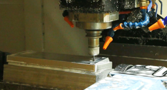
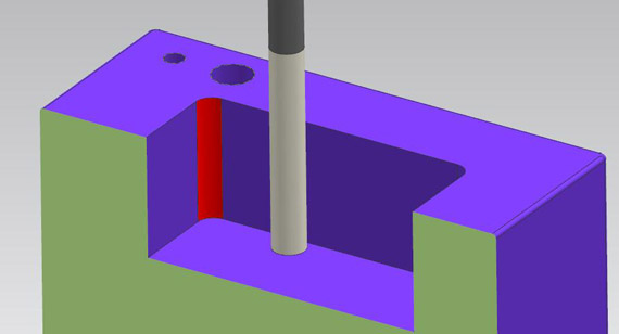
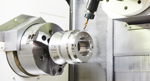
In the CNC machining process, it is faced with a series of different drawing document formats. We need to process them into programming, with the introduction of a fast working path diagram. This requires a wealth of processing experience to judge whether it can be generated through the CAM software to generate G code and use it for the machine.
Another situation is that post-processors need to be converted according to the linkage of CAM software and machines. It is also important to check whether they can be converted to each other according to different G code files.
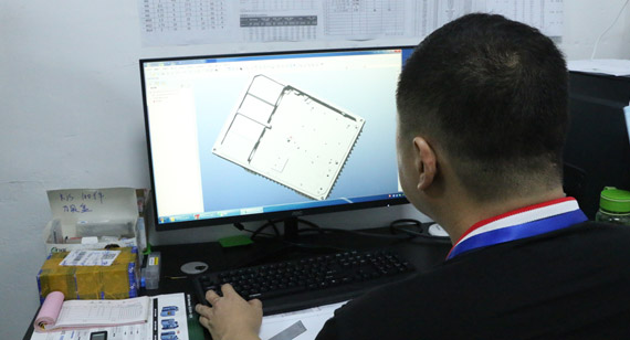
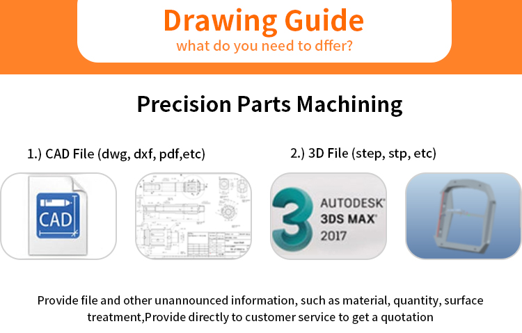
Drawing design document
Let's start with the design file. If you work in a creative field, you might use 3 types of files: 2D vector documents, raster documents, and 3D documents.
Vector document
A vector document refers to a graphic document that is described mathematically, and can be scaled arbitrarily by a computer without loss of details under the conditions of the original production software environment and library files. In contrast to raster documents composed of pixels, vector files are composed of objects, which makes it highly compatible with CAD software.
DXF
It is a CAD data file format used for CAD data exchange between AutoCAD and other software. If your design is a 2D vector image, the DXF file is especially important, and then you can use CAM software to instantly convert it to G code.
DWG
A proprietary file format used by AutoCAD and AutoCAD-based software to save design data. They are the native format of AutoCAD and have the advantage of supporting 2D and 3D images. But they cannot be transferred to other software.
SVG
SVG is an image file format. Its English full name is Scalable Vector Graphics, which means scalable vector graphics. SVG files have been developed for web-based work, such as web browsers and design applications. SVG They are not specifically used in CAD software, but they can be imported into Fusion360 to convert them into G code.
Raster file
Raster image files, also called raster graphics files or bitmap images, are used to store data in the form of a dot matrix structure to represent images. Common file extensions for raster files are *.png, *.jpg, or *.tiff. If you need to use raster files for CNC milling, you first need to vectorize the image to a usable extension before you can convert it to G code.
3D files
STEP format (*.step, *.ste, *stp) is used as the standard for 3D files. It will allow you to design your work in one CAD software and still be able to open it in another CAD software, even if some editing options may be lost between the software. However, you can always open the STEP file into CAM software such as Fusion360 to generate G code from it. If you are collaborating with other 3D creatives, we believe this is the best format for exchanging files for milling.
In addition to STEP files, different companies have their own file systems such as CATIA (*.CATProduct, *.CATPart), SketchUp (*.skp), Inventor (*.ipt, *.iam) or Fusion 360 Archive (*. f3d), Solidworks (*.prt, *.asm, *.sldprt, *.sldasm).
G code file (processing file)
G code files are always very simple text files with command lines. The choice of file extension depends on which one will be compatible with the CNC machine (or other hardware) you are using. A special problem with G-Code files is that you cannot convert one g-code file to another: CAM software cannot open the G-Code file in the reverse direction so that it passes through another post-processor compatible with your machine. Therefore, when sharing CNC works, please make sure to always share CAD or vector files and generate G-Code yourself.
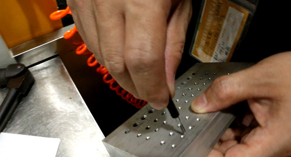
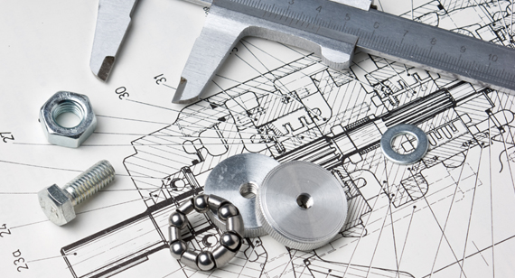
Before custom machining parts, CNC machining manufacturers will let our customers provide 2D vector files and 3D drawing files, so that we can accurately judge customer drawing parts tolerance, surface roughness and other issues, and provide customers with suggestions and discussions. The clearer the drawing, the more clearly the manufacturer will know your needs, the more accurate the quotation and the cost savings.

 +86 15099911516


 Read more