16 years one-stop China custom CNC machining parts factory

Hey there I’m VMT Sam!
With 25 years of CNC machining experience we are committed to helping clients overcome 10000 complex part-processing challenges all to contribute to a better life through intelligent manufacturing. Contact us now
 4923 |
Published by VMT at Sep 13 2022
4923 |
Published by VMT at Sep 13 2022


The metal cutting process is often accompanied by the formation of burrs. The existence of burrs not only reduces the precision and surface quality of CNC machined parts, but also affects the performance of products, and sometimes even causes accidents. For the generated burr problem, people usually use the deburring process to solve it. Deburring is a non-productive process, which not only increases the cost of CNC machined parts and prolongs the production cycle of the product, but also causes the entire product to be scrapped and economic losses due to improper burr removal.
This paper systematically analyzes the main factors that affect the formation of end milling burrs, and discusses the methods and technologies for reducing and controlling CNC milling burrs from the structural design to the whole process of manufacturing.
1. The main forms of burrs in end milling CNC machining
According to the cutting motion-tool cutting edge burr classification system, the burrs generated in the end milling process mainly include burrs on both sides of the main edge, burrs in the cutting direction on the sides, burrs in the cutting direction on the bottom edge, and in and out feeds There are five forms of directional burrs.
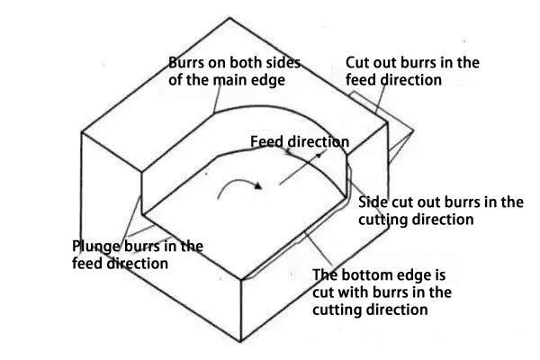
Burrs formed by end milling CNC machining
Generally speaking, compared with other burrs, the burrs in the cutting direction of the bottom edge are large in size and difficult to remove. Therefore, this paper takes the burr in the cutting direction from the bottom edge as the main research object to carry out research. According to the different size and shape of the burr in the cutting direction in the end milling, it can be divided into the following three types: I-type burr (larger size, difficult to remove, and high removal cost), II-type burr (smaller size small, can be removed or removed easily) and type III burrs i.e. negative burrs.
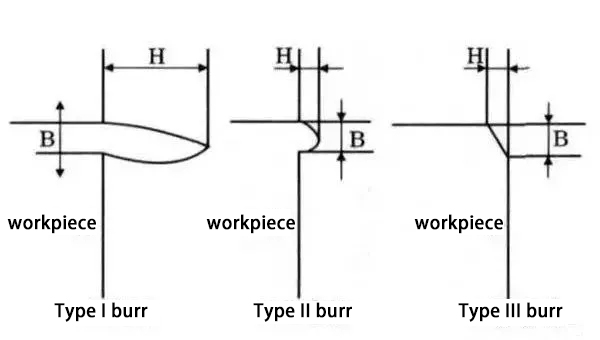
Types of burrs in the cutting direction when the bottom edge is cut during CNC milling
2. The main factors affecting the formation of end milling burrs
The formation of burrs is a very complex material deformation process. Various factors, such as workpiece material properties, geometry, surface treatment, tool geometry, tool cutting path, tool wear, cutting parameters, and coolant usage, all directly affect burr formation.
Figure 3 is a block diagram of the influencing factors of end milling burrs. Under specific CNC milling conditions, the shape and size of end milling burrs depend on the combined effect of various influencing factors, but different factors have different effects on the formation of burrs.
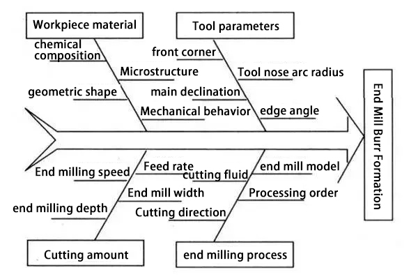
CNC Milling Burr Forms Causal Control Chart
01. Tool entry/exit
Under normal circumstances, the burr generated when the tool is rotated out of the workpiece is larger than the burr generated when the tool is rotated into the workpiece.
02. Plane cut out corner
The plane cutting angle has a great influence on the formation of burrs in the cutting direction of the bottom edge. The plane cutting angle is defined as when the cutting edge is rotated out of the workpiece end face, in the plane perpendicular to the axis of the milling cutter at a point on the cutting edge, the direction of the cutting speed (the vector combination of the tool speed and the feed speed) at this point is the same as that of the cutting edge. The angle between the workpiece end face directions. The direction of the workpiece end face is from the tool screw-in point to the tool screw-out point. As shown in Figure 5, Ψ is the plane cut-out angle, and its range is 0°<Ψ≤180°.
The test results show that the burr height changes with the change of cutting depth, that is, the burr changes from I-type burr to II-type burr with the increase of cutting depth. The minimum milling depth that produces Type II burrs is usually referred to as the limit depth of cut, expressed by dcr. Figure 6 shows the effect of plane cutout angle and depth of cut on burr height when machining an aluminum alloy.
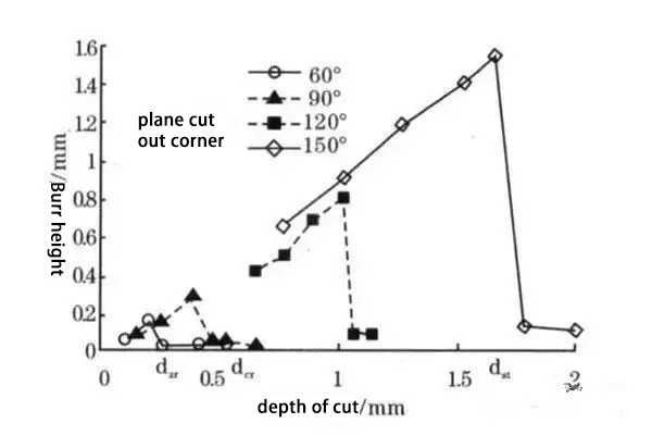
Burr form and plane cut-out angle and depth of cut
It can be seen from Figure 6 that the larger the plane cut-out angle, the greater the limit cutting depth; when the plane cut-out angle is greater than 120°, the size of the I-type burr is larger, and the limit cutting depth of the transition to the II-type burr is also larger. Therefore, a small plane cut-out angle is conducive to the generation of type II burrs, because the smaller the Ψ, the higher the support stiffness of the terminal surface, and the more difficult it is for the burrs to form.
It can be seen from Figure 5 that the size and direction of the feed speed will have a certain influence on the size and direction of the composite speed v, which will then affect the plane cut-out angle and burr formation. Therefore, the larger the offset angle α between the feed speed and the exit edge, the smaller the Ψ, which is more conducive to suppressing the formation of large burrs (as shown in Figure 7).
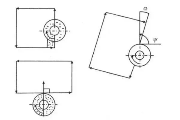
Influence of feed direction on burr formation
03. Tool tip exit sequence EOS
During end milling, the burr size is largely determined by the exit sequence of the tool tip. As shown in Figure 8: Point A is the point on the secondary cutting edge, point C is the point on the main cutting edge, and point B is the apex of the tool tip. It is assumed that the tool nose is sharp, that is, the radius of the tool nose arc is not considered. If the B-C side exits the workpiece first, and the A-B side exits the workpiece later, the chips are hinged on the machined surface, and as the milling progresses, the chips are pushed out of the workpiece, forming a larger size bottom edge and cutting out burrs in the cutting direction. If the A-B side exits the workpiece first, and the B-C side exits the workpiece later, the chip is hinged on the transition surface and is cut out of the workpiece, forming a smaller size bottom edge to cut out the cutting direction burr.
The test shows that: ①The exit sequence of the tool tip that increases the size of the burr in turn is:
ABC/BAC/ACB/BCA/CAB/CBA. ②The result produced by EOS is the same, except that under the same exit sequence, the size of the burr produced by the plastic material is larger than that of the brittle material.
The exit order of the tool tip is not only related to the geometry of the tool, but also to factors such as the feed rate, milling depth, workpiece geometry and cutting conditions.
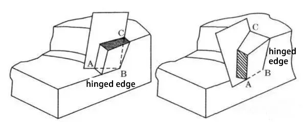
Figure 8 Tool tip withdrawal sequence and burr formation
04. The influence of other factors
①CNC milling parameters, CNC milling temperature, cutting environment, etc. will also have a certain impact on the formation of burrs. Some main factors such as feed speed, CNC milling depth, etc. are reflected by the plane cutting angle theory and the tool nose exit sequence EOS theory come out, this will not go into details;
②The better the plasticity of CNC machining parts, the easier it is to form I-type burrs. In the CNC machining process of end-milling brittle materials, if the feed rate or plane cutting angle is large, it is conducive to the formation of type III burrs (deficiencies);
③ When the angle between the end surface of the workpiece and the machined plane is greater than a right angle, the formation of burrs can be suppressed due to the increased support rigidity of the end surface;
④The use of milling fluid is beneficial to prolong the life of the tool, reduce the wear of the tool, lubricate the CNC milling process, and then reduce the size of the burr;
⑤ Tool wear has a great influence on the formation of burrs. When the tool wears to a certain extent, the arc of the tool tip increases, not only the size of the burr in the exit direction of the tool, but also the formation of burr in the cutting direction of the tool, the mechanism needs to be further Research in depth.
⑥ Other factors such as tool material also have a certain influence on the formation of burrs. Under the same cutting conditions, diamond tools are more conducive to inhibiting burr formation than other tools.
3. The basic way to control the formation of CNC milling burr
The formation of end milling burrs is affected by many factors, which are not only related to the specific CNC milling process, but also related to the workpiece structure, tool geometry and other factors. To reduce end milling burrs, it is necessary to control and reduce the generation of burrs from many aspects.
01. Reasonable structural design
The formation of burrs is largely affected by the structure of CNC machined parts. The structure of CNC machined parts is different, and the shape and size of burrs at the edges after CNC machining are also very different. If the material and surface treatment of CNC machined parts are predetermined, then the workpiece geometry and edges are an important factor in determining the formation of burrs.
02. Proper CNC machining sequence
The CNC machining sequence also has a certain influence on the shape and size of the end milling burr. Different burr shapes and sizes have different deburring workloads and related costs. Therefore, selecting an appropriate CNC machining sequence is an effective way to reduce deburring costs. Figure 10 shows the use of proper CNC machining sequences to control the generation of larger burrs.
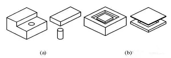
Figure 9 Select CNC machining sequence control method
In Figure 10a, if the hole is drilled first and then the plane is milled, a large cut-out milling burr is likely to be generated on the circumference of the hole; if the plane is milled first and then the hole is drilled, there will be only a small cut-in burr on the hole circumference. Similarly, in Fig. 10b, the size of the burr formed by CNC milling the upper surface and then milling the concave contour is smaller than the size of the burr formed by CNC machining the concave contour first and then milling the plane.
03. Avoid tool exit
Avoiding tool withdrawal is an effective way to avoid burr formation, because tool withdrawal is the main factor for burr formation in the cutting direction. Under normal circumstances, the burr generated by the milling cutter when it is rotated out of the workpiece is larger, and the burr generated when it is rotated into the workpiece is smaller. Therefore, the milling cutter should be avoided as far as possible during the CNC machining process. As shown in Figure 4, the burrs generated using Figure 4b are smaller than those generated in Figure 4a.
04. Select the appropriate tool path
It can be seen from the previous analysis that when the plane cut-out angle is less than a certain value, the size of the burr produced is small. The plane cut-out angle can be changed by changing the milling width, feed rate (magnitude and direction) and rotation speed (magnitude and direction). Therefore, the generation of type I burrs can be avoided by choosing the appropriate tool path (see Figure 11).
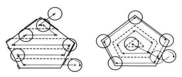
Figure 10 Controlling the tool path method
Fig. 10a shows a traditional zigzag cutting path, and the shaded part in the figure represents the part where large burrs may be produced in the cutting direction. Figure 10b uses an improved toolpath, which avoids the generation of cutting burrs. Although the tool pass in Figure 11b is slightly longer than the one in Figure 10a and takes a little more CNC milling time, since no additional deburring process is required, the use of Figure 10a requires a lot of deburring time (although shaded in the figure). The part where the burr is generated is not many, but all the edges where the burr is must be completed during actual deburring), so in general, in terms of burr control, the cutting route shown in Figure 10b is better than the route shown in Figure 10a .
05. Select appropriate CNC milling parameters
End milling parameters (such as feed per tooth, end milling width, end milling depth, and tool geometry angle, etc.) have a certain influence on the formation of burrs.
The formation of end milling burr is affected by many factors, among which the main influencing factors are: tool exit/entry, plane cutting angle, tool nose exit sequence, milling parameters, etc. The final shape and size of the burr is the result of a combination of factors.
Starting from the structural design of CNC machined parts, the arrangement of processing technology, the amount of CNC milling and the selection of tools, this paper analyzes the main influencing factors of CNC milling burrs, and proposes a method to control the milling cutter route and select the appropriate CNC machining sequence. The technologies, processes and methods for suppressing or reducing milling burrs, such as the method and the structural design improvement method, provide a feasible technical solution for actively controlling the size of the burr, improving the quality of CNC machined parts, reducing costs and shortening the production cycle in CNC milling.

These are the insights of VMT CNC machining manufacturers. If you have a better way, you can contact us to discuss with us.

 +86 15099911516


 Read more