16 years one-stop China custom CNC machining parts factory

Hey there I’m VMT Sam!
With 25 years of CNC machining experience we are committed to helping clients overcome 10000 complex part-processing challenges all to contribute to a better life through intelligent manufacturing. Contact us now
 301 |
Published by VMT at Aug 20 2026 | Reading Time:About 4 minutes
301 |
Published by VMT at Aug 20 2026 | Reading Time:About 4 minutes


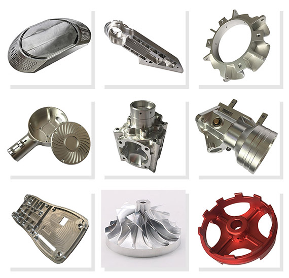
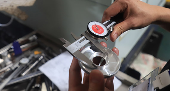
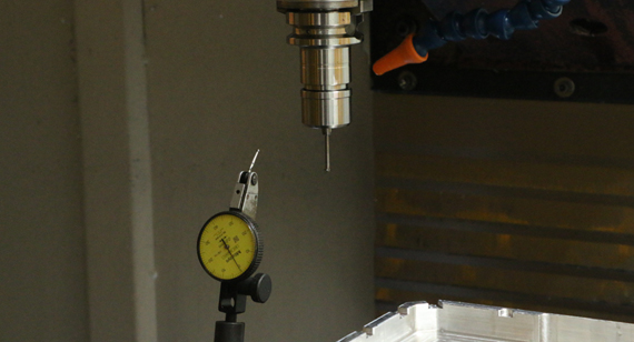
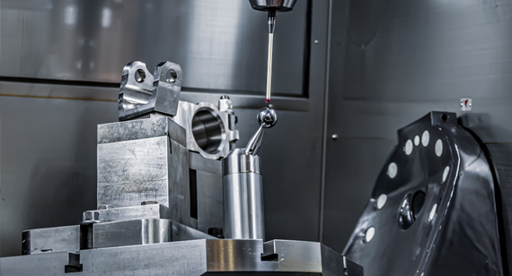
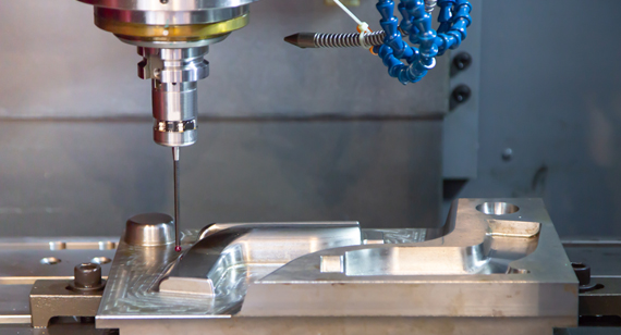
Tolerance in manufacturing is the acceptable differential range for your team to determine the size based on the form, fit and function of the CNC part. While tight tolerances ensure superior dimensional consistency and product quality (at a higher manufacturing cost), overly loose dimensional tolerances can result in assembly failures. Similarly, loose geometric tolerances (such as concentricity errors) can degrade the image performance of precision optical devices. Understanding how CNC machining tolerances affect cost, choice of manufacturing process, inspection options and materials can help you better determine product designs and CNC machining production plans.
What we VMT CNC Machining Factory can achieve is ±0.005mm to ±0.01mm for common metals and ±0.02mm to ±0.5mm for plastics. At the end of blog, we will also share how we helped a client to optimize tolerance and cost for their custom shafts.
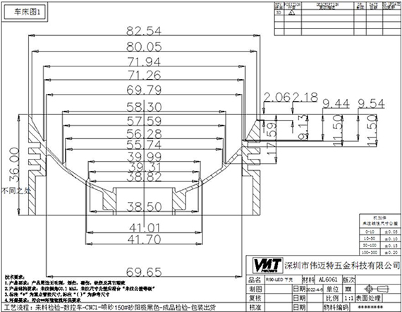
It is important to remember that tighter machining tolerances are more costly due to increased scrap, additional fixtures, special measuring tools and/or longer cycle times, as machines may need to be slowed down to maintain tighter tolerances(high tolerance machining/ close tolerance machining). Depending on the tolerance callout and the geometry associated with it, the cost can be more than double that of maintaining standard tolerances.
Global geometric tolerances can also be applied to CNC part drawings. Depending on the geometric tolerance and the type of tolerance applied, additional costs may be incurred due to increased inspection time.
The best way to apply cnc tolerances, when design criteria need to be met to minimize cost, is to apply tight or geometric tolerances only to critical areas.
Table: tolerances vs CNC machining costs
To optimize both functionality and budget, you will need to understand how manufacturing complexity scales with cnc tolerance tightness. The table below illustrates the cost, processing, and inspection trade-offs across different tolerance tiers:
| Tolerance Level | Typical Range (mm / inch) | Relative Cost Multiplier | Cycle Time & Scrap Impact | Suitable Areas |
| Standard machining tolerances | ±0.100 mm (±0.004″) |
1.0x (Baseline) |
Standard cutting speeds; minimal scrap risk | Non-critical contours, clearance holes, chamfers, external aesthetics |
| Precision (Tight) | ±0.020 mm to ±0.010 mm (±0.0008″ to ±0.0004″) |
1.5x – 2.5x | Reduced feed rates; higher tool wear; ~1–3% scrap rate | Bearing seats, press-fit pins, mating surfaces, threaded holes |
| Ultra-Precision | ±0.005 mm (±0.0002″) |
3.0x – 5.0x+ | Multi-pass finishing; thermal expansion control required; ~3–5% scrap risk | Precision optical lens mounts, high-speed spindle bores, hydraulic valve spools |
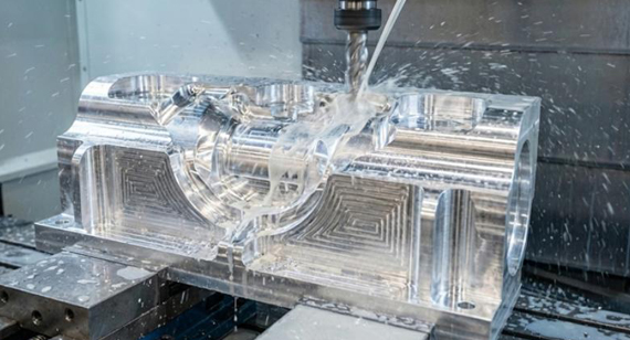
Specifying tighter tolerances than standard tolerances can actually change the optimum manufacturing process for a CNC part. For example, a hole that can be made on an end mill within one tolerance may need to be drilled or even ground on a lathe within tighter tolerances, adding to setup costs and lead times. Below table shows more examples about main cnc features and tolerance and manufacturing changes:
Table: Impact of Tolerance Selection on CNC Manufacturing Processes
| Feature Type | Standard Tolerance (±0.05 mm) | Tight Tolerance (±0.01 mm) | Ultra-Precision Tolerance (±0.005 mm) | Stage 1 Impact (Standard → Tight) | Stage 2 Impact (Tight → Ultra-Precision) |
| Hole / Bore | Direct drilling or end mill interpolation on 3-axis VMC | Pre-drilling + H7 precision reaming / fine boring head | Rough drilling + Stress-relief heat treatment + ID Grinding / Wire EDM | Adds 1 finishing pass; cycle time increases by 15%–25% | Requires secondary clamping & off-line grinding/EDM; per-hole cost increases by 150%–300% |
| Flatness & Surface | High-speed face milling in a single pass | Multi-pass fine face milling with reduced feed rates | Rough milling + Stress-relief annealing + Precision surface grinding , or Lapping | Requires lower feed rates to guarantee roughness; machining time increases by 20% | Introduces heat treatment & grinder routing; extends lead time by 2–3 days; doubles cost |
| OD Shafts | Direct turning on a standard 2-axis CNC lathe | Multi-pass fine turning with high-precision carbide inserts | Swiss-type CNC lathe with guide bushing + secondary Centerless OD Grinding | Requires premium inserts & slower feed rates; tool and labor costs increase by 15%–30% | Requires Swiss lathe & centerless grinding; setup costs increase by 40%–60% |
| Slots & Cavities | Direct slotting with standard end mills | Rigid end mills + precision collets with multi-pass corner clearing | Rough milling + Precision EDM, or Micro milling with ultra-fine tooling | Requires high-precision tool holders & reduced depth of cut; machining time increases by 30% | Requires electrode fabrication or micro-milling; electrode & processing costs increase by 100%–200% |
| Threads & Tapped Holes | Standard tapping or thread milling | Tapping + 100% inspection with precision thread gauges | Special tool pre-machining + Thread gauge fitting / Thread grinding machine | Requires 100% full inspection; inspection time increases by 50% | Conventional tapping fails; requires thread grinding or EDM; unit price increases by over 200% |
Remember, when adding a tolerance to a part, you should consider how the feature will be inspected. If a feature is difficult to machine, it is likely also difficult to measure. Certain functions require specialized inspection equipment, which can increase CNC part cost.
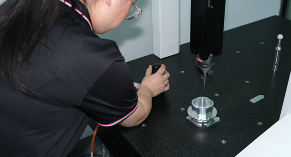
Table: Inspection equipment vs machining tolerance
| Inspection Equipment | Features & Tolerance Types Measured | Target Tolerance Level | Note |
| Coordinate Measuring Machine (CMM) | Complex 3D geometries, critical hole locations, GD&T (True Position, Concentricity, Parallelism, Perpendicularity) | Down to ±0.001 mm (±0.00004″) | Requires offline programming, specialized probe setups, and stabilization in a 20°C climate-controlled lab. |
| Optical Comparator & Vision Systems | Delicate 2D profiles, micro-holes, thread forms, thin-walled features, external radii | Down to ±0.005 mm (±0.0002″) | Provides non-contact measurement, preventing surface distortion or scratching on soft metals and engineered plastics. |
| Air Gauges (Pneumatic Gauging) | Internal cylinder bores, hole roundness, taper, precision bearing seats | Down to ±0.001 mm (±0.00004″) | Delivers instant, high-repeatability readings without contact damage to ground or honed internal bore surfaces. |
| Granite Surface Plate & Height Gauge | Step heights, total thickness, surface Flatness, Parallelism | Down to ±0.005 mm (±0.0002″) | Enables fast shop-floor verification using calibrated indicator heads. |
| Pin Gauges, Thread Plugs & Micrometers | Go/No-Go limits for internal threads, pin holes, shaft outer diameters (OD) | ±0.01 mm to ±0.005 mm | Fast for spot-checking, but 100% manual inspection on high-volume production runs significantly raises labor costs. |
The difficulty of CNC machining a part to specific tolerances can be very material dependent. In general, the softer the material, the more difficult it is to maintain the specified tolerances due to the material bending as it is cut. Plastics such as nylon, HDPE, and PEEK may not hold the tight tolerances of steel or aluminum without special tooling considerations. Below table shows the common materials with CNC machining tolerances:
Table: Common materials with vs achievable CNC machining tolerances
| Material Category | Representative Grades | Common Tolerance | Precision Limit |
| Aluminum Alloys | 6061-T6, 7075-T6, 2024 | ±0.05 mm (±0.002″) | ±0.005 mm (±0.0002″) |
| Stainless Steel | 304, 316L, 17-4 PH | ±0.05 mm (±0.002″) | ±0.010 mm (±0.0004″) |
| Carbon & Alloy Steel | 1045, 4140, 8620 | ±0.05 mm (±0.002″) | ±0.008 mm (±0.0003″) |
| Tool Steel | D2, A2, H13, O1 | ±0.05 mm (pre-heat treat) | ±0.005 mm (post-grinding) |
| Brass & Copper Alloys | C360 Brass, C932 Bronze | ±0.05 mm (±0.002″) | ±0.005 mm (±0.0002″) |
| Titanium Alloys | Grade 5 (Ti-6Al-4V), Grade 2 | ±0.05 mm (±0.002″) | ±0.010 mm (±0.0004″) |
| Engineered Plastics | POM (Acetal/Delrin), PEEK | ±0.10 mm (±0.004″) | ±0.020 mm (±0.0008″) |
| Soft Plastics & Fluoropolymers | Nylon 6/6, PTFE (Teflon), HDPE | ±0.15 mm (±0.006″) | ±0.050 mm (±0.002″) |
The cnc part is rarely finished immediately after coming off the milling machine or lathe. Surface treatments and post-processing steps are critical for enhancing corrosion resistance, wear resistance, and visual appearance. However, some surface finishing process alters the final dimensions of a part by either adding a coating layer, removing surface material, or causing thermal deformation. The dimensional tolerance you may specify it is “as-machined” or “ after xxx surface treatment or xxx post-processing.
Design for Manufacturability (DFM) centers on a foundational principle in CNC machining: apply tight tolerances only where necessary, and keep them relaxed everywhere else.
Assigning uniform tight tolerances across an entire drawing unnecessarily increases machining time, accelerates tool wear( portion of cost) , and raises scrap rates. By categorizing part features into critical and non-critical zones, you can achieve the necessary functionality while reducing manufacturing costs:
Table: Functional Feature Allocation: Loose vs. Tight Tolerances
| Classification | Typical Application Features | Recommended Tolerance | DFM & Manufacturing Rationale | Cost & Production Impact |
| Non-Critical Zones (Loose Tolerances) |
• External non-mating contours • Chamfers & radius edges • Relief pockets & weight-reduction cutouts • Clearance holes & non-mating faces |
±0.10 mm to ±0.20 mm (±0.004″ to ±0.008″) |
Allows maximum cutting speeds and higher feed rates. | Baseline Cost (1.0x) Enables high-speed roughing, minimal setup time, and low scrap risk. |
| Critical Zones (Tight Tolerances) |
• Precision bearing seats & dowel pin holes • Concentricity alignment bores for optical barrels • High-pressure sealing surfaces & precision threads |
±0.005 mm to ±0.010 mm (±0.0002″ to ±0.0004″) |
Essential for ensuring precise assembly fits (interference/transition), maintaining optical axial alignment, and preventing fluid or pressure leaks in dynamic sealing systems. | 2.0x to 4.0x Cost Multiplier Requires finishing passes, precision tooling, slower feed rates, and CMM verification. |
The above is the knowledge about the tolerance of CNC parts, I hope it will be helpful to you.
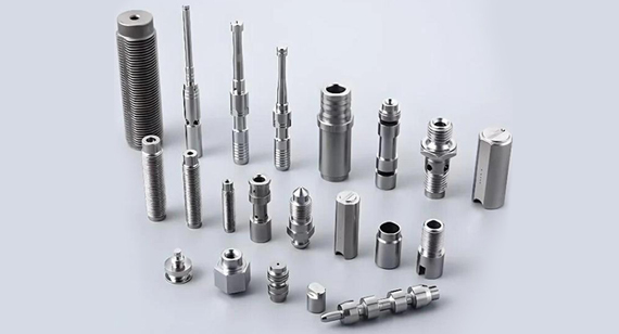
CNC Custom Shafts: DFM Tolerance and Cost Optimization for Automotive Transmission Shafts
An automotive industry client found us to produce 316L stainless steel transmission shafts (diameter 25 mm × 180 mm) for an electric vehicle powertrain system. The drawing specified tight tolerances (±0.008 mm) across all outer diameters, keyed slots, and step shoulders, along with a black oxide surface treatment.
The client's previous machining vendor provided an exorbitant unit price quote due to the complex routing required—including multi-pass turning, cylindrical grinding, EDM slotting, and post-plating dimensional adjustments. Seeking a cost-effective alternative, the client submitted the project to our team for DFM evaluation.
Our engineering team performed a detailed feature-by-feature function analysis. We identified that while the ±0.008 mm tolerance and 0.005 mm concentricity were strictly necessary for the main bearing journal seats and dynamic seal surfaces to prevent vibration and fluid leaks, the middle non-mating relief shaft and keyway depth could safely be relaxed to a standard ±0.05 mm without affecting mechanical performance. Furthermore, we recommended switching from Black Oxide to Electroless Nickel Plating (10 µm ± 2 µm), which provided superior corrosion resistance while allowing to precisely pre-machine raw dimensions.
By relaxing non-critical tolerances and optimizing the manufacturing routing, we reduced secondary grinding passes on 60% of the shaft's length and processed the parts on our multi-axis Swiss-type CNC lathes in a single setup. This optimized workflow reduced total production costs by 32% and shortened lead time from 30 days to 22 days. All finished shafts passed 100% CMM inspection for concentricity and thread limits, delivering a high-precision, cost-optimized solution successfully.
Mastering CNC part tolerances comes down to one core engineering practice: designing for precision where it matters, and efficiency everywhere else. As shown throughout this guide, specifying tight tolerances unnecessarily drives up cycle times, tooling wear, inspection labor, and post-processing complexity. By applying rigorous DFM principles: reserving ultra-precision tolerances (down to ±0.005 mm) strictly for critical mating or sealing features while maintaining standard tolerances (±0.05 mm to ±0.10 mm) elsewhere; then, you can reduce production expenses without sacrificing part quality or assembly fit. Looking for an experienced engineering team to optimize tolerance and cost for your CNC product designs? Welcome to contact us to ensure your components hit exact technical specifications within budget.[2D Drawings (PDF files), 3D Drawings (IGS/STP/STEP files)].
Send your 2D drawings, 3D CAD models, material requirements, dimensional tolerances, GD&T requirements, surface-finish requirements, prototype quantity and production quantity. VMT will review manufacturability, tolerance strategy, inspection and quotation requirements.
All information and uploaded files are secure and confidential.
1 Tell us what you need
2 Get solution & quote
3 Approve production
Email: inquiry@vimetal.com.cn
Can you provide quick turnaround for tight-tolerance prototype parts?
Yes. With our multi-axis CNC machines, in-house CMM inspection, and extensive raw material stock, we can deliver precision custom prototypes with tight tolerances (down to ±0.005mm) in as fast as 3-7 days.
What is a bilateral tolerance?
A bilateral tolerance specifies a variation allowed in both positive and negative directions from the nominal dimension (e.g., 20mm +0.02/-0.02mm).
What is a reasonable tolerance in inches for a machined part?
Standard machining tolerance for custom metal parts is typically around ±0.005″ (±0.127 mm). High-precision machining usually ranges between ±0.001″ to ±0.0002″ (±0.025 mm to ±0.005 mm) depending on feature complexity and budget. Aerospace machining tolerances is better to be ±0.005 mm or even smaller.
Is 0.1 mm a tight tolerance?
It depends on the material: For plastic parts (like PTFE or POM), 0.1 mm (±0.004″) is considered a fairly tight tolerance due to thermal expansion and flexibility. However, for precision metal parts, 0.1 mm is a standard or loose tolerance (tight tolerances for metals are typically ±0.01mm or tighter).
What are the four main types of tolerances in machining?
The four primary types are:
How do you calculate tolerance?
Tolerance is calculated as the difference between the maximum limit of size and the minimum limit of size: Tolerance = Upper Limit - Lower Limit
(Example: If a target shaft size is 19.00 mm with a maxlimit of 19.03 mm and a min limit of 18.97 mm, the total tolerance is 19.03 - 18.97 = 0.06 mm.)
The technical information and manufacturing advice shared on the VMT website are for general guidance only. While we strive for accuracy, VMT does not guarantee that the processes, tolerances, or material properties mentioned are applicable to every specific project. Any reliance you place on such information is strictly at your own risk. It is the buyer's responsibility to provide definitive engineering specifications for any production orders. Final specifications and service terms shall be subject to the formal contract or quotation confirmed by both parties.


 +86 15099911516




 Read more