15 years one-stop China custom CNC machining parts factory

Hey there I’m VMT Sam!
With 25 years of CNC machining experience we are committed to helping clients overcome 10000 complex part-processing challenges all to contribute to a better life through intelligent manufacturing. Contact us now
 222 |
Published by VMT at Oct 19 2021
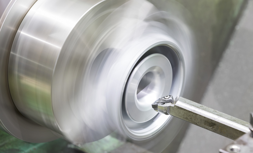
CNC lathe machining is one of the common machining methods. In order to process parts such as shaft parts, inner and outer cylindrical surfaces of disc parts, inner and outer conical surfaces of any cone angle, etc., the most widely used CNC machining is turning. And milling processing.
Due to the different contours of the parts processed by CNC turning, many CNC systems will be divided into "transverse turning", "longitudinal turning (also known as "reciprocating turning") and other processes. Let's follow us to learn about it!
Horizontal CNC machining turning
Features of horizontal CNC machining turning:
In horizontal CNC machining and turning, the moving direction of the turning tool is parallel to the axis of rotation of the custom machined part. If it is the main spindle, the moving direction of the tool is from right to left; if the machine is equipped with a sub-spindle, the moving direction of the tool is from the left To the right. Horizontal turning can be used to machine the outer circle and inner hole, but when processing the inner hole, you must first pre-drill a bottom hole. In addition to processing the outer circle, you can also process the end face.

Longitudinal turning, groove cutting
Longitudinal turning characteristics of side and end faces (also called reciprocating cutting):
When longitudinal CNC machining is performed on the side of a customized machined part, the feed direction of the slitting turning tool is perpendicular to the axis of rotation of the workpiece. In the longitudinal turning of the end face of the workpiece, the feed direction of the cutting tool is parallel to the workpiece axis. The slitting turning tool has three cutting edges, so that the material removal process in the radial and axial directions is as uninterrupted as possible. (Because the rapid movement stroke is minimized)
The shape of the blade and the shape of the knife body of the grooving knife and the slitting knife are different.
Grooving features of edge and end faces:
When grooving is cut only in the transverse feed direction, the machining process of side groove cutting is perpendicular to the direction of the axis of rotation. The machining process of face groove cutting is parallel to the direction of the axis of rotation, and the grooving tool can only withstand the force applied perpendicular to the direction of the tool axis. Groove cutting technology is mainly used to machine grooves, usually (not absolutely) the groove to be machined has the same width as the grooving tool.
The difference between horizontal CNC turning and longitudinal CNC turning
Horizontal CNC turning processing:
1. Large cross-feeding can be realized, that is, a large chip cross-sectional area.
2. It can achieve a larger transverse feed, that is, a larger chip cross-sectional area
3. High feed rate can be achieved during rough machining 4. Perfect chip discharge effect
5. Perfect chip discharge effect
6. Not all contours can be processed by horizontal CNC turning with limited tools, and more tools may need to be replaced during processing.
Horizontal CNC turning is generally used for streamlined contour structures with arc transitions.
Longitudinal CNC turning processing:
1. Large cross-feeding can be realized, that is, a large chip cross-sectional area.
2. It can achieve a larger transverse feed, that is, a larger chip cross-sectional area
3. High feed rate can be achieved during rough machining 4. Perfect chip discharge effect
4. Perfect chip discharge effect
5. Not all contours can be processed by horizontal CNC turning with limited tools, and more tools may need to be replaced during processing.
Longitudinal CNC turning is generally used for machining parts with deep grooves and 90° corner structures. These structures can only be processed by this process.
Ready To Start Your Next Project?
Get Instant Quote

Request a Free Quote
Send us a message if you have any questions or request a quote. We will get back to you ASAP!