16 years one-stop China custom CNC machining parts factory

Hey there I’m VMT Sam!
With 25 years of CNC machining experience we are committed to helping clients overcome 10000 complex part-processing challenges all to contribute to a better life through intelligent manufacturing. Contact us now
 532 |
Published by VMT at Jul 08 2026 | Reading Time:About 4 minutes
532 |
Published by VMT at Jul 08 2026 | Reading Time:About 4 minutes


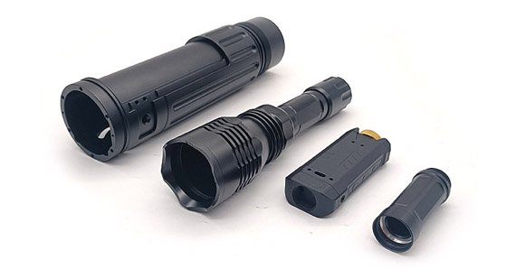
A flashlight shell looks like a simple tube and head assembly, but small machining errors can cause thread jamming, poor sealing, battery fit issues, heat dissipation problems, burrs, scratches, and unstable assembly. A controlled CNC machining process helps reduce these risks before they affect your final flashlight product.
CNC machining a flashlight shell usually includes drawing review, blank selection, CNC turning, CNC milling, thread machining, heat dissipation groove machining, O-ring groove machining, knurling, deburring, surface preparation, anodizing allowance control, final inspection, and protective packaging.
This guide focuses only on the CNC machining process for flashlight shells. If you want to understand materials, design risks, applications, and full project planning, you can also read the complete aluminum flashlight housing CNC machining guide.
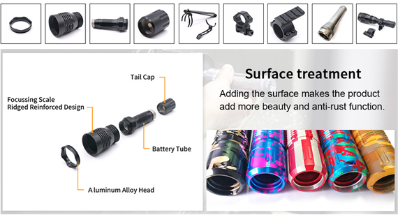
A flashlight shell is not only an outside cover. It is a functional structure that connects the LED module, reflector, lens, battery, driver board, tail cap, switch, O-ring, clip, and other parts. Before machining starts, the factory must understand which features are cosmetic surfaces and which features affect assembly, sealing, heat dissipation, or electrical contact.
Common flashlight shell features include:
Holds the LED module, reflector, lens, bezel, and heat dissipation structure.
Controls battery fit, internal diameter, wall thickness, and connection with the head and tail cap.
Includes thread connection, switch structure, spring seat, and sealing area.
Affect assembly smoothness, repeated opening and closing, and sealing performance.
Support waterproof or dustproof performance.
Help transfer heat away from high-power LED modules.
Improves hand feel and anti-slip performance.
Affect optical assembly and positioning accuracy.
Requires clean edges, accurate position, and burr control.
Supports branding, model numbers, serial numbers, and direction marks.
| Flashlight Shell Feature |
Machining Method |
Key Quality Point |
| Battery tube |
CNC turning, boring | ID, OD, roundness, wall thickness |
| Tail cap thread |
CNC turning, threading | Thread fit, burrs, smooth assembly |
| Flashlight head |
CNC milling, CNC turning | LED seat, heat grooves, surface finish |
| O-ring groove |
Grooving, precision turning | Groove width, depth, edge condition |
| Grip texture |
Knurling, milling, grooving | Uniform texture and comfortable hand feel |
| Lens seat |
Boring, milling, facing | Flatness, concentricity, assembly fit |
| Charging port |
CNC milling, drilling | Position, clean edge, no burrs |
| Heat fins |
CNC turning or milling | Groove depth, spacing, surface consistency |
Tip: Before machining, classify all features into functional surfaces, sealing surfaces, appearance surfaces, and non-critical surfaces. This helps avoid over-machining low-risk areas while keeping strict control on important dimensions.
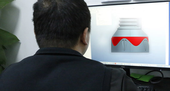
The first step is not cutting material. It is reviewing the drawing, 3D model, assembly structure, tolerance requirements, and surface finish notes. Many flashlight shell problems happen because machining starts before the supplier fully understands how the part will be assembled.
During the drawing review, VMT focuses on:
Flashlight head, battery tube, tail cap, lens area, switch hole, and connection method.
Internal diameter, external diameter, thread size, groove depth, lens seat, battery cavity, and assembly clearance.
Which dimensions require tight tolerance and which dimensions can use standard machining tolerance.
Thread type, pitch, depth, thread relief, lead-in chamfer, and post-anodizing fit.
O-ring groove width, groove depth, sealing surface roughness, and edge condition.
Anodizing, hard anodizing, sandblasting, polishing, brushing, or laser engraving.
Prototype, small batch, or mass production affects fixture design, machining sequence, and inspection planning.
| Drawing Review |
ItemWhy It Matters |
| Wall thickness | Reduces deformation risk during turning or clamping |
| Thread tolerance | Prevents loose fit, tight fit, or rough assembly |
| O-ring groove | Affects sealing and waterproof reliability |
| LED seat | Affects heat transfer and optical module fit |
| Surface finish | Affects machining allowance and cosmetic control |
| Batch quantity | Affects fixture, process planning, and cost control |
Note: If the drawing only gives a general shape but does not define thread fit, sealing groove tolerance, or surface finish requirements, VMT can provide DFM feedback before production. This helps reduce rework and sample rejection.
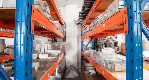
Blank selection affects material waste, machining time, cost, deformation risk, and final quality. For flashlight shells, the most common blank types include aluminum bar, aluminum tube, forged blank, and extrusion blank. The best choice depends on part size, structure, production volume, mechanical requirements, and appearance requirements.
Common blank options include:
Suitable for prototypes, small batches, solid flashlight heads, tail caps, and parts requiring more machining flexibility.
Suitable for battery tubes or hollow flashlight bodies where material removal needs to be reduced.
Suitable for parts requiring better strength, dense structure, or near-net shape before machining.
Suitable for long, consistent profiles or special tube-like structures when volume supports extrusion tooling.
Sometimes used for complex shapes, but it may require more control for porosity, surface quality, and machining stability.
| Blank Type |
Suitable Flashlight Part |
Advantage |
Point to Control |
| Aluminum bar |
Head, tail cap, prototype housing | Flexible and easy to source | More material removal |
| Aluminum tube |
Battery tube, long body shell | Reduces machining time and waste | Tube straightness and wall thickness |
| Forged blank |
High-strength head or body | Better strength and structure | Higher preparation cost |
| Extrusion blank |
Long or custom profile shell | Efficient for volume production | Tooling cost and profile tolerance |
| Casting blank |
Some complex rough shapes | Near-net shape possibility | Porosity and surface defects |
For many custom flashlight shell projects, 6061 aluminum bar or tube is a practical option because it is stable for CNC machining and suitable for anodizing. However, the blank should not be selected only by material price. A cheaper blank may increase machining time, deformation risk, or rejection rate.
Tip: If your flashlight shell has a long battery tube, using a suitable tube blank may reduce material waste. If your flashlight head has complex fins and internal features, bar stock may provide more machining flexibility for prototypes.
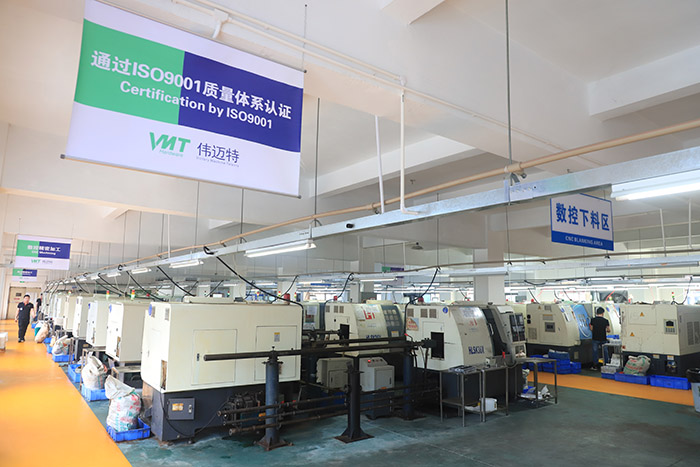
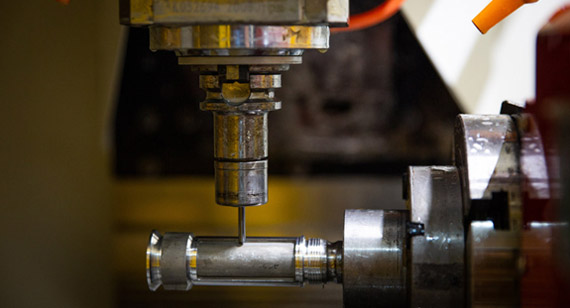
CNC turning is commonly used for round flashlight shell parts such as the battery tube, tail cap, bezel, lens ring, and threaded connections. These parts usually require accurate outside diameter, inside diameter, roundness, thread fit, and surface finish.
For battery tube machining, the main process may include:
For tail cap machining, the process may include:
| Turned Part |
Key Machining Focus |
Common Risk |
| Battery tube |
ID, OD, roundness, wall thickness | Deformation or poor battery fit |
| Tail cap |
Thread, switch seat, O-ring groove | Tight assembly or sealing issue |
| Bezel |
Lens seat, front thread, surface finish | Poor lens fit or visible tool marks |
| Lens ring |
Concentricity, flatness, thread | Optical assembly issue |
Battery tubes are often long and thin-walled, so clamping force must be controlled carefully. If the part is clamped too tightly, it may deform. If it is clamped too loosely, vibration may affect surface finish and dimensional stability.
Note: For thin-wall flashlight tubes, rough turning and finish turning should be planned carefully. Leaving a suitable allowance for finishing helps improve final dimensional accuracy and surface quality.
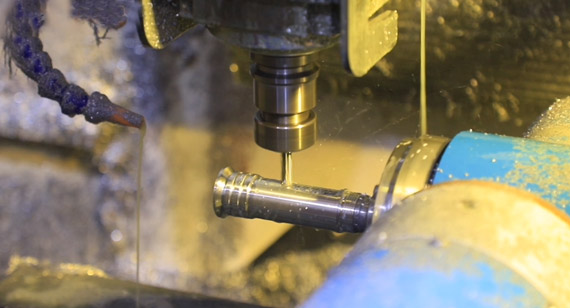
The flashlight head often has more complex features than the battery tube. It may include heat dissipation grooves, side holes, switch openings, charging ports, flat mounting surfaces, anti-roll flats, lens seats, LED module pockets, and decorative details. These features often require CNC milling after turning.
CNC milling can be used to machine:
For simple round flashlight heads, CNC turning may complete most features. For flashlight heads with side openings, complex grooves, or non-round geometry, CNC milling is needed. In some cases, 4-axis or 5-axis CNC machining can reduce repeated clamping and improve feature accuracy.
| Milling Feature |
Why It Matters |
| Side switch hole | Affects switch assembly and user operation |
| Charging port | Requires accurate position and clean edges |
| Clip slot | Supports accessory assembly |
| Anti-roll flat | Improves user handling and product function |
| LED module pocket | Affects heat transfer and internal fit |
| Mounting hole | Affects bracket or accessory installation |
Tip: Repeated clamping can create positioning error. For complex flashlight heads, fixture design and machining sequence are important for controlling hole position, appearance surfaces, and assembly alignment.
High-power LED flashlights need good heat control. The flashlight shell, especially the head area, often acts as part of the heat dissipation path. CNC machined heat dissipation grooves or fins increase surface area and help transfer heat away from the LED module.
Heat dissipation features may include:
When machining heat grooves, the main quality points include:
| Heat Groove Risk |
Possible Result |
VMT Control Method |
| Groove too deep |
Weak structure or deformation | Review wall thickness and cutting depth |
| Fin too thin |
Burrs, bending, or damage | Optimize toolpath and cutting parameters |
| Uneven spacing |
Poor appearance | Use stable programming and inspection |
| Rough surface |
Lower appearance quality | Control tools and finishing process |
| Burrs between fins |
Poor hand feel and finishing defects | Add controlled deburring |
Heat dissipation grooves are functional and cosmetic at the same time. If they are uneven, rough, or full of burrs, the part may still function but fail appearance inspection. For premium flashlight shells, machining consistency matters.
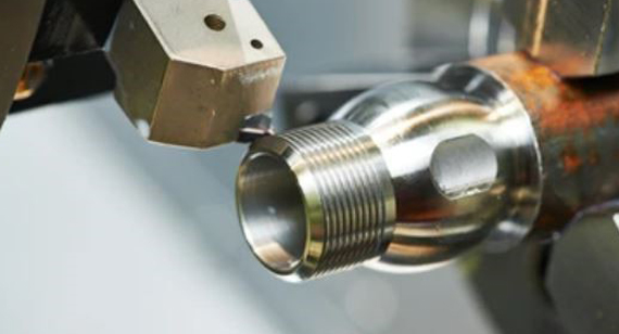
Thread machining is one of the most important processes in flashlight shell manufacturing. The flashlight head, battery tube, tail cap, lens ring, and bezel often rely on internal and external threads for assembly. Poor thread quality can directly cause customer complaints.
Common thread problems include:
To control thread quality, VMT focuses on:
| Thread Location |
Function |
Quality Requirement |
| Head-to-body thread | Connects head and battery tube | Smooth fit and alignment |
| Tail cap thread | Allows repeated opening and closing | Durable and burr-free |
| Lens ring thread | Holds lens and reflector | Accurate fit and clean surface |
| Bezel thread | Protects lens and front structure | Smooth assembly and appearance |
| Internal accessory thread | Supports modules or inserts | Stable size and depth |
Note: Anodizing adds surface thickness. For tight flashlight threads, machining size should consider post-anodizing fit. Otherwise, threads that fit well before anodizing may become too tight after finishing.
Many flashlight shells require O-ring grooves to improve waterproof or dustproof performance. These grooves are small, but they have a big impact on product reliability. If the groove is too shallow, the O-ring may be compressed too much. If it is too deep, sealing pressure may be insufficient. If the edge is too sharp, the O-ring may be damaged during assembly.
O-ring groove machining should control:
| O-Ring Groove Problem |
Possible Risk |
| Groove too shallow | O-ring over-compression and assembly difficulty |
| Groove too deep | Weak sealing pressure |
| Sharp edge | O-ring cutting or damage |
| Burrs in groove | Sealing failure or difficult assembly |
| Rough sealing surface | Leakage risk |
| Poor groove position | Misalignment with mating part |
At VMT, O-ring grooves and sealing surfaces are treated as functional features, not simple decorative grooves. We review the groove design, tool selection, machining method, and inspection plan before production.
Tip: If your flashlight shell is designed for waterproof or outdoor use, provide the O-ring size and sealing requirement during quotation. This helps the machining team review whether the groove design is practical.
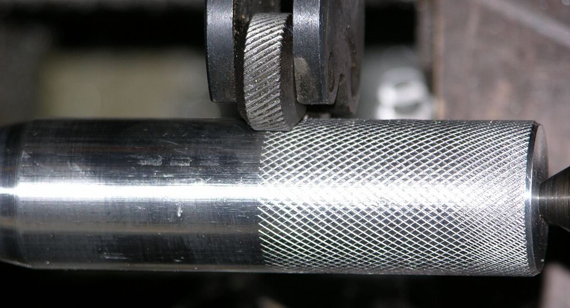
Grip texture improves user comfort and anti-slip performance. It also affects product appearance and brand positioning. For outdoor flashlights, tactical flashlights, and EDC flashlights, the grip area is one of the most important user-touch surfaces.
Common grip features include:
| Grip Texture Type | Benefit | Point to Control |
| Diamond knurling | Strong anti-slip feel | Uniform depth and clean edges |
| Straight knurling | Simple and functional grip | Pattern consistency |
| Circular grooves | Easy to machine and clean appearance | Groove spacing and burrs |
| Milled texture | Custom brand appearance | Toolpath and edge quality |
| Decorative grip pattern | Premium product identity | Surface consistency |
Grip texture machining must balance function and comfort. If the texture is too sharp, it may feel uncomfortable. If it is too shallow, it may not provide enough grip. If the pattern is uneven, the finished flashlight may look low quality.
Note: Surface finishing can change the final feel of the texture. Sandblasting, anodizing, or hard anodizing may slightly affect sharpness, color, and hand feel, so grip texture should be evaluated together with the finishing process.
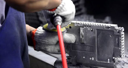
Deburring is often underestimated, but it is critical for flashlight shells. A flashlight housing has many threads, grooves, holes, fins, and grip textures. Burrs can affect assembly, sealing, appearance, hand feel, and surface finishing quality.
Common burr locations include:
| Burr Location |
Possible Problem |
| Thread area | Rough assembly or cross-threading |
| O-ring groove | Sealing failure or O-ring damage |
| Charging port | Poor component fit or sharp edge |
| Switch hole | Assembly difficulty or user discomfort |
| Heat fins | Poor appearance and hand feel |
| Internal cavity | Battery scratching or contamination |
| Lens seat | Optical assembly issue |
VMT uses controlled deburring, chamfering, edge breaking, and inspection to reduce these risks. For cosmetic flashlight housings, deburring must be consistent. Over-deburring can damage appearance or change dimensions, while under-deburring can create assembly and safety problems.
Tip: Clearly define critical edges on the drawing if you need a specific chamfer size or edge break requirement. This helps avoid inconsistent hand deburring during batch production.
Most aluminum flashlight shells are anodized or hard anodized after machining. Surface preparation before anodizing affects final appearance, color consistency, thread fit, and corrosion resistance. A good machined part can still fail if surface preparation is not controlled.
Before anodizing, VMT checks:
Common surface preparation methods include:
| Finishing Requirement | Machining Preparation |
| Black anodizing | Clean surface, stable roughness, no deep scratches |
| Hard anodizing | Allowance control for tight threads and grooves |
| Sandblasting + anodizing | Uniform surface and controlled blasting texture |
| Polishing | Lower tool marks and controlled cosmetic surfaces |
| Laser engraving | Proper marking area and stable anodized layer |
Anodizing allowance is especially important for threads, grooves, sliding fits, and sealing areas. If coating thickness is not considered, the final part may be too tight or difficult to assemble.
Note: For flashlight housings with tight threads, the machining and anodizing teams should confirm whether the thread fit needs compensation before surface finishing.

Final inspection confirms whether the flashlight shell meets drawing, assembly, surface, and packaging requirements before shipment. For flashlight shells, inspection should include both dimensional and cosmetic checks.
VMT final inspection may include:
| Inspection Item |
Purpose |
| ID and OD | Ensures battery fit and external assembly |
| Thread gauge | Confirms thread size and fit |
| Assembly test | Checks real part connection |
| O-ring groove | Supports sealing reliability |
| Hole position | Ensures switch or charging port fit |
| Surface appearance | Reduces cosmetic rejection |
| Burr inspection | Improves hand feel and assembly |
| Packaging check | Reduces shipping scratches and dents |
Packaging is also part of quality control. Aluminum flashlight shells with anodized finishes can be scratched during transportation if packaging is not protected properly. VMT uses suitable separation, wrapping, trays, foam, cartons, or customized packaging methods according to part shape, finish, and shipment quantity.
Tip: For black anodized or cosmetic flashlight housings, request protective packaging that separates parts from each other. This helps reduce friction marks during international shipping.
Flashlight shell machining requires stable control from drawing review to final packaging. The problems below are common in real production, especially when the part includes thin walls, deep cavities, threads, sealing grooves, and anodized surfaces.
| Common Problem |
Possible Cause |
VMT Solution |
| Battery tube deformation |
Thin wall, high clamping force, aggressive cutting | Optimize fixture, reduce clamping stress, control machining sequence |
| Rough thread assembly |
Burrs, tool wear, wrong allowance, poor thread relief | Review thread design, use proper tools, inspect with thread gauges |
| O-ring sealing risk |
Incorrect groove size, burrs, rough sealing surface | Control groove width/depth, edge break, and sealing surface finish |
| Visible tool marks |
Poor toolpath, worn tools, unstable cutting | Optimize cutter, toolpath, speed, feed, and finishing pass |
| Heat fin burrs |
Thin groove structure and difficult deburring | Use stable machining parameters and controlled deburring |
| Anodizing color difference |
Surface inconsistency, mixed material batch, poor pretreatment | Control material batch, surface preparation, and finishing coordination |
| Tight fit after anodizing |
Coating thickness not considered | Review anodizing allowance before machining |
| Scratches during shipping |
Poor packaging or part-to-part contact | Use protective separation, wrapping, and suitable cartons |
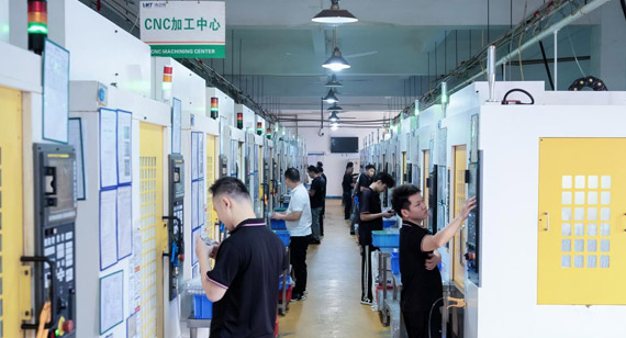
A reliable CNC machining process does not depend on one step only. It depends on engineering review, material control, fixture design, machining sequence, toolpath optimization, in-process inspection, surface finishing coordination, final inspection, and packaging protection.
CNC machining a flashlight shell is not only about cutting an aluminum tube. It requires proper drawing review, blank selection, CNC turning, CNC milling, thread control, sealing groove machining, grip texture machining, deburring, anodizing preparation, inspection, and packaging.
VMT supports custom CNC machined flashlight shells from prototype to batch production. If your flashlight project needs accurate threads, stable sealing grooves, smooth battery fit, clean heat dissipation fins, premium anodized appearance, and reliable inspection, upload your 2D drawings or 3D files for a quote and DFM review.
Send your drawings, requirements, and target quantity. VMT will review your project and provide a machining solution and quote.
1 Tell us what you need
2 Get solution & quote
3 Approve production
Email: inquiry@vimetal.com.cn
1. What is the best CNC process for machining a flashlight shell?
Most flashlight shells require a combination of CNC turning and CNC milling. CNC turning is used for round features such as battery tubes, tail caps, threads, and lens rings. CNC milling is used for side holes, switch openings, charging ports, clip slots, anti-roll flats, and complex head features.
2. Why is CNC turning important for flashlight battery tubes?
Battery tubes are usually round and require accurate internal diameter, external diameter, wall thickness, roundness, and thread fit. CNC turning helps control these features efficiently. For long or thin-wall tubes, clamping force and machining sequence must be controlled to reduce deformation.
3. How do you control internal and external threads on flashlight shells?
VMT reviews thread size, pitch, relief design, tool selection, burr control, and anodizing allowance before machining. During production, thread gauges and assembly checks help confirm smooth fit. For anodized flashlight shells, post-finishing thread fit should also be considered.
4. How do you machine O-ring grooves for waterproof flashlight shells?
O-ring grooves are machined by precision turning or grooving tools. The key points include groove width, depth, edge condition, surface roughness, and burr control. If the flashlight requires waterproof performance, the O-ring size and sealing requirements should be reviewed during DFM.
5. How do you reduce deformation in thin-wall flashlight tubes?
Deformation can be reduced by optimizing wall thickness, clamping method, fixture support, cutting depth, toolpath, roughing and finishing sequence, and inspection points. For thin-wall parts, aggressive cutting and excessive clamping should be avoided.
6. Can VMT machine heat dissipation fins on flashlight heads?
Yes. VMT can machine heat dissipation fins, circular grooves, stepped profiles, and other cooling features on aluminum flashlight heads. The process must control groove depth, fin thickness, burrs, surface quality, and appearance consistency.
7. Can knurling be added to a CNC machined flashlight shell?
Yes. Knurling or custom grip texture can be added to improve hand feel and anti-slip performance. The texture depth, pattern consistency, edge sharpness, and surface finishing effect should be reviewed before production.
8. Why should anodizing allowance be considered before machining?
Anodizing creates a surface layer that can affect tight threads, grooves, and assembly fits. If the allowance is not considered, the part may assemble smoothly before anodizing but become too tight after finishing. This is especially important for flashlight threads and mating surfaces.
9. What inspections are needed for CNC machined flashlight shells?
Common inspections include ID, OD, thread fit, O-ring groove size, hole position, lens seat, battery cavity, surface roughness, anodizing appearance, burrs, scratches, and assembly fit. For high-precision or batch production parts, inspection reports can be provided according to customer requirements.
10. What files should I send for a flashlight shell machining quote?
You can send 2D drawings, 3D CAD files, STEP files, PDF drawings, samples, photos, material requirements, surface finish requirements, tolerance notes, and production quantity. If you are not sure whether your design is easy to machine, VMT can review your files and provide DFM feedback before quoting.


 +86 15099911516




 Read more