16 years one-stop China custom CNC machining parts factory

Hey there I’m VMT Sam!
With 25 years of CNC machining experience we are committed to helping clients overcome 10000 complex part-processing challenges all to contribute to a better life through intelligent manufacturing. Contact us now
 808 |
Published by VMT at Oct 08 2024
808 |
Published by VMT at Oct 08 2024


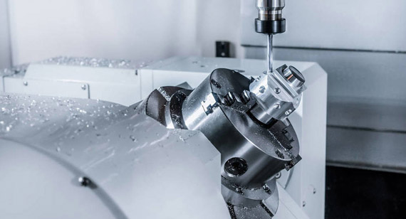
In CNC machining and precision engineering, achieving the correct fit between two parts is critical for ensuring the reliability, performance, and longevity of assemblies. Two commonly used fitting methods are press fit and slip fit, each offering different characteristics in terms of force required for assembly, the degree of tightness between mating parts, and their respective applications. These fits are essential in areas like machinery, automotive components, and aerospace parts where high precision is necessary for both fixed and movable parts.
Understanding the differences between press fit and slip fit is crucial when choosing the right method for a specific application. This article will explore both techniques, providing a clear comparison of their respective manufacturing processes, as well as the specific applications and challenges associated with each fit.
A press fit (also called an interference fit) refers to a method of joining two parts by forcefully inserting one component into another, creating friction that holds the parts together. In a press fit, the component being inserted (often referred to as the pin or shaft) is slightly larger than the receiving part (such as a hole or bushing). The result is a tight, secure fit with significant resistance to movement.
This method is commonly used in applications where mechanical strength and stability are required without the use of fasteners, adhesives, or welding. Press fits are typically applied in CNC machined parts such as gears, bearings, shafts, and bushings.

A typical example of a press fit is the assembly of a bearing into a housing. The outer diameter of the bearing is manufactured slightly larger than the inner diameter of the housing. During assembly, force is applied to press the bearing into place. The interference between the two components creates enough friction to hold the bearing securely in place without additional fasteners.
This technique is widely used in industries like automotive, aerospace, and heavy machinery where components must endure high loads and rotational stresses without becoming loose.
The press fit force required for assembly is determined by several factors, including the size of the parts, the material properties, and the amount of interference (the difference between the part's diameters). To calculate the press fit force, you must understand two key forces:
1. Pressure at the Mating Interface
The pressure exerted between the two components at the interface is a function of the interference and the modulus of elasticity of the materials. A tighter fit will generate more pressure at the interface, which increases the holding force but also raises the assembly force required.
2. Axial Retention Force
The axial retention force is the force that keeps the inserted component from slipping out of the assembly. This force is determined by the amount of interference and the friction coefficient between the two surfaces. Materials with higher friction coefficients, such as steel or aluminum, will provide better axial retention than smoother materials like plastics.
There are two main techniques for achieving a press fit: applying force and utilizing thermal expansion and contraction. Both methods are widely used in custom CNC machining and CNC prototype machining for creating interference fits.
1. Force
The most straightforward way to achieve a press fit is through mechanical force. A hydraulic press or a hammer is typically used to push one part into another. For precision CNC machined components, hydraulic presses are often favored because they can provide consistent force without damaging the part.
2. Thermal Expansion/Contraction
Another common method for achieving a press fit is through thermal expansion of the outer part or contraction of the inner part. The outer component is heated to expand its diameter, or the inner component is cooled (often using liquid nitrogen) to shrink its size. Once the parts reach room temperature, the tight fit is achieved as the materials return to their normal dimensions.
A slip fit, also known as a clearance fit, allows two parts to move freely relative to each other while still maintaining close proximity. Unlike a press fit, where the parts are tightly bonded, a slip fit has a slight clearance between the components. This clearance enables smooth movement without significant resistance, making slip fits ideal for parts that need to move or rotate with minimal friction.
Slip fits are used in applications where parts must align precisely but still be able to move independently, such as bearings on a shaft, guide rails, or sliding mechanisms in mechanical systems.

Different Types of Slip Fits
Slip fits can vary based on the amount of clearance between the parts and their intended application. Below are the common types of slip fits:
1. Running Fit
A running fit provides the most clearance between the parts, allowing for free movement with minimal friction. This type of fit is used in parts like shafts and bearings that need to rotate or slip with ease.
2. Easy Slip
An easy slip fit offers more control than a running fit but still allows for smooth, friction-free movement. It is often used in assemblies requiring frequent adjustment or manual alignment.
3. Loose Fit
A loose fit allows for more play between the parts, making it suitable for components that need to accommodate minor misalignments or thermal expansion. It is typically used in non-critical applications.
4. Slip Fit
A standard slip fit has a controlled clearance, offering some movement but with a tighter fit than a running fit. This is commonly used in applications where minimal movement and close tolerances are required.
5. Position Clearance Fit
A position clearance fit offers very minimal clearance, allowing precise positioning while still providing the ability to slip. It is commonly used in CNC machining services where parts must be aligned accurately but still require the flexibility to move during operation.
An example of a slip fit is the guide rail system in linear motion components, such as those used in CNC machines. In this case, the guide rails are fitted with slight clearance to allow smooth movement while maintaining precision alignment. This system allows the machine to move parts with high accuracy, which is essential for processes like cutting, milling, and drilling.
Achieving a slip fit involves controlling the clearance between the two components. This can be done through careful machining or manual adjustment during assembly.
1. Force
In some cases, a slight amount of force may be used to achieve a slip fit. The parts are aligned and pushed together with minimal resistance, allowing for smooth movement once assembled.
2. Manual
Slip fits are often achieved manually by inserting one part into another and ensuring the clearance is just right for the required movement. This technique is frequently used in precision assemblies where tolerances are critical.
While both press fit and slip fit involve mating two components, they have several key differences that make them suitable for different applications.、

1. Interference/Clearance
Press Fit: There is interference between the two parts, meaning one part is slightly larger than the other, resulting in a tight, friction-based connection.
Slip Fit: There is clearance between the two parts, allowing for easy movement or sliding.
2. Degrees of Freedom
Press Fit: The parts are locked together and have no relative movement once assembled.
Slip Fit: The parts can move relative to each other, enabling rotational or sliding motion.
3. Mechanical Deformation
Press Fit: The insertion process may cause slight mechanical deformation to both parts, enhancing the frictional bond.
Slip Fit: No deformation occurs during assembly, as the clearance prevents excessive force.
4. Assembly and Disassembly
Press Fit: Assembly typically requires significant force, and disassembly can be difficult or impossible without damaging the parts.
Slip Fit: Assembly and disassembly are easier and can often be done manually or with minimal force.
5. Manufacturability
Press Fit: Requires very tight tolerances in machining, increasing manufacturing complexity and cost.
Slip Fit: Easier to manufacture due to the looser tolerances, which can reduce costs.
6. Application
Press Fit: Ideal for permanent assemblies where high strength and stability are required.
Slip Fit: Used for moving parts or assemblies that require flexibility and precision.
| Criteria |
Press Fit |
Clearance |
| Interference/Clearance |
Interference |
Clearance |
| Movement |
No movement after assembly |
Allows relative movement |
| Assembly |
Requires force (mechanical or thermal) |
Manual or light force assembly |
| Mechanical Deformation |
Possible during assembly |
None |
| Applications |
Permanent, high-strength joints |
Moving parts (e.g., bearings, shafts) |
| Ease of Disassembly |
Difficult, may damage parts |
Easy, minimal damage |
| Manufacturing Tolerances |
Tighter tolerances needed |
Looser tolerances acceptable |
Understanding the differences between press fit and slip fit is critical for engineers, designers, and manufacturers involved in CNC machining. Press fits are ideal for permanent assemblies requiring strength and stability, while slip fits are suitable for applications where parts need to move freely but still maintain precise alignment.
Both methods have specific manufacturing requirements, with press fits demanding tighter tolerances and greater assembly forces, while slip fits offer more flexibility with easier assembly and disassembly. Knowing which fit is appropriate for your project will ensure that your CNC machining parts perform optimally and meet the intended design specifications.
What criteria are used to determine press fit and slip fit size?
Press fit and slip fit sizes are determined by the amount of interference or clearance between the parts, material properties, and the desired function of the assembly.
Is a transition fit considered a slip fit?
A transition fit can be considered a type of slip fit, as it allows for minimal movement, often used in assemblies requiring a balance between clearance and interference.
What is the difference between a slip fit and a transition fit?
A slip fit has more clearance, allowing free movement, while a transition fit has tighter tolerances and offers a slight interference that may still allow limited movement.
Why are press fits so expensive?
Press fits are often more expensive due to the tighter tolerances required during machining and the specialized equipment needed for assembly.
What are the three types of fits?
The three main types of fits are interference fit (press fit), transition fit, and clearance fit (slip fit).
What is a slip fit bearing?
A slip fit bearing is a type of bearing that fits with clearance around a shaft, allowing smooth rotational movement with minimal friction.
What is the difference between a press fit bushing and a slip fit bushing?
A press fit bushing is installed by force, creating a tight, immovable connection, while a slip fit bushing has clearance, allowing movement between the bushing and the shaft.
What is the press fit tolerance for steel?
Press fit tolerances for steel typically range between 0.001 to 0.005 inches (25 to 125 microns), depending on the application and material properties.

 +86 15099911516


 Read more