15 years one-stop China custom CNC machining parts factory

Hey there I’m VMT Sam!
With 25 years of CNC machining experience we are committed to helping clients overcome 10000 complex part-processing challenges all to contribute to a better life through intelligent manufacturing. Contact us now
 4246 |
Published by VMT at Oct 07 2024
4246 |
Published by VMT at Oct 07 2024


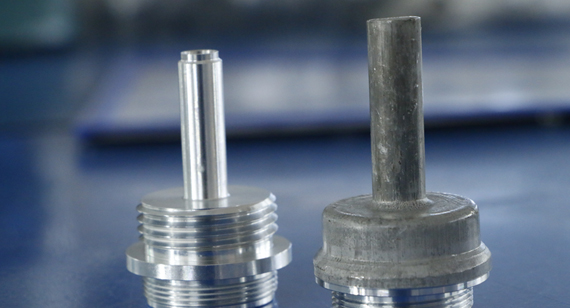
In CNC precision machining, surface roughness plays a crucial role in determining the quality, performance, and durability of machined parts. Surface roughness refers to the small deviations in the texture of a machined surface. These deviations, while often imperceptible to the naked eye, can significantly affect the part’s functionality, lifespan, and aesthetic appeal.
Achieving the right surface roughness is not just about aesthetics but also about ensuring that parts meet technical and functional requirements. This guide will explore the concept of surface roughness, its importance in CNC machining services, how it is measured, and the factors affecting it. We’ll also cover the various types of surface finishes and provide tips on how to choose the right surface roughness for your project.
Surface roughness is a measure of the texture of a machined surface, characterized by the vertical deviations of the surface profile from its ideal form. It’s a critical aspect of CNC machining parts as it affects friction, wear resistance, sealing performance, and the overall appearance of the part.
Surface roughness is typically quantified using several standardized parameters, with Ra (average roughness) being the most common. Surface roughness can range from smooth, mirror-like finishes to coarse textures, depending on the requirements of the project. Achieving the desired surface roughness involves controlling various factors such as machining processes, cutting tools, and material properties.

Surface finish is measured and defined using several key parameters, each providing different insights into the surface texture. Common parameters include:
Ra (Average Roughness): Represents the arithmetic average of the absolute deviations of the surface profile from the mean line.
Rz (Maximum Height of Profile): The average of the largest peak-to-valley heights over a defined sampling length.
RMS (Root Mean Square): Similar to Ra but emphasizes larger deviations more, making it suitable for analyzing surfaces with significant variations.
These parameters help manufacturers standardize and communicate the quality of the surface finish, ensuring parts meet technical specifications across various industries.
Surface roughness has far-reaching implications in engineering and manufacturing, particularly in industries that require precise fits, high-performance components, and resistance to environmental factors like corrosion and wear. A poorly machined surface can lead to reduced part life, increased friction, and operational inefficiencies.
1. Surface Anomalies Can Become Nucleation Points for Cracks or Corrosion
A rough surface with excessive peaks and valleys can act as a breeding ground for stress concentrations, leading to premature failure. For example, cracks can initiate at these points under cyclic loading, potentially causing parts to fracture. Additionally, rough surfaces can trap contaminants or moisture, accelerating corrosion.
2. Engineers Need to Maintain Surface Control
In CNC prototype machining and production, controlling surface roughness ensures that parts function as intended, whether in terms of sealing, fitting, or friction reduction. Maintaining a consistent surface finish is essential for reducing maintenance needs, improving performance, and increasing the reliability of the part.
3. Surface Treatment Can Optimize Surface Electrical Conduction and Improve Conductivity
In electrical components, surface finish plays a critical role in optimizing conductivity. Smoother surfaces reduce contact resistance, improving the performance of electrical connections and ensuring that heat is efficiently dissipated.
Several factors influence surface roughness during the CNC machining process. Understanding these factors allows manufacturers to control and optimize the final surface finish based on the specific requirements of the project.
1. Temperature
Temperature fluctuations during machining can cause the material to expand or contract, which affects the surface texture. Excessive heat generated during cutting can lead to surface deformation or create an uneven finish. Cooling strategies, such as the use of lubricants or coolants, are often employed to mitigate these effects.
2. Cutting Technology
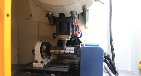
The type of cutting technology used—whether milling, turning, drilling, or grinding—greatly impacts the surface roughness. For instance, CNC machining parts produced through high-speed milling tend to have a smoother surface compared to parts that are manually milled.
3. Material Removal Rate and Feed Rate
The material removal rate and feed rate affect how aggressively the cutting tool interacts with the workpiece. Faster feed rates tend to produce rougher surfaces, while slower feed rates allow for finer cuts and smoother finishes. Balancing these rates is critical to achieving the desired roughness without compromising efficiency.
4. Cutting Tools
The geometry, sharpness, and material of the cutting tool significantly influence the surface roughness. Dull tools can create excessive heat and surface irregularities, while sharp tools provide smoother finishes. Additionally, the tool’s material—whether carbide, diamond, or high-speed steel—affects the finish quality.
5. Cutting Depth and Cutting Rate
The depth of cut and cutting speed are also important. Shallow cuts with controlled speeds yield finer finishes, while deeper cuts tend to produce rougher surfaces. Adjusting the cutting rate to suit the material type and tool geometry is necessary for optimizing surface roughness.
Surface roughness can be measured using various methods, depending on the required accuracy and the type of surface being analyzed. Accurate measurement is essential to ensure the part meets the desired specifications and performs as expected.
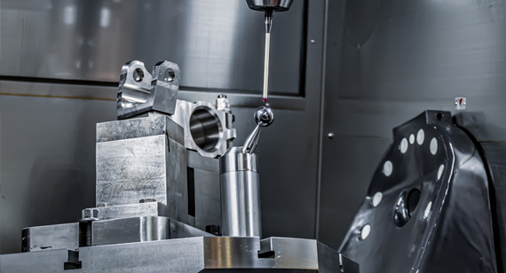
1. Direct Methods
Direct methods involve physically measuring the surface with a stylus that moves across the surface and records the vertical deviations. This method is highly accurate and widely used for CNC machining parts that require precise control over surface roughness.
2. Comparison Techniques
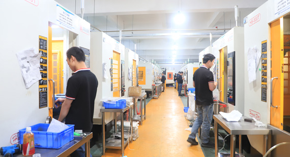
Comparison methods involve comparing the machined surface with standard surface finish charts or roughness specimens. This technique is less precise than direct methods but can be useful for quick, on-the-spot assessments in a CNC machining factory.
3. Non-contact Methods
Non-contact methods use sound or light waves, such as lasers or ultrasonic technology, to measure the surface roughness without physically touching the surface. These techniques are ideal for delicate parts that could be damaged by a stylus.
4. Online Measurement
Online surface roughness measurement systems are integrated into the machining process, allowing for real-time feedback and adjustments. This ensures consistent surface quality throughout production.
Several types of equipment are available for measuring and detecting surface finish. Each type offers different advantages based on the level of precision required and the nature of the material being measured.
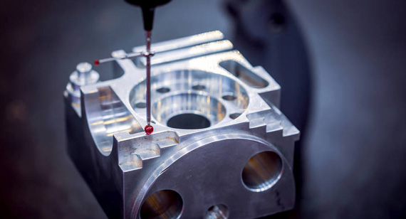
1. Profiling Techniques
Profilometers, including contact and non-contact varieties, are widely used for profiling surface roughness. These devices provide a detailed representation of the surface profile by measuring the peaks and valleys.
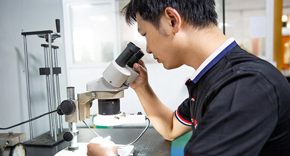
2. Microscopy Techniques
High-resolution microscopes can be used to visualize surface roughness at a microscopic level. Scanning electron microscopy (SEM) or atomic force microscopy (AFM) allows for extreme precision when analyzing very fine surfaces.

3. Area Techniques
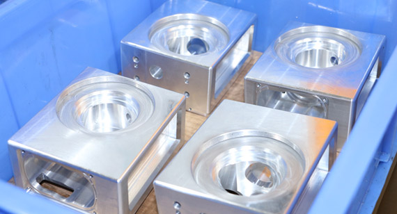
Area-based techniques, such as interferometry, measure surface roughness across a large area, providing a more comprehensive understanding of the surface texture. These techniques are useful for analyzing custom CNC machining parts with complex geometries.
4. Contact Profilometers
Contact profilometers use a stylus that moves across the surface, recording the vertical displacement to calculate surface roughness. These devices are highly accurate and are the standard for many industries requiring precise measurements.
5. Portable Surface Roughness Testers
Portable surface roughness testers are handheld devices that can be used in the field or on the production floor to quickly assess surface finish quality. These devices provide real-time feedback, allowing operators to make immediate adjustments.
Surface roughness is often expressed using standardized symbols, such as Ra, Rz, and RMS. Understanding these symbols is essential for interpreting technical drawings and ensuring that machined parts meet the required specifications.
1. Ra (Average Surface Roughness)
Ra is the most common parameter used to describe surface roughness. It represents the arithmetic mean of the absolute deviations of the surface profile from the mean line over a specified length.
2. Rmax (Vertical Distance from Peak to Valley)
Rmax is the maximum distance between the highest peak and the deepest valley on the surface profile. It provides insight into the extremes of surface irregularities.
3. Rz (Maximum Average Height of Profile)
Rz measures the average of the five highest peaks and five lowest valleys over the sampling length. It’s used in conjunction with Ra for a more detailed analysis of surface roughness.
4. Centerline Average (CLA)
CLA is similar to Ra but is based on the deviations from the centerline, providing an alternative measure of surface texture.
5. Rp (Distance between the Highest Peak of Profile and the Average Line within the Evaluation Length)
Rp measures the distance from the highest peak to the average line, giving insight into the prominence of surface peaks.
6. RMS (Root Mean Square Average of the Profile Height Variation from the Average Line)
RMS takes into account both positive and negative deviations from the mean line and squares them, emphasizing larger deviations. It’s useful for surfaces with significant variation.
7. Ra vs. RMS
While Ra and RMS are often used interchangeably, RMS tends to place more emphasis on larger deviations, making it more suitable for parts with a rougher surface.
Surface roughness can be expressed in various units and scales, such as Ra, RMS, and Rz. A surface roughness conversion chart helps manufacturers and engineers convert between these different scales, ensuring consistency across processes and industries.
| Roughness Grade Numbers |
American System |
Metric System |
||
| Ra(µin) |
RMS(µin) |
Ra(µm) |
RMS(µm) |
|
| N12 |
2000 |
2200 |
50 |
55 |
| N11 |
1000 |
1100 |
25 |
27.5 |
| N10 |
500 |
550 |
12.5 | 13.75 |
| N9 |
250 | 275 |
8.3 |
9.13 |
| N8 |
125 |
137.5 |
3.2 |
3.52 |
| N7 |
63 |
69.3 |
1.6 |
1.76 |
| N6 |
32 |
35.2 |
0.8 |
0.88 |
| N5 |
16 |
17.6 |
0.4 |
0.44 |
| N4 |
8 |
8.8 |
0.2 |
0.22 |
| N3 |
4 |
4.4 |
0.1 |
0.11 |
| N2 |
2 | 2.2 |
0.05 |
0.055 |
| N1 |
1 | 1.1 |
0.025 |
0.035 |
Choosing the right surface roughness for CNC machining services depends on the specific requirements of the project, including functionality, durability, and aesthetic preferences.
3.2 μm Ra: Suitable for most general-purpose parts that don’t require a highly polished finish.
1.6 μm Ra: Used for more precise parts where a smoother surface is needed, such as sealing components.
0.8 μm Radius: Appropriate for high-precision parts requiring a very smooth finish.
0.4 μm: Ideal for optical or aesthetic parts that demand mirror-like finishes.
Standard surface finishes in machining vary depending on the industry and application. Common finishes include Ra 3.2 μm for general-purpose machining and Ra 0.8 μm for high-precision parts. The standard is often specified in the project’s technical drawings.
Various surface finishes can be achieved through CNC machining, depending on the requirements of the part and the final application. These include:
1. Surface Finish After Machining
The basic finish achieved directly from the machining process, without additional treatments, typically has visible tool marks and may require further refinement.
2. Smooth Surface
A smooth surface is achieved through techniques like fine grinding or polishing, resulting in minimal roughness and a high-quality appearance.
3. Textured Finish
Textured finishes are created intentionally for specific aesthetic or functional purposes. This may include patterns, grooves, or rough textures.
4. Mirror Polish
Mirror polishing involves buffing the surface to achieve a highly reflective finish. It is commonly used for decorative parts or those requiring minimal friction.

5. Anodizing
Anodizing involves applying an oxide layer to the surface of aluminum parts to increase corrosion resistance and enhance appearance. Anodized finishes are available in various colors and textures.
Surface roughness is a critical aspect of CNC precision machining, affecting both the functionality and aesthetics of the final product. By understanding how surface roughness is measured, what factors influence it, and how to achieve the desired finish, manufacturers can ensure that their CNC machining parts meet industry standards and project requirements.
At VMT, we offer comprehensive CNC machining services, including expert guidance on surface roughness and finishing techniques to ensure the highest quality for your custom components.

What is the Unit of Ra?
Ra is measured in micrometers (μm) or microinches, depending on the industry standards.
What is 125 Surface Finish?
A 125 surface finish refers to an Ra value of 125 microinches, which is suitable for general-purpose parts.
How is Ra Related to Surface Smoothness?
Ra indicates the average roughness of a surface; the lower the Ra value, the smoother the surface.
What Does RMS 63 Mean?
RMS 63 refers to a roughness value of 63 microinches, commonly used for machined parts requiring moderate smoothness.
What is 0.8 um Surface Finish?
A 0.8 μm surface finish is a smooth, high-quality finish often used for precision components like seals and bearings.
What is RA and RZ in Surface Roughness?
Ra measures the average roughness, while Rz measures the average height difference between the highest peaks and the lowest valleys over a surface.
What is the Difference Between RA and SA?
Ra refers to average surface roughness, while Sa is the average height deviation over a surface area.
How to Convert RA to RZ?
Typically, Rz is approximately 4 to 7 times the Ra value, depending on the specific surface profile.
How to Check Surface Finish?
Surface finish can be checked using profilometers, roughness testers, or visual comparison techniques.
What is the Thickness UM?
UM refers to microns (μm), a unit of measurement used to define the thickness or surface roughness of materials.

 +86 15099911516


 Read more