16 years one-stop China custom CNC machining parts factory

Hey there I’m VMT Sam!
With 25 years of CNC machining experience we are committed to helping clients overcome 10000 complex part-processing challenges all to contribute to a better life through intelligent manufacturing. Contact us now
 949 |
Published by VMT at Aug 21 2024
949 |
Published by VMT at Aug 21 2024


In engineering design and manufacturing, selecting the appropriate fit is crucial to ensuring precise assembly, stable operation, and prolonged equipment life. A fit refers to the relationship between two or more parts (such as a hole and a shaft) when assembled, impacting the product's performance, reliability, and cost. This article will explore different types of fits, including interference fit, clearance fit, and transition fit, and how to achieve these fits precisely in CNC machined parts, providing guidance on choosing the right fit for your project.
An engineering fit refers to the specific relationship between two contacting mechanical parts (like a shaft and a hole) during assembly. This relationship dictates the relative position, movement characteristics, and load-bearing capacity of the parts. The choice of fit directly affects assembly efficiency, operational stability, and maintenance costs. Therefore, accurately selecting and defining the fit during the design phase is crucial.
In mechanical engineering, the hole and shaft are the most fundamental fit units. The hole is a circular through-hole or blind hole in a part designed to receive a shaft or other cylindrical components. The fit between the hole and shaft is achieved by defining their dimensional and geometrical tolerances, which determine the nature and precision of the fit.
A fit refers to the degree of tightness or looseness between a hole and a shaft when assembled, while tolerance is the allowable deviation from the nominal dimension of a part. The type of fit (such as interference, clearance, or transition) and the choice of tolerance zones jointly determine the assembly characteristics and performance of the parts. By precisely controlling tolerances, the desired fit can be achieved after assembly.
In mechanical engineering, fit types are typically named based on the positional relationship of the tolerance zones of the hole and shaft. ISO standards define various fit types and their codes, such as H7/g6, indicating that the hole uses the H7 tolerance zone and the shaft uses the g6 tolerance zone, forming a clearance fit. Designers can easily select and designate the required fit type by consulting relevant standards.
1. Interference Fit
An interference fit occurs when the actual size of the shaft is larger than the actual size of the hole, causing the shaft to elastically or plastically deform when inserted into the hole. This fit type provides high connection strength and positioning accuracy but is more difficult to assemble and requires higher material quality.
Subcategories of Interference Fit:
Press Fit: The shaft is pressed into the hole by force, creating a tight contact. Common in applications requiring high load-bearing capacity and resistance to vibration.
Drive Fit: Special structures on the shaft (e.g., threads, keyways) drive the hole's components to rotate or move. Often used in transmission devices.
Force Assembly: In some special cases, such as high-temperature environments or when materials do not allow plastic deformation, methods like freezing the hole or heating the shaft are used to achieve forced assembly.
2. Clearance Fit
A clearance fit occurs when the actual size of the shaft is smaller than the actual size of the hole, leaving a gap between the two parts. This fit type is easy to assemble, allows relative movement between parts, but offers lower connection strength and positioning accuracy.
Summary of Clearance Fit Types:
Loose Running: Provides significant clearance, allowing parts to rotate or slide freely, suitable for applications without positioning requirements.
Free Running: Moderate clearance, allowing smooth rotation or sliding between parts, commonly used in bearings and sliding guides.
Close Running: Minimal clearance, maintaining some rotational or sliding ability, suitable for applications requiring moderate precision.
Sliding: Designed specifically for sliding contact, such as in sliding bearings.
Location: Although a clearance fit, it achieves positioning through other means, such as keyways or dowel pins.
3. Transition Fit
A transition fit occurs when the tolerance zones of the hole and shaft partially overlap, potentially resulting in either a clearance or an interference fit depending on the actual assembly dimensions. This fit type offers greater flexibility and adaptability, with assembly precision and connection strength falling between those of clearance and interference fits.
Common Types of Transition Fit:
Similar Fit: The tolerance zones of the hole and shaft largely overlap, potentially resulting in a slight clearance or interference after assembly, suitable for applications requiring high but not overly stringent precision.
Fixed Fit: Although considered a transition fit, it often involves other methods (like fasteners or adhesives) to achieve a fixed connection, enhancing connection strength and stability.
When discussing "general engineering standards for fits," it's important to clarify the specific meaning of "fit" in different contexts. In the field of reliability engineering, especially in contexts related to FIT (Failures In Time), this term is used to measure the failure rate of individual components. However, in a broader engineering standard or general engineering context, "fit" does not directly refer to a specific type of engineering standard but appears as a unit of measurement.
Nonetheless, we can explore general engineering standards or principles related to "fit" from several perspectives:
Reliability Engineering Standards
In reliability engineering, FIT is a key metric for assessing the reliability of a component or system. Although FIT itself is not a standard, it is an integral part of reliability evaluation. General engineering standards may include requirements for reliability assessments, which may involve the use of FIT. These standards typically specify how reliability testing should be conducted, how failure rates should be calculated, and how reliability should be evaluated based on failure rates.
Standardized Testing Methods
To ensure that products from different manufacturers or different batches are comparable in reliability, standardized testing methods are often used to assess their FIT values. These testing methods may include running equipment under specific conditions and recording failures, then calculating the FIT value based on the test results. The adoption of standardized testing methods helps ensure the consistency and accuracy of evaluation results.
Quality Control and Assurance
Quality control and assurance are essential components of general engineering standards. For products or systems involving FIT evaluation, the standards may require manufacturers to implement stringent quality control measures to ensure that products reach the intended reliability level during production. These measures may include material inspection, process monitoring, product testing, and analysis of after-sales failure data.
Data Recording and Analysis
Accurate evaluation of a product or system's FIT value requires extensive operational data collection and detailed analysis. General engineering standards may require manufacturers to establish comprehensive data recording systems to continuously monitor and improve product reliability. Additionally, the standards may specify how collected data should be analyzed and processed to derive accurate reliability assessments.
Industry Standards and Norms
Specific industries may have FIT evaluation standards and norms tailored to their characteristics. These standards and norms may cover reliability assessment requirements, testing methods, data processing approaches, and quality control measures common to that industry. Adhering to these industry standards and norms is crucial to ensuring that a product or system meets industry-recognized levels of reliability.
In summary, "general engineering standards for fits" is not a direct concept. However, we can explore general engineering principles and requirements related to FIT from perspectives such as reliability engineering, standardized testing methods, quality control and assurance, data recording and analysis, and industry standards and norms. These principles and requirements help ensure that products or systems achieve the intended level of reliability during design and production, meeting user needs and expectations.
| Type of Fit |
Hole Basis |
Shaft Basis |
Fit Type |
Applications |
| Clearance Fit |
H11/c11 |
C11/h11 |
Loose Running Fit |
Pivots, parts with corrosion and dust, parts exposed to thermal changes |
|
H9/d9 |
D9/h9 |
Free Running Fit |
Cylinder-piston assemblies, slow-rotating parts |
|
| H8/f7 |
F8/h7 |
Close Running Fit |
Machine tool spindles, shaft bearings, sliding joints |
|
| H7/g6 |
G7/h6 |
Sliding Fit |
Sliding gears, clutch disks, hydraulic pistons |
|
| H7/h6 |
H7/h6 |
Locational Clearance Fit |
Machine tool guides, roller guide rails |
|
| Transition Fit |
H7/k6 |
K7/h6 |
Locational Transition Fit |
Wheels, brake disks, gears/pulleys on shafts |
| H7/n6 |
N7/h6 |
Locational Transition Fit |
Motor armature windings, gears |
|
| Interference Fit |
H7/p6 |
P7/h6 |
Locational Interference Fit |
Hubs, clutches, bushings for bearings |
| H7/s6 |
S7/h6 |
Medium Drive Fit |
Permanent gear/pulley assemblies, bearing mounting |
|
| H7/u6 |
U7/h6 | Force Fit |
Flange mounting, gears, shafts |
Achieving dimensional tolerances for fits in CNC machining parts relies on high-precision machining techniques and strict quality control. Manufacturers can utilize various methods to ensure part dimensions meet design specifications.
Techniques manufacturers can utilize include:
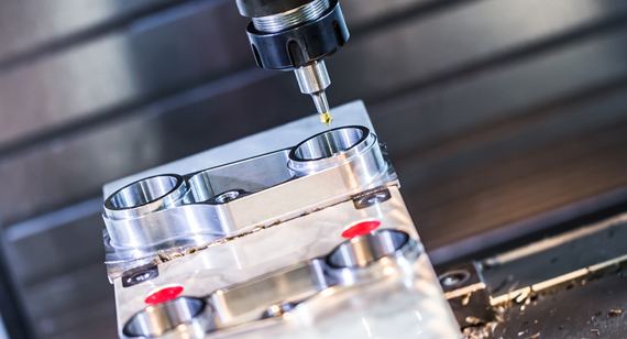
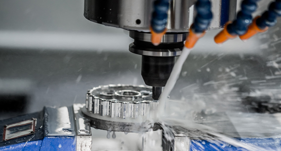
CNC Precision Machining: Using Computer Numerical Control (CNC) machines for precise machining ensures that the dimensions and shapes of parts reach micron-level accuracy. CNC machines offer high flexibility and automation, allowing them to accurately control tool paths according to pre-set programs, enabling high-precision machining of complex parts.
Grinding: For parts requiring higher surface finish and dimensional accuracy, grinding is a common method. By using a grinding wheel or other abrasive tools to remove material from the part's surface, dimensional tolerances can be further reduced, and surface quality improved.
Reaming: Reaming is a specialized process used to machine high-precision holes. A reamer is used to fine-tune pre-drilled holes, eliminating roundness errors and surface roughness, thereby enhancing the fit accuracy between holes and shafts.
Heat Treatment: Some materials may undergo dimensional changes due to stress relief or phase transformation during processing. Heat treatment (such as quenching or tempering) can stabilize material dimensions and properties, ensuring that fit accuracy is maintained.
Coordinate Measuring: After machining, using a Coordinate Measuring Machine (CMM) to accurately measure parts ensures that their dimensional tolerances meet design specifications. CMMs provide high-precision spatial coordinate measurements, making them an indispensable tool in the quality control process.
Selecting the right fit solution requires considering multiple factors, including application needs, budget constraints, dimensional tolerances, and more. Here are some key considerations:
Application: First, identify the specific role and function of the parts in the equipment or product, as well as the required connection strength, positioning accuracy, and movement characteristics. These requirements will directly influence the choice of fit type.
Cost: Different fit types and machining methods correspond to different costs. For example, an interference fit may require more complex assembly processes and higher-quality materials, thereby increasing costs. Therefore, when selecting a fit, cost-effectiveness should be considered while meeting performance requirements.
Dimensional Tolerance: Different fit types require different dimensional tolerances. High-precision fits may necessitate stricter tolerance controls, thereby increasing the cost of machining. When selecting a fit, choose the appropriate tolerance range based on performance requirements and economic considerations.
Assembly Process: Different fit types require different assembly processes. Interference fits may require special assembly tools or methods, while clearance fits are typically easier to assemble. Therefore, the ease and feasibility of the assembly process should be considered when selecting a fit.
By understanding the different fit types and their characteristics, designers and engineers can make informed decisions, optimizing both performance and cost. Whether in high-precision machinery, heavy equipment, or consumer products, selecting the right fit is essential for achieving the desired balance of functionality, durability, and manufacturability.
Choosing the appropriate engineering fit is essential for ensuring precise assembly and stable operation of mechanical components. By thoroughly understanding the different types of fits and their characteristics, and by considering factors such as application requirements, cost constraints, and dimensional tolerances, you can find the optimal fit solution for your project. In the manufacturing of CNC machined parts, employing high-precision machining techniques and strict quality control measures ensures that the dimensional tolerances of the parts meet design specifications, thereby achieving accurate fitting.
What does "fit" mean in engineering?
Fit in engineering refers to the degree of tightness or looseness between two or more components when assembled. It determines the relative position, movement characteristics, and load-bearing capacity of the parts.
What are fits?
Fits refer to the specific relationship formed between two contacting mechanical parts (such as a hole and a shaft) during assembly. This relationship dictates the assembly characteristics and performance of the components.
What is the purpose of a fit?
The purpose of a fit is to ensure that mechanical components can be assembled with precise alignment, stable operation, and meet design requirements for connection strength, positioning accuracy, and movement characteristics.
What are the types of fits in engineering?
The main types of fits in engineering include interference fits, clearance fits, and transition fits. Each fit type has specific applications and advantages.
What are fit and tolerance?
Fit refers to the relationship between components during assembly, while tolerance is the allowable deviation from the nominal dimension of a part. The choice of fit type and tolerance zones together determine the assembly characteristics and performance of the parts.
How do I choose the right fit for my application?
Choosing the right fit for your application requires considering multiple factors, including application needs, cost constraints, dimensional tolerances, environmental conditions, and ease of maintenance and replacement. By taking these factors into account and applying engineering expertise, you can select the best fit solution for your project.
How do I calculate engineering fit tolerances?
Engineering fit tolerances are typically calculated based on relevant international or industry standards. By consulting tolerance charts in these standards or using specialized software, you can determine the tolerance range for the hole and shaft and calculate the fit tolerance accordingly. It is important to consider the effects of machining precision and assembly processes on tolerance during calculation.
How many grades of fits are there?
The number of fit grades varies depending on different standards and application fields. International standards such as ISO provide multiple fit grades to meet the fitting needs of mechanical components with varying precision requirements. When choosing a fit grade, you should consider the specific application needs and cost constraints comprehensively.

 +86 15099911516


 Read more