16 years one-stop China custom CNC machining parts factory

Hey there I’m VMT Sam!
With 25 years of CNC machining experience we are committed to helping clients overcome 10000 complex part-processing challenges all to contribute to a better life through intelligent manufacturing. Contact us now
 449 |
Published by VMT at Sep 17 2026 | Reading Time:About 6 minutes
449 |
Published by VMT at Sep 17 2026 | Reading Time:About 6 minutes


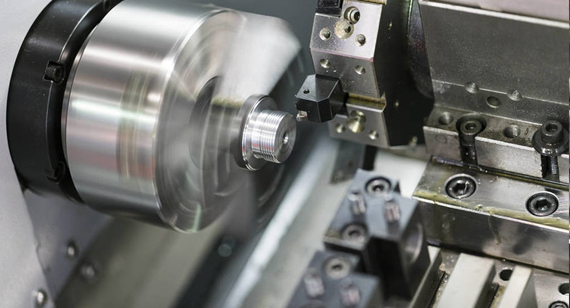
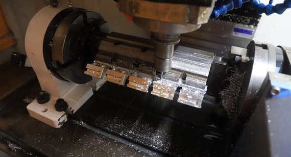
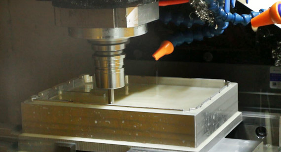
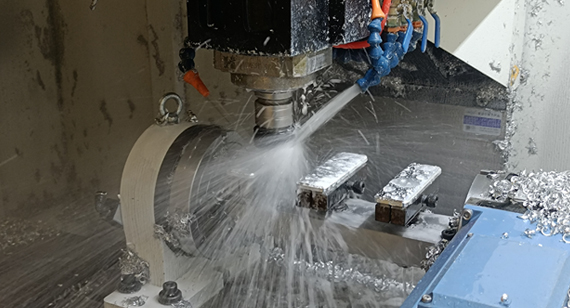
CNC machining utilizes computer-controlled equipment to convert CAD design files into G-code, driving milling cutters or lathes to perform subtractive manufacturing that achieves high precision, excellent repeatability, and maximum structural integrity. Conversely, 3D printing directly interprets CAD files to build parts layer by layer from powdered or molten materials, enabling rapid, cost-effective, and highly flexible additive manufacturing for complex geometries.
Both CNC machining and 3D printing are exceptional rapid prototyping technologies widely used in industries such as drones, automotive, and consumer electronics to accelerate product development and time-to-market. Understanding the key differences in cost, lead time, material limitations, and dimensional accuracy between CNC prototyping and 3D printing is essential to choosing the right process for your specific project—helping you avoid costly budget overruns, delivery delays, or quality mismatches.
In addition to a comprehensive comparison and selection guide, we share a real-world factory case study at the end of this article. You will see how we combined 3D printing and CNC machining to help our client manufacture, validate, and scale production for automotive visual models and functional prototype components.
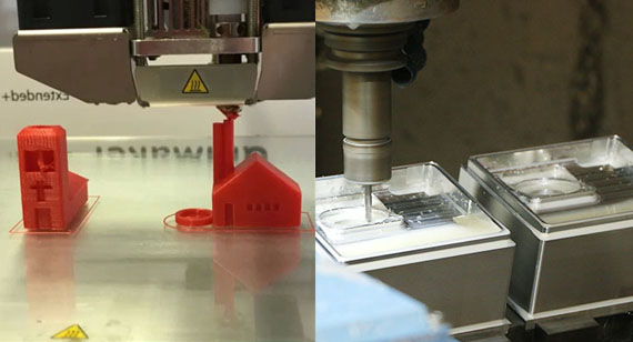
To save you time and prevent costly trial-and-error, we’ve summarized the primary technical trade-offs between 3d printing vs cnc for rapid prototyping below.
| Technical Parameter | CNC Machining | 3D Printing |
| Primary Strength | Superior material strength, tight tolerances, and predictable surface finishes | Complete geometry freedom, no tooling setup, rapid turnarounds |
| Best Prototyping Phase | Functional/load-bearing testing, fit and assembly validation, pre-production runs | Early-stage concept models, visual prototypes, complex internal geometries |
| Dimensional Tolerance | Standard ± 0.05 mm, Precision features down to ± 0.01 mm | Varies by 3D Print Technologies: • FDM: ± 0.2 mm to ± 0.5 mm • SLA / PolyJet: ± 0.1 mm (High detail) • SLS (Nylon): ± 0.3 mm • DMLS/SLM (Metal): ± 0.1 mm to ± 0.2 mm |
| As-Machined Surface Roughness | Smooth and Uniform: Typical Ra 1.6–3.2 μm (Down to Ra 0.8 μm or smooth polished finish) | Layer-Stepped / Textured: • FDM: Rough / Visible layer lines (Ra 6.3–12.5 μm) • SLA: Smooth out of tank (Ra 0.8–1.6 μm) • SLS / DMLS: Matte / Grainy texture (Ra 3.2–6.3 μm) |
| Min. Recommended Wall Thickness | Metals: 0.8 mm Plastics: 1.5 mm (To prevent chatter or deformation) |
FDM: 1.0–1.2 mm SLA / SLS: 0.6–0.8 mm DMLS (Metal): 0.4–0.5 mm |
| Max. Part Size Limit | Very Large: Limited only by CNC bed size (Up to 3,000 × 1,200 × 800 mm or bigger) | Moderate: Limited by printer build chamber (Typically within 600 × 600 × 600 mm; FDM can reach 1,000 mm) |
| Material Strength and Integrity | 100% Isotropic Strength: Cut from solid engineering billets; identical to end-production properties | Anisotropic (Z-axis Weakness): Layer-by-layer bonding creates potential weak planes (SLS/DMLS offer higher density) |
| Design Limitations | Restricted by cutting tool access, internal corner radii, and clamping setups | Virtually none; easily handles undercut features, hollow structures, and internal channels |
| Lead Time (Prototyping) | 3–5 Business Days (Requires CAM programming, tooling and fixture setup) | 1–3 Business Days (Direct print from CAD with minimal preparation) |
To choose the right method for your rapid prototype, you need to understand how the fundamental differences between CNC machining and 3D printing impact real-world part performance, production schedules, and project budgets.
Material Options and Mechanical Properties
The most critical distinction between these two processes lies in material selection and final structural integrity.
CNC machining cuts parts directly from extruded or forged solid material billets. This process preserves 100% of the raw material’s physical properties. As a result, CNC machined prototypes exhibit true isotropic strength, meaning mechanical properties (tensile strength, impact resistance, and thermal tolerance) remain uniform across all X, Y, and Z axes. In addition, CNC machining supports virtually all engineering materials, including metals (Aluminum 6061/7075, Stainless Steel 304/316, Brass, Titanium) and high-performance plastics (POM/Acetal, ABS, PEEK, Nylon, PTFE).
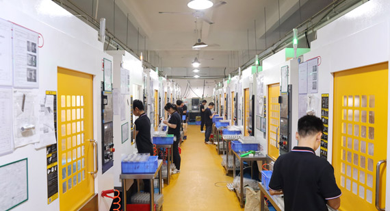
3D printing uses a wide range of materials, including plastics (PLA, ABS, Resin), plastic powders (Nylon PA12, PA11 via SLS), and metal powders (Aluminum AlSi10Mg, Stainless Steel 316L, Titanium Ti6Al4V via DMLS). Modern industrial 3D printing (like SLS and DMLS) is fully capable of high-performance functional testing, though standard layer-by-layer methods (FDM/SLA) may show lower strength along the vertical Z-axis.
Precision, Tolerance and Surface Finish
When validating fit, form, and assembly alignment, dimensional accuracy and surface texture become decisive factors.
Dimensional Accuracy and Tolerances: CNC machines consistently achieve tight engineering tolerances, typically standard ± 0.05 mm (± 0.002'') and down to ± 0.01 mm (± 0.0004'') for precision features like bearing seats or threaded holes. In contrast, 3D printing tolerances vary widely by technology: SLA can reach ± 0.1 mm, whereas FDM usually ranges from ± 0.2 mm to ± 0.5 mm due to thermal expansion, layer stepping, and material shrinkage during cooling.
Surface Finish (Ra Values): CNC machined parts emerge with a clean, smooth, and predictable surface texture directly out of the machine (typically Ra 1.6–3.2μm), which responds exceptionally well to post-processing surface treatments like anodizing, bead blasting, or electroplating. 3D printed parts, however, display visible "stair-stepping" layer lines (especially FDM with Ra 6.3–12.5μm). Achieving a sleek, polished appearance on a 3D print requires manual sanding, filling, or chemical vapor smoothing.
Production Speed and Lead Time
Turnaround times differ drastically depending on part design complexity and setup requirements.
3D Printing (Faster Setup for Single Units): 3D printing is a direct "CAD-to-Print" workflow. It requires virtually no custom fixtures, specialized cutting tools, or complex CAM programming. A technician simply slices the 3D model, sends the file to the machine, and printing begins within minutes. For small, highly intricate individual prototypes or initial concept iterations, 3D printing offers an unrivaled lead time of 1 to 3 days.
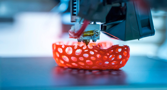
CNC Machining (Upfront Setup, High-Speed Cutting): CNC machining requires upfront engineering preparation, including CAM programming (toolpath generation), cutting tool selection, and custom fixture or vise setup. While this initial setup takes time (leading to a typical lead time of 3 to 5 business days), the actual material removal process is extremely fast. Once programmed and fixtured, machining a second or third piece takes a fraction of the time required to print it.
Cost Considerations: Single Part vs. Batch Prototyping
Single-Part / Low-Volume Prototyping (1–10 Units): For 1 to 10 pieces with complex geometries, 3D printing is usually more economical. Since there are no CAM programming fees or specialized fixturing costs, you only pay for raw material consumption and machine run time.
Small-Batch Prototyping (10–50+ Units): As prototype quantities increase from a few units to small pre-production batches (e.g.,20, or 50 pieces), CNC machining becomes more cost-effective. The upfront CAM programming and setup costs are amortized (divided) across all units, driving down the cost-per-part. In contrast, 3D printing costs scale almost linearly, printing 50 parts takes 50 times as long and consumes 50 times the material, offering negligible volume discounts.
Therefore, you can stay with 3D printing for 1–10 visual or early-stage proof-of-concept models and the design is still changing rapidly. Switching processes to CNC machining for a tiny batch adds unnecessary DFM redesign and CAM setup overhead. Switch to CNC machining when your design is frozen, and you require true production-grade material strength, airtightness, or tight tolerances (± 0.01 mm) for functional testing or end-use pre-production runs (typically 10 to 50+ units). At this stage, CNC machining guarantees inherent part performance while offering better unit-cost efficiency for small batches.
When evaluating 3D printing vs. CNC for rapid prototyping, both technologies offer unique manufacturing advantages depending on your project stage and engineering requirements.
When to Choose CNC Machining for Your Prototype?
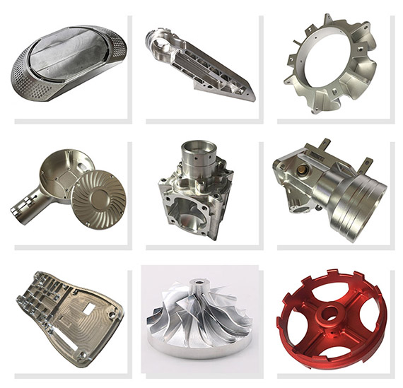
CNC machining is the preferred rapid prototyping process that can provide the pros for your project that:
When to Choose 3D Printing for Your Prototype?
3D printing excels in early-stage prototyping scenarios such as:
How we combined 3D printing and CNC machining to help an automotive client manufacture, validate, and scale production for automotive visual models and functional prototype components.
An automotive client approached our engineering team needing solutions for a new interior dashboard assembly and structural engine bracket prototype. The project presented tight deadlines, complex design geometries, and strict functional validation requirements. The client needed high-detail visual models to evaluate aesthetics and ergonomics for teams’ approvals, alongside high-strength functional metal components capable of passing rigorous mechanical load and thermal stress testing.
To minimize initial costs and accelerate iteration, our engineering team began with additive manufacturing. We utilized SLA 3D printing with high-detail resins to produce full-scale visual dashboard components within 48 hours. This allowed the client’s design team to quickly evaluate surface ergonomics, fitments, and visual aesthetics without investing in expensive tooling setups. During this stage, three minor design iterations were identified and digitally modified in CAD, saving significant time and material costs before finalizing the design.
Once the design was frozen, we transitioned the structural engine brackets and mounting hardware to multi-axis CNC machining. Machined from solid billet Aluminum 6061-T6, these components provided 100% isotropic material strength and precise tolerances down to ±0.01mm. Followed the machining, we then applied custom bead blasting and clear anodizing to ensure good wear resistance and an asethetic finish. These CNC-machined parts successfully passed all on-bench fatigue tests, pressure trials, and fitments with mating engine assemblies.
By effectively combining 3D printing for rapid visual validation with CNC machining for structural performance, we helped the client cut overall prototype development time by 30% and reduce early-stage costs by over 25%. Following successful functional validation, we smoothly scaled the production into a batch production run of 700 CNC-machined units, helping our client achieve a smooth transition from prototype testing to market launch.
Both rapid CNC machining and 3D printing are irreplaceable manufacturing methods in modern product development. Choosing between them comes down to your project’s specific stage, material requirements, and performance goals. For rapid, low-cost concept validation or highly complex geometries, 3D printing is your best starting point. However, for design demands materials with true inherent properties, tight dimensional tolerances, or high-stress mechanical validation, CNC prototype machining delivers the structural integrity and precision you need. Oftentimes, the smartest prototyping strategy involves leveraging both processes in tandem, using additive manufacturing for quick visual mock-ups and subtractive CNC machining for final functional components.
Unsure which process fits your design or budget? Let us solve it for you. Don't let process uncertainty slow down your product launch or cause unexpected cost overruns. Send us your project requirements, and our engineering team will evaluate your designs, recommend the optimal manufacturing route, and provide a fast, budget-friendly prototype quote! [2D Drawings (PDF files), 3D Drawings (IGS/STP/STEP files)].
Send your 2D drawings, 3D CAD models, material requirements, prototype quantity, critical tolerances, surface-finish requirements and target lead time. VMT will review whether CNC machining, 3D printing, or a hybrid manufacturing route is the best fit for your project.
All information and uploaded files are secure and confidential.
1 Tell us what you need
2 Get solution & quote
3 Approve production
Email: inquiry@vimetal.com.cn
Q1: Is CNC machining more expensive than 3D printing for rapid prototyping?
It depends on the part quantity and complexity. For 1 to 3 initial visual concept models with intricate shapes, 3D printing is typically cheaper because it requires zero custom tooling or CAM programming setup. However, for small-batch prototyping (10 to 50+ units), CNC machining becomes more cost-effective per part because the initial setup fees are amortized across the entire batch.
Q2: Can 3D printed metal parts replace CNC machined metal prototypes?
Metal 3D printing (such as DMLS or SLM) can produce fully dense, high-performance functional metal parts, especially for complex organic geometries or internal channels. However, CNC machined metal parts still provide superior surface finishes (Ra 0.8–1.6 μm), tighter dimensional tolerances ( ±0.01 mm ), and 100% isotropic billet strength, making CNC the preferred choice for high-precision mating features and load-bearing applications.
Q3: What if my part has both complex internal channels and tight-tolerance assembly features?
You don't have to choose just one technology. In cases with complex internal geometries that require high-precision bearing seats or sealing faces, a hybrid manufacturing approach is ideal: we first 3D print the raw geometry (using DMLS metal printing) and then use 5-axis CNC post-machining to hit your critical dimensions and tight tolerances.
Q4: How do I prevent warping, deformation, or quality issues in my prototypes?
Warping and deformation usually happen due to uneven stress in thin-walled 3D prints or heat buildup during CNC machining. To avoid these issues, our engineers perform a free DFM (Design for Manufacturability) review before production, adjusting wall thicknesses, optimizing toolpaths, or choosing stress-relieved billets to ensure your prototype arrives dimensionally stable and defect-free.
Q5: What are the best materials for functional prototype machining?
For CNC prototyping, popular structural metals include Aluminum 6061-T6, Aluminum 7075, Stainless Steel 304/316, Brass, and Titanium, alongside engineering plastics like POM (Acetal), ABS, PEEK, Nylon, and PTFE. For functional 3D printing, high-performance materials include Nylon PA12 (via SLS) and Aluminum/Stainless Steel powders (via DMLS).
Q6: Can I combine 3D printing and CNC machining in a single prototype project?
Yes, combining both technologies is an industry best practice. Many development teams use SLA or FDM 3D printing in the early design phase to validate visual aesthetics, ergonomics, and spatial fitment at low cost. Once the CAD design is frozen, they switch to CNC machining to produce high-strength, tight-tolerance functional components for physical testing and pre-production validation.
The technical information and manufacturing advice shared on the VMT website are for general guidance only. While we strive for accuracy, VMT does not guarantee that the processes, tolerances, or material properties mentioned are applicable to every specific project. Any reliance you place on such information is strictly at your own risk. It is the buyer's responsibility to provide definitive engineering specifications for any production orders. Final specifications and service terms shall be subject to the formal contract or quotation confirmed by both parties.


 +86 15099911516




 Read more