16 years one-stop China custom CNC machining parts factory

Hey there I’m VMT Sam!
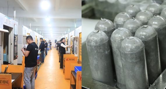
With 25 years of CNC machining experience we are committed to helping clients overcome 10000 complex part-processing challenges all to contribute to a better life through intelligent manufacturing. Contact us now
 255 |
Published by VMT at Jul 01 2022
255 |
Published by VMT at Jul 01 2022


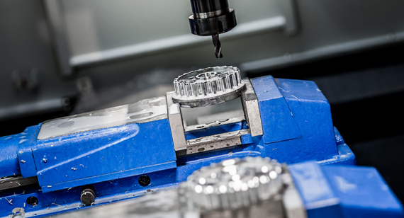
The 29 pieces of CNC machining knowledge organized by the seniors, not much to say, hurry up and read.
1. Influence on cutting temperature: cutting speed, feed rate, amount of cutting edge;
Influence on cutting force: amount of back cut, feed rate, cutting speed;
Influence on tool durability: cutting speed, feed rate, amount of back cut.
2. When the amount of back-engagement is doubled, the cutting force is doubled;
When the feed rate is doubled, the cutting force increases by about 70%;
When the cutting speed doubles, the cutting force gradually decreases;
That is to say, if G99 is used, the cutting speed will increase, and the cutting force will not change much.
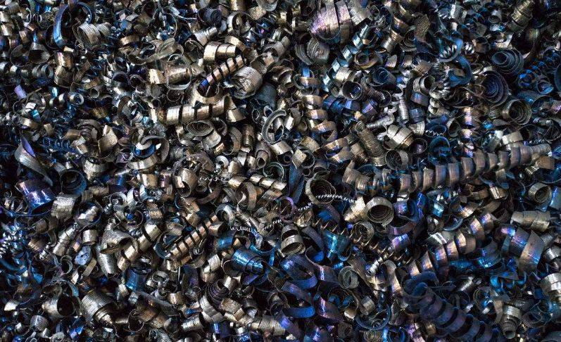
3. According to the discharge of iron chips, it can be judged whether the cutting force and cutting temperature are within the normal range.
4. When the actual value X measured and the diameter Y of the drawing are greater than 0.8, when the concave arc of the car, the turning tool with a secondary declination angle of 52 degrees (that is, our commonly used blade is a turning tool with a main declination angle of 93 degrees of 35 degrees) ) The R drawn from the car may rub the knife at the starting point.
5. The temperature represented by the color of the iron filings:
White is less than 200 degrees
Yellow 220-240 degrees
dark blue 290 degrees
Blue 320-350 degrees
Purple and black greater than 500 degrees
Red is greater than 800 degrees
6. Funac OI mtc generally defaults to the G command:
G69: Not so sure
G21: Metric dimension input
G25: Spindle speed fluctuation detection disconnected
G80: Canned cycle cancellation
G54: Coordinate system default
G18: ZX plane selection
G96 (G97): constant linear speed control
G99: Feed per revolution
G40: Tool nose compensation cancel (G41 G42)
G22: Stored stroke detection ON
G67: Cancel macro program modal call
G64: Not so sure
G13.1: Cancel polar coordinate interpolation
7. The external thread is generally 1.3P, and the internal thread is 1.08P.
8. Thread speed S1200/pitch * safety factor (usually 0.8).
9. Manual tool nose R compensation formula: Chamfer from bottom to top: Z=R*(1-tan(a/2)) X=R(1-tan(a/2))*tan(a) From When going up and down, the chamfer can be changed from minus to plus.
10. Every time the feed increases by 0.05, the speed decreases by 50-80 rpm. This is because reducing the speed means that the tool wear decreases, and the cutting force increases slowly, so as to make up for the increase of the cutting force due to the increase of the feed and the increase of the temperature. impact.
11. The influence of cutting speed and cutting force on the tool is very important. Excessive cutting force is the main reason for the collapse of the tool. The relationship between cutting speed and cutting force: when the cutting speed is faster, the feed remains unchanged, and the cutting force decreases slowly. The higher it is, when the cutting force and internal stress are too large for the blade to withstand, the tool will collapse (of course, there are also reasons such as stress and hardness reduction caused by temperature changes).
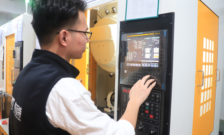
12. During CNC lathe processing, the following points should be paid special attention:
(1) For the current economic CNC lathes in my country, ordinary three-phase asynchronous motors are generally used to achieve stepless speed change through frequency converters. If there is no mechanical deceleration, the output torque of the spindle is often insufficient at low speeds. If the cutting load is too large, it is easy to get bored. car, but some machine tools with gears can solve this problem very well;
(2) As far as possible, the tool can complete the processing of one part or one work shift, especially in the finishing of large pieces, it is necessary to avoid the tool change in the middle to ensure that the tool can be processed at one time;
(3) When turning threads with CNC turning, use a higher speed as much as possible to achieve high-quality and efficient production;
(4) Use G96 as much as possible;
(5) The basic concept of high-speed machining is to make the feed exceed the heat conduction speed, so that the cutting heat is discharged with the iron filings to isolate the cutting heat from the workpiece and ensure that the workpiece does not heat up or heats up less. Therefore, high-speed machining is selected. The cutting speed is matched with the high feed, and a small amount of back cutting is selected;
(6) Pay attention to the compensation of tool nose R.
13. Vibration and chipping often occur during grooving. The root cause of all these is that the cutting force increases and the rigidity of the tool is not enough. The shorter the extension length of the tool, the smaller the clearance angle, the larger the area of the blade, the better the rigidity. The larger the cutting force, the larger the cutting force can be, but the larger the width of the grooving knife, the cutting force it can withstand will increase accordingly, but its cutting force will also increase. Its cutting force is also small.
14. Reasons for vibration when troughing:
(1) The extension of the tool is too long, which reduces the rigidity;
(2) The feed rate is too slow, which will cause the unit cutting force to become larger and cause large vibration. The formula is: P=F/back cutting amount*f P is the unit cutting force F is the cutting force, and the speed is too fast also vibrate;
(3) The rigidity of the machine tool is not enough, that is to say, the tool can bear the cutting force, but the machine tool cannot bear it. To put it bluntly, the machine tool does not move. Generally, new beds do not have such problems. The beds with such problems are either old, Or often encounter machine tool killers.
15. When I had a single car, I found that the size was all right at the beginning, but after a few hours of work, I found that the size had changed and the size was unstable. The reason may be that at the beginning, because the knives were all new, the cutting force was high. It's not very big, but after turning for a period of time, the tool wears out, and the cutting force becomes larger, which causes the workpiece to shift on the chuck, so the size is old and unstable.
16. When using G71, the value of P and Q cannot exceed the sequence number of the whole program, otherwise an alarm will appear: G71-G73 command format is incorrect, at least in FUANC.
17. There are two formats of subroutines in the FANUC system:
(1) The first three digits of P000 0000 refer to the number of cycles, and the last four digits are the program number;
(2) The first four digits of P0000L000 are the program number, and the last three digits of L are the cycle times.
18. The starting point of the arc is unchanged, and the end point is offset by a mm in the Z direction, then the position of the bottom diameter of the arc is offset by a/2.
19. When drilling deep holes, the drill does not grind the cutting groove to facilitate the chip removal of the drill.
20. If you use a tool holder for drilling holes, you can turn the drill bit to change the hole diameter.
21. When drilling a stainless steel center hole, or when drilling a stainless steel hole, the drill bit or center drill center must be small, otherwise it will not move. When drilling with a cobalt drill, do not grind the groove to avoid annealing of the drill bit during the drilling process.
22. According to the process, there are generally three types of blanking: one for one, two for one, and one for the whole bar.
23. When an ellipse appears during threading, it may be that the material is loose, just use a dental knife for a few more cuts.
24. In some systems that can input macro programs, the subroutine cycle can be replaced by macro program charging, which can save the program number and avoid a lot of trouble.
25. If a drill is used for reaming, but the hole jumps a lot, then a flat-bottom drill can be used for reaming, but the twist drill must be short to increase rigidity.
26. If you use a drill directly to drill holes on a drilling machine, the hole diameter may deviate, but if you use a drill machine to ream the holes, the size will generally not run. Around 3 wire tolerance.
27. When turning the small holes (through holes), try to make the swarf roll continuously and then discharge from the tail. The main points of the swarf roll are: first, the position of the knife should be properly raised, second, the appropriate blade inclination, the amount of knife As well as the feed rate, remember that the knife should not be too low, otherwise it will easily break chips. If the secondary declination of the knife is large, the tool bar will not be stuck even if the chip is broken. If the secondary declination is too small, the chips will jam the knife after chip breaking. Rods are prone to danger.
28. The larger the cross-section of the tool bar in the hole, the less easy it is to vibrate the tool, and a strong rubber band can be attached to the tool bar, because the strong rubber band can absorb vibration to a certain extent.
29. When turning copper holes, the tip R of the knife can be appropriately larger (R0.4-R0.8), especially when the taper is under the car, the iron parts may be fine, and the copper parts will be very stuck.

 +86 15099911516


 Read more