15 years one-stop China custom CNC machining parts factory
 640 |
Published by VMT at Jul 28 2024
Comprehensive Guide to CNC Machining Blind Holes
In the realm of CNC machining, hole processing is an indispensable part of the manufacturing process. Blind holes, as a crucial type, are widely used in various precision parts and components. This article aims to provide engineers, technicians, and CNC enthusiasts with a comprehensive guide to blind hole machining, covering the definition of blind holes, machining methods, design considerations, engineering applications, measurement and inspection, and environmental impact, to facilitate efficient and precise blind hole machining practices.
Holes are common structural features in mechanical parts, primarily used for connections, fastening, positioning, or fluid transmission. In CNC machining, the accuracy and surface quality of holes directly affect the overall performance and assembly precision of parts. Blind holes, as the name suggests, are holes that are closed at one end and open at the other, with a depth usually greater than the diameter. They are widely used in scenarios that require a specific depth without penetrating the workpiece.
CNC machining blind holes involves using drills or reamers on a CNC machine to machine blind holes of specified depth, diameter, and shape according to preset program paths and parameters. The advantage of CNC machining lies in its high precision, efficiency, and programmability, ensuring consistency and accuracy in blind hole machining.
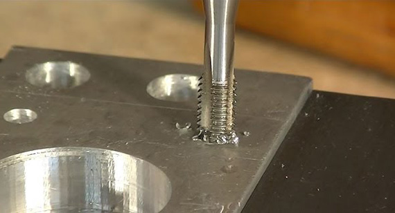
Blind holes are often used with fasteners such as blind screws and blind rivets. These fasteners are designed to achieve secure connections without penetrating the workpiece. The use of blind hole fasteners significantly broadens the application of blind holes in engineering practices, especially in scenarios where maintaining the integrity of the workpiece surface or avoiding backside damage is crucial.
| Type | Description | Common Uses |
|---|---|---|
| Screw | Hex, Phillips, Torx, Slotted | General fastening applications |
| Bolt | Hex, Carriage, U-Bolts, Eye Bolts | Structural and mechanical connections |
| Rivet | Pop Rivets, Blind Rivets, Solid Rivets, Tubular Rivets | Joining materials in aerospace, automotive, and construction |
| Pin | Dowel Pins, Taper Pins, Grooved Pins, Roll Pins | Precision alignment and securing components |
| Anchor | Drop-In Anchors, Sleeve Anchors, Wedge Anchors, Expansion Shields | Secure anchoring in concrete and masonry |
| Toggle | Toggle Bolts, Toggle Wings, Toggle Hooks, Toggle Straps | Hanging heavy objects on walls and ceilings |
| Insert | Threaded Inserts, Helical Inserts, Press-Fit Inserts, Self-Tapping Inserts | Reinforcing threads in soft materials |
| Clip | Spring Clips, Hairpin Clips, Retaining Clips, Reta Clips | Retaining and securing components in place |
| Expanding | Expansion Plugs, Expansion Nuts, Hollow Wall Anchors, Threaded Expansion Inserts | Expanding and anchoring in hollow materials |
| Threaded Rod | Threaded Rods, Threaded Studs, All-Thread Rods, Double-End Studs | Structural support, hanging fixtures, and bracing |
Preparing the Workpiece
Before drilling a blind hole, ensure the workpiece surface is flat, free of oil and debris to avoid affecting drilling precision and drill life. Choose appropriate fixtures based on the material and processing requirements to ensure the workpiece remains stable during machining.
Choosing the Right Drill Bit
The choice of drill bit depends on the workpiece material, hole diameter, depth, and machining precision requirements. For blind hole machining, select drill bits with longer cutting edges and smaller tapers to maintain good cutting performance at the desired depth.
Determining Drilling Depth
Set the drilling depth accurately according to the drawing requirements or actual needs. In CNC programming, specify the stopping position of the drill bit to avoid issues caused by drilling too deep or too shallow.
Starting the Drilling and Monitoring the Depth
Start the CNC machine to begin drilling. During the process, closely monitor the machine's operating status and drilling depth to ensure the drill bit stops at the predetermined depth.
Removing Debris
After drilling, promptly clean out the chips and debris inside and around the hole to avoid affecting subsequent processing or assembly.
Completing and Inspecting the Blind Hole
Finally, use appropriate measuring tools to check the dimensions, shape, and position of the blind hole to ensure it meets design requirements.
Strict Tolerances
Blind hole machining can achieve high-precision size and position control, meeting the strict tolerance requirements for precision parts.
Strength
In certain applications, blind holes can provide additional support or fastening strength, enhancing the structural integrity and stability of parts.
Threaded Holes
Blind holes are often combined with threading to form threaded blind holes, used for installing fasteners or achieving sealed connections.
When selecting taps for machining threaded blind holes, consider factors such as workpiece material, hole diameter, pitch, and machining depth to ensure the quality of the threaded blind hole.
How to Clean Blind Holes?
Cleaning blind holes is an important post-processing step. Methods such as high-pressure air guns, vacuum cleaners, or special cleaning agents can be used. Care must be taken not to damage the hole wall or introduce new debris during the cleaning process.
Blind Hole Drilling Depth Clearance
To ensure the machining precision and surface quality of blind holes, set a reasonable drilling depth clearance. Too small a clearance may lead to drill bit damage or machining difficulty; too large a clearance may affect the depth and shape precision of the hole.
In drawings, blind holes are usually indicated by specific symbols, such as round hole symbols with depth markings or special blind hole symbols. These symbols indicate not only the position and size of the hole but also key information such as the hole depth.
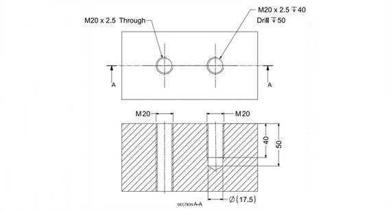
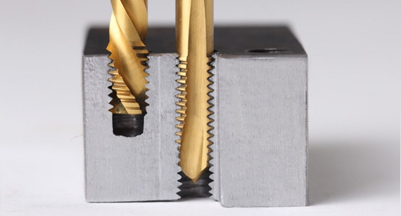
The main difference between blind holes and through holes is whether the hole is closed at one end. Through holes completely penetrate the workpiece, while blind holes are open at one end and closed at the other. This structural difference determines their different uses and machining requirements in engineering applications.
In CNC machining, besides blind holes, there are various other types of holes, such as counterbores, countersinks, spotfaces, counterdrills, and taper holes. Each type has specific uses and machining methods.
Counterbore
Counterbores are mainly used for installing cap screws or bolts, allowing the screw head to be flush with or below the surface. Machining counterbores typically involves drilling a straight hole first, then using a tool with a larger diameter flat-bottom cutting edge to form the counterbore.
Countersink
Countersinks are similar to counterbores but are used for installing fasteners with conical heads, such as countersunk screws or rivets. They require the hole entrance to have a conical or curved shape matching the fastener head to ensure a flush surface. Special countersink drills or milling tools are used for machining.
Spotface
Spotfaces provide a flat contact surface for fasteners without significantly changing the hole depth or diameter. They are used to create a flat area around the hole entrance for washers or flat-head screws. Milling cutters or grinding tools can be used to machine spotfaces.
Counterdrill
Counterdrilling involves deepening or enlarging an existing hole, typically for preparing threaded holes or other holes that need greater depth or diameter. Suitable drills or reamers are selected, and machining depth and diameter are precisely controlled to meet design requirements.
Taper Hole
Taper holes have a diameter that gradually increases from one end to the other. They are important in applications such as bearing installations, fluid control, or when a gradual size change is needed to fit different components. Taper holes are machined using special taper drills or reamers, with precise control over the taper and depth.
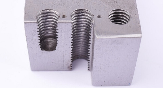
Types of Holes in Machining
In CNC machining, understanding and selecting the appropriate hole type is crucial for ensuring the quality and performance of the part. Blind holes are a common type of hole, and their machining accuracy, surface quality, and positional accuracy directly affect the overall performance and assembly precision of the part.
Blind Holes vs. Through Holes
Blind holes and through holes differ in structure and application. The choice of hole type should be determined based on specific design requirements and engineering applications. Blind holes are suitable for situations where one end needs to be closed and the hole depth needs to be precise, while through holes are suitable for situations where the workpiece needs to be penetrated.
Role of Hole Types in Component Functionality
Different types of holes play various roles in components. For example, blind holes are often used for mounting fasteners, providing support structures, or achieving sealed connections. Countersunk and spot-faced holes are used to keep surfaces flush and accommodate specific shapes of fasteners, while tapered holes might be used for fluid control or bearing installation.
Considerations for Machining Different Hole Configurations
When machining different hole configurations, special attention should be paid to the selection of cutting tools, the setting of machining parameters, the method of clamping the workpiece, and the monitoring and control during the machining process. Reasonable tool selection and parameter settings can ensure machining efficiency and quality. Proper workpiece clamping can prevent vibration and offset during the machining process, and timely monitoring and control can detect and correct issues during machining.
Purposes and Functions
Blind holes have various purposes and functions in engineering applications, including but not limited to connection fixation, support positioning, sealing isolation, and weight reduction. They are widely used in automotive, aerospace, machinery manufacturing, electronic equipment, and other fields.
Common Industries and Use Cases
Automotive Industry: Used in components such as engine blocks, gearbox housings for oil and water channels, and bolt mounting holes.
Aerospace: Used in aircraft structural components for fastener connections, sensor and electronic device installation, and achieving sealed connections.
Machinery Manufacturing: Used in machine tool beds, jigs, and molds for bolt, pin, and locating pin installation.
Electronic Equipment: Used in circuit boards, housings, and heat sinks for fixing elements, connecting circuits, and heat dissipation.
Drilling and Boring Techniques
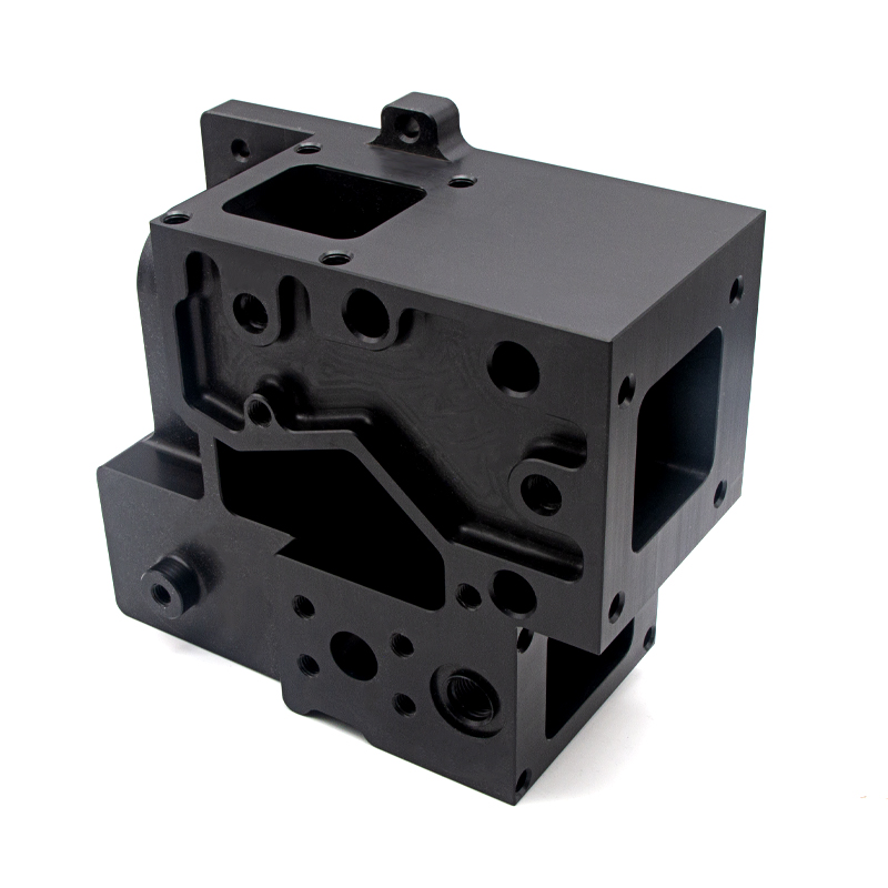
The machining of blind holes typically employs drilling and boring techniques. Drilling is the basic method for initially forming holes, while boring is used to further improve the dimensional accuracy and surface quality of the holes. When machining blind holes, it is necessary to precisely control the drilling depth and boring parameters to ensure that the dimensions and shape of the blind hole meet the design requirements.
Challenges and Considerations
The process of machining blind holes may face challenges such as drill breakage, burrs at the hole entrance, out-of-tolerance hole diameters, and insufficient hole depth. To overcome these challenges, appropriate measures need to be taken, such as selecting suitable drill materials and geometries, optimizing cutting parameters, enhancing the use of coolant, and regularly inspecting and replacing tools.
Planning Components with Blind Holes
Planning components with blind holes requires consideration of the following aspects:
Depth and Diameter: Determine the depth and diameter of the blind hole based on design requirements and engineering applications.
Material Characteristics: Different materials pose different challenges for blind hole machining. For example, hard materials like stainless steel and titanium alloys require sharper tools and lower cutting speeds, while soft materials like aluminum and copper are prone to burrs and deformation, requiring control of cutting force and feed rate. Additionally, the thermal conductivity, hardness, and toughness of the material will affect thermal stress and cutting forces during machining, thereby impacting the quality of the blind hole.
Placement and Direction: The position and direction of the blind hole should be determined based on the overall structure and functional requirements of the part. A reasonable hole layout can reduce stress concentration and improve the strength and rigidity of the part. Simultaneously, the direction of the blind hole should match the load direction of the part to ensure the installation effect of fasteners and the durability of the part.
Interaction with Other Features: The machining of blind holes should also consider their interaction with other features on the part (such as grooves, bosses, threads, etc.). These features may restrict the entry angle of the tool or increase the complexity of machining, so sufficient consideration and planning need to be done at the design stage.
Importance of Hole Position and Direction
The position and direction of the blind hole have a significant impact on the performance and assembly precision of the part. An unreasonable hole layout may lead to stress concentration, reducing the strength and rigidity of the part. Deviation in the direction of the hole may result in the incorrect installation of fasteners or affect the overall function of the part. Therefore, the position and direction of the hole must strictly follow design requirements during design and machining to ensure accuracy.
Tolerance, Surface Finish, and Material Considerations
Tolerance control directly relates to the assembly precision and performance stability of the part. Surface finish affects the wear resistance, corrosion resistance, and sealing performance of the part. When selecting materials, it is necessary to comprehensively consider the strength, toughness, machinability, and cost of the material to ensure the quality and efficiency of blind hole machining.
Advantages in Machining and Usage
Enhanced Aesthetics: Blind holes can be hidden inside the part, avoiding holes or protrusions on the part's surface, thus maintaining a clean and aesthetic appearance.
Increased Strength and Reduced Stress Concentration: A reasonable blind hole layout can reduce stress concentration and increase the strength and rigidity of the part.
Weight Reduction and Space Saving: Blind holes can reduce material usage, lowering the weight and cost of the part and saving space.
Enhanced Structural Integrity: Blind holes can be used with fasteners to enhance the structural integrity and stability of the part.
Sealing Compartments: In some applications, blind holes can serve as part of a sealing structure to isolate or control the flow of fluids or gases.
Thread Fastening: Blind holes can be threaded for the installation of threaded fasteners, providing reliable connections and fixation.
Trapped Debris: Chips and debris generated during blind hole machining may be difficult to completely remove, leading to excessive residues inside the hole and affecting machining quality and subsequent use.
Machining Complexity: Machining blind holes requires precise control of drilling depth and diameter, increasing the difficulty and complexity of machining.
Material Warping or Deformation: During machining, due to the cutting force and thermal stress, the part may warp or deform, affecting the precision and position of the blind hole.
Machining Complexity: For certain special materials or complex-shaped blind holes, machining difficulty may be higher, requiring special tools and processes.
Potential for Stress Concentration: An unreasonable blind hole layout may lead to stress concentration, reducing the strength and durability of the part.
Assembly Considerations: During the installation of fasteners, ensuring that the fasteners can correctly enter the blind hole and achieve the predetermined fastening force is necessary to avoid damaging the part or affecting assembly precision.
Quality Control Methods to Ensure Blind Hole Precision
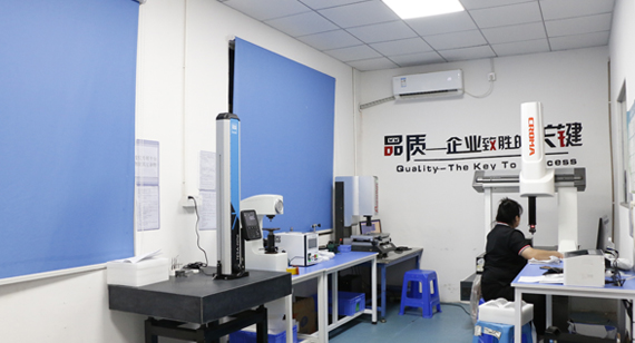
To ensure the precision and quality of blind holes, appropriate measurement and inspection techniques should be employed. Common quality control methods include:
Coordinate Measuring Machine (CMM): CMM is a high-precision three-dimensional measuring device that can accurately measure the position, depth, diameter, and shape of blind holes.
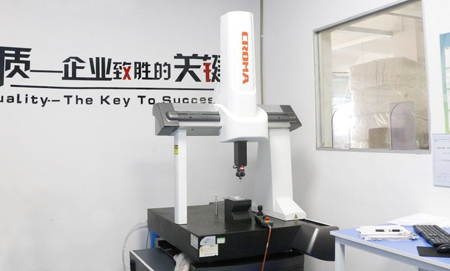
Surface Profilometer: A surface profilometer is used to measure the contour shape and surface roughness of the hole entrance to ensure the smoothness and dimensional accuracy of the hole entrance.
Non-Destructive Testing (NDT): Non-destructive testing techniques such as ultrasonic testing and X-ray testing can be used to detect internal quality issues of the blind hole, such as cracks and pores.
Metrology Tools and Inspection Processes: Use vernier calipers, bore gauges, and other metrology tools to check the dimensions of the blind hole, combined with visual inspection and tactile inspection methods to ensure machining quality.
Environmental Impact of Blind Hole Machining
The machining of blind holes generates cutting fluids, chips, and waste that impact the environment. To achieve sustainable machining, the following measures should be taken:
Reasonable Use of Cutting Fluids: Select environmentally friendly cutting fluids, reduce the amount of cutting fluids used, and adopt recycling and wastewater treatment systems to minimize environmental impact.
Chip Recovery and Treatment: Classify, recover, and treat chips generated during machining to avoid random disposal and environmental pollution.
Energy Conservation and Emission Reduction: Optimize machining processes and machine tool parameters to reduce energy consumption and emissions during machining. For example, selecting appropriate cutting speeds, feed rates, and cutting depths can reduce power consumption and cutting heat. Additionally, regularly maintain and service machine tools to ensure their operational efficiency and reduce unnecessary energy loss.
Use of Environmentally Friendly Materials: Prioritize environmentally friendly materials during part design and material selection to reduce the use and emission of harmful substances. Environmentally friendly materials are not only eco-friendly but also improve the recyclability and reuse of parts.
Green Manufacturing Philosophy: Implement the green manufacturing philosophy throughout the entire process of blind hole machining, including process design, material selection, machining process, quality control, and waste treatment. Through continuous improvement and innovation, achieve low energy consumption, low emissions, and low pollution, contributing to sustainable development.
Selecting the Right Drill Bits and Taps
Drill Bit Selection:
Material Selection: Choose drill bit materials according to the workpiece material. For high-hardness materials, tungsten carbide or ceramic drill bits are ideal, while high-speed steel (HSS) drill bits are suitable for easier-to-machine materials.
Drill Shape: Select the drill shape based on the blind hole's shape and depth. For deep hole drilling, long drill bits or center drills are typically needed.
Drill Precision: The precision of the drill bit directly affects the hole's machining quality. Select drill bits with appropriate precision according to the machining requirements. For example, nano-coated center drills are suitable for machining holes with high surface finish requirements.
Tap Selection:
Threading Blind Holes: For threading blind holes, opt for spiral taps or forming taps to ensure smooth chip evacuation and prevent clogging inside the hole.
Tap Type and Size: Choose the appropriate tap type and size based on the thread specifications and material. For high-precision threads, forming taps can be used to achieve higher finish and precision.
Drilling Deep Holes
Tool Rigidity: Pay special attention to tool rigidity when drilling deep holes to avoid vibrations and deviations caused by excessively long or insufficiently rigid tools.
Cutting Parameters: Use appropriate cutting parameters, such as cutting speed, feed rate, and cutting depth, to ensure tool stability during the machining process.
Tool Design: Employ unequal tooth spacing reamers or rigid coupling methods if necessary to enhance tool rigidity and stability.
Position and Direction of the Hole
Verification Before Machining: Carefully verify the drawings and process requirements to ensure the accuracy of the hole's position and direction.
Proper Fixtures: Use suitable fixtures and positioning devices to ensure the stability and accuracy of the workpiece during machining.
CNC Programming and Simulation: For complex shapes and positions, utilize CNC programming and simulation technologies to improve machining precision and efficiency.
Hole Diameter
Diameter Selection: Choose the appropriate drill bit diameter and cutting parameters according to the machining requirements and drawing dimensions to ensure the accuracy and consistency of the hole diameter.
Periodic Inspection: Regularly check the hole diameter during machining. Adjust cutting parameters or replace the drill bit if deviations occur.
Cleaning Blind Holes
Post-Machining Cleaning: Clean the blind hole after machining to remove chips and impurities.
Cleaning Methods: Use high-pressure air, solvent cleaning, or specialized cleaning tools.
Inspection After Cleaning: Ensure the hole is free of residues post-cleaning to facilitate subsequent processes.
Appropriate Equipment and Tools: Use suitable equipment such as CNC drilling machines, proper drill bits, and taps.
Reasonable Machining Process: Develop a comprehensive machining process including tool selection, cutting parameter settings, and machining steps.
Process Control: Regularly inspect tool wear, stability of cutting parameters, and accuracy of hole position and dimensions.
Quality Control: Post-machining, inspect the hole diameter, depth, and surface roughness to ensure the quality meets the requirements.
As a professional CNC machining factory, VMT in China offers customized CNC blind holes parts services. By working closely with customers to understand specific machining requirements and drawing dimensions, VMT can tailor suitable machining solutions, using high-quality materials and advanced equipment to ensure high-precision, high-quality, and short lead-time for blind hole parts.

Drilling blind holes is a common yet crucial operation in machining, requiring comprehensive consideration of material characteristics, machining equipment, tool selection, and cutting parameter settings. By selecting the right drill bits and taps, optimizing the drilling gap, ensuring accurate hole position and direction, controlling hole diameter, and cleaning blind holes, the correctness and stability of blind hole machining can be ensured. Strengthening process control and quality control is also key to guaranteeing machining quality.
What is a Threaded Blind Hole?
A threaded blind hole is a hole with threads machined inside it, typically used in situations requiring threaded connections without needing to penetrate the entire workpiece.
What Materials Can Be Used for Blind Hole Machining?
Almost all metal materials (such as steel, aluminum, copper) and non-metal materials (such as plastics, ceramics) can be machined for blind holes using CNC techniques. However, the machining difficulty and process requirements may vary for different materials.
What is Hole Machining?
Hole machining refers to the process of creating various types of holes in a workpiece, including drilling, reaming, tapping, and boring. It is a vital part of mechanical machining, widely applied in the manufacturing of various mechanical parts and components.
What is the Difference Between a Blind Hole and a Through Hole?
The primary difference between a blind hole and a through hole is whether the hole penetrates the workpiece. A blind hole does not penetrate the workpiece and is used for fastening, mounting, or connecting without needing to go through the material, while a through hole goes through the workpiece and is used for fluid passage, wire threading, or connecting two parts.
What are the Standard Measurement and Inspection Procedures for Blind Holes?
Diameter Measurement: Use inside micrometers or bore gauges to measure the hole diameter.
Depth Measurement: Use depth gauges to measure the hole depth.
Position and Direction Check: Use coordinate measuring machines (CMM) or projectors to check the hole's position and direction.
Surface Roughness Measurement: Use a surface roughness tester to measure the hole's entrance and wall roughness.
Thread Inspection (for threaded blind holes): Use thread ring gauges or plug gauges to check the thread profile, pitch, and major diameter.
Geometric Tolerance Inspection: Inspect roundness, cylindricity, and coaxiality according to the drawing requirements.
Non-Destructive Testing: For critical parts or special requirements, non-destructive testing methods such as ultrasonic or X-ray inspection may be necessary to detect internal defects.
By following these steps, the machining quality of blind holes can be comprehensively and accurately inspected and evaluated, ensuring the parts meet design and usage requirements. In actual production, the inspection procedures and methods should be flexibly adjusted according to specific conditions to improve inspection efficiency and accuracy.
