15 years one-stop China custom CNC machining parts factory
 219 |
Published by VMT at Dec 29 2024 | Reading Time:About 10 minutes
Designing parts for CNC machining can be a daunting task, especially for those new to the process. Incorrect designs can lead to increased production costs, longer machining times, and even part failures, ultimately impacting your project's success and your business's bottom line. Understanding the principles of CNC machining parts design is essential for creating efficient, high-quality components that meet your specifications and performance requirements.
An Effective Guide to CNC Machining Parts Design
Effective CNC machining parts design involves adhering to best practices such as designing with appropriate tool sizes, maintaining optimal cavity depths, considering machine axis limitations, and avoiding excessively small features. By following these guidelines, you can ensure your designs are machinable, cost-efficient, and produce high-quality parts consistently.
To achieve optimal results in your CNC machining projects, it's crucial to grasp the fundamental design rules, understand the limitations of the CNC process, and apply advanced strategies for complex features. This complete guide will walk you through each essential aspect of CNC machining parts design, ensuring you have the knowledge and tools to create successful, manufacturable parts.
What is the CNC Machining Process?
CNC machining is a manufacturing process that uses computerized controls and precision tools to remove material from a workpiece, creating highly accurate and complex parts. The process involves programming a CNC machine with specific instructions, which guide the machine's movements and operations to produce the desired geometry.
CNC machining encompasses various techniques, including milling, turning, drilling, and grinding, each suited to different types of operations and materials. The key advantage of CNC machining is its ability to produce consistent, repeatable parts with tight tolerances, making it indispensable in industries such as aerospace, automotive, medical devices, and consumer electronics.
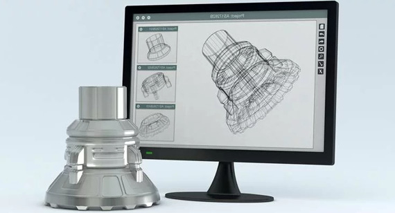
The CNC machining process begins with a detailed design, typically created using CAD (Computer-Aided Design) software. This design is then translated into a set of instructions using CAM (Computer-Aided Manufacturing) software, which generates the tool paths and machine operations required to fabricate the part. The CNC machine reads these instructions and precisely controls the cutting tools to remove material layer by layer, achieving the final shape.
Understanding the CNC machining process is fundamental to effective parts design. By recognizing how the machine interprets and executes the design, designers can optimize their models to reduce machining time, minimize waste, and ensure that complex features are accurately produced. This synergy between design and manufacturing enables the creation of high-quality, functional components tailored to specific application needs.
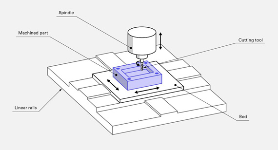
Designing parts for CNC machining requires a keen understanding of both the capabilities and limitations of the machining process. By adhering to fundamental design principles, engineers can create components that are not only manufacturable but also cost-effective and efficient. The following sections outline essential design rules that should be considered when designing parts for CNC machining.
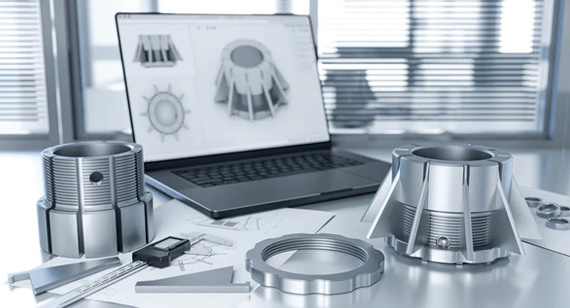
Design Parts that are Easy to Machine with Large Diameter Tools
When designing parts for CNC machining, it's crucial to consider the tools that will be used in the process. Large diameter tools are generally more efficient and cost-effective for bulk material removal. Designing features that accommodate these tools can significantly reduce machining time and tool wear.
For instance, avoiding unnecessarily small diameters for holes and channels allows larger tools to be used, speeding up the production process. Additionally, ensuring that the design does not have intricate features that require multiple tool changes can streamline the machining workflow, reducing the likelihood of errors and enhancing overall efficiency.
By designing with large diameter tools in mind, you can optimize the machining process, leading to faster turnaround times and lower production costs. This approach is especially beneficial for high-volume manufacturing where efficiency and consistency are paramount.
The Depth of a Cavity Should Not Exceed Four Times its Width
A key principle in CNC machining design is maintaining optimal cavity depths relative to their widths. Cavities that are too deep can pose significant challenges during machining, leading to increased tool wear, longer machining times, and potential part deformation.
As a general rule, the depth of a cavity should not exceed four times its width. This ratio ensures that the tool can adequately reach and machine the cavity without compromising the part's structural integrity. Adhering to this guideline helps prevent issues such as chip evacuation problems and tool breakage, which can arise from overly deep cavities.
By keeping cavity depths within the recommended limits, you enhance the machinability of the part, reduce production costs, and improve the overall quality of the final product. This practice is especially important for parts with complex geometries, where maintaining precise dimensions and structural stability is critical.
When Designing, Consider the Main Directions Allowed by the Machine and its Standard Number of Axes
CNC machines operate within specific movement parameters, dictated by their axis configurations. Understanding the machine's main directions and the number of axes it possesses is essential for designing parts that are manufacturable without requiring excessive reorientation or complex tooling setups.
Most CNC machines operate on three primary axes: X, Y, and Z. However, more advanced machines may feature additional axes, such as A and B, allowing for greater flexibility in machining complex geometries. When designing parts, it's important to align features with these axes to facilitate easier machining and reduce the need for multiple setups.
For instance, orienting cavities, holes, and other features along the machine's main directions ensures that they can be accessed and machined efficiently. This consideration minimizes the risk of tool collision, reduces machining time, and enhances the overall accuracy of the part.
By aligning your design with the machine's operational capabilities, you can streamline the manufacturing process, lower production costs, and achieve higher precision in the final product. This strategic approach to design not only improves manufacturability but also contributes to the scalability and repeatability of the machining process.
Do Not Use Sizes Smaller Than 20 Points When Machining Text
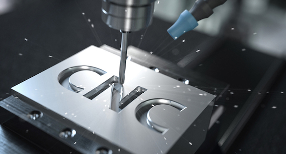
When incorporating text or lettering into CNC machined parts, it is essential to maintain legibility and machinability by adhering to minimum size guidelines. A recommended minimum size is 20 points, which ensures that the text is clear and easy to read without being overly intricate.
Designing text features smaller than this size can lead to difficulties during machining, such as tool deflection or incomplete engraving, resulting in illegible or flawed text. Additionally, smaller text sizes increase the risk of part deformation and surface imperfections, which can compromise both the aesthetic and functional aspects of the part.
By adhering to a minimum text size of 20 points, you ensure that the text is sufficiently large to be machined accurately and remains legible in the final product. This practice enhances the overall quality of the part and reduces the likelihood of errors and rework during the manufacturing process.
Maintaining appropriate text sizes not only improves the machinability of the part but also enhances its professional appearance and user-friendliness. Whether used for labeling, branding, or informational purposes, clear and legible text contributes to the functionality and appeal of the CNC machined component.
While CNC machining offers remarkable precision and flexibility in manufacturing complex parts, it is not without its limitations. Understanding these constraints is crucial for effective design and successful manufacturing outcomes. This section explores the primary limitations of CNC design, focusing on tool geometry and tool access, which significantly impact the machinability and cost-efficiency of CNC machining projects.
Tool Geometry
One of the fundamental limitations in CNC design relates to tool geometry. The shape, size, and type of cutting tools available directly influence the complexity and feasibility of the machined features. CNC machines are equipped with a variety of tools, each designed for specific operations such as milling, turning, drilling, or engraving.
However, the limitations of tool geometry mean that certain intricate or highly detailed features may be challenging or impossible to machine effectively. For example, internal corners, undercuts, and small-radius fillets require precise tool control and appropriate tool selection. If the tool cannot adequately reach or shape these features, it can result in incomplete machining, surface imperfections, or increased tool wear.
Additionally, the geometry of the tool affects the achievable tolerances and surface finishes. Sharp tool edges can produce finer details and smoother surfaces, but they are more prone to wear and breakage, especially when machining hard materials or performing high-speed operations.
Understanding the limitations imposed by tool geometry allows designers to create parts that are within the capabilities of available tools, ensuring that all features can be accurately and efficiently machined. This awareness helps in optimizing designs to minimize machining challenges, reduce production costs, and achieve high-quality results.
Tool Access
Another significant limitation in CNC design is tool access. Tool access refers to the ability of the cutting tool to reach and machine specific areas of the part without interference from other features or the workholding setup. Effective tool access is essential for machining internal cavities, recessed features, and complex geometries.
When tool access is restricted, it can lead to incomplete machining, requiring additional setups or manual interventions to achieve the desired features. This not only increases production time and costs but also introduces potential errors and inconsistencies in the machined parts.
Designers must consider the orientation and arrangement of features to ensure that tools can access all necessary areas of the part. This may involve simplifying geometries, avoiding excessive undercuts, or designing features that can be machined sequentially without interference.
Additionally, the choice of machining strategy, such as the sequence of operations and the use of multi-axis machines, plays a critical role in overcoming tool access limitations. By strategically planning the machining process and optimizing tool paths, designers can enhance tool access, improve machining efficiency, and ensure that all part features are accurately produced.
In conclusion, tool geometry and tool access are key limitations in CNC design that must be carefully considered during the design phase. By understanding and addressing these constraints, designers can create parts that are both manufacturable and cost-effective, leveraging the full potential of CNC machining technology.
Creating designs optimized for CNC machining involves a detailed understanding of both the design principles and the machining capabilities. This CNC design guide provides comprehensive insights into various aspects of designing parts for CNC machining, including handling holes and pockets, managing cavity depths, designing inside edges, floors, thin walls, holes, threads, small features, tolerances, text and fonts, and implementing best practices. By following this guide, designers can ensure that their parts are manufacturable, cost-effective, and meet the desired quality standards.
Holes and Pockets
Recommended Cavity Depth
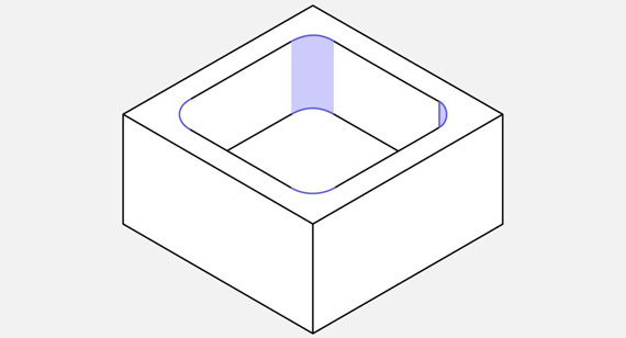
When designing holes and pockets for CNC machining, it is essential to manage cavity depths to ensure machinability and part integrity. The recommended cavity depth should generally not exceed four times the cavity's width. This guideline helps in preventing excessive tool wear, reducing machining time, and avoiding potential part deformation.
For instance, if a pocket has a width of 10mm, its depth should not exceed 40mm. Adhering to this ratio facilitates effective chip evacuation, minimizes tool deflection, and ensures a consistent surface finish. In cases where deeper cavities are necessary, designers should consider breaking them into multiple, shallower pockets or redesigning the part to accommodate standard machining practices.
By maintaining optimal cavity depths, designers can enhance the manufacturability of their parts, ensuring that all features are machined accurately and efficiently without compromising the part's structural integrity.
Deep Cavity Milling
Deep cavity milling presents unique challenges in CNC machining due to the increased material removal and tool engagement required. To effectively machine deep cavities, several strategies can be employed:
By incorporating these strategies, CNC machinists can successfully machine deep cavities, achieving the desired dimensions and surface finishes while minimizing production challenges and costs.
Inside Edges
Vertical Corner Radius
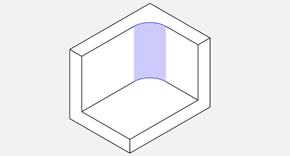
Designing inside edges with appropriate corner radii is crucial for CNC machining, as sharp corners can be difficult to machine and may lead to tool wear or part deformation. A recommended minimum vertical corner radius is typically between 0.2mm to 0.5mm, depending on the material and machining parameters.
A smooth corner radius allows the cutting tool to engage the material more effectively, reducing stress concentrations and enhancing the part's structural integrity. Additionally, proper corner radii contribute to improved surface finishes, minimizing the risk of surface defects and improving the overall aesthetic quality of the part.
When designing inside edges, it is essential to consider the capabilities of the machining tools and the material properties to determine the optimal corner radius. Balancing the need for precision with the practical limitations of the machining process ensures that the part can be manufactured efficiently without compromising its design intent.
Recommended
In addition to maintaining appropriate corner radii, designers should ensure that all inside edges are accessible to the cutting tools. This involves aligning the part's features with the machine's axis orientations and avoiding excessive undercuts that may restrict tool access.
Moreover, incorporating chamfers or fillets at inside edges can further enhance machinability and part durability. Chamfers can provide clearance for tools, while fillets can distribute stress more evenly, reducing the risk of part failure under load or vibration.
By adhering to these recommendations, designers can create parts with well-defined inside edges that are both aesthetically pleasing and manufacturable, ensuring high-quality outcomes in CNC machining projects.
Floor Radius
Recommended
When designing the floors of pockets or cavities, it is advisable to incorporate a minimum radius to facilitate smooth tool movement and reduce the likelihood of surface imperfections. A recommended floor radius is typically between 0.5mm to 1mm, depending on the part's design requirements and the material being machined.
A rounded floor radius minimizes tool deflection and chip clogging, ensuring that the cutting tool can traverse the cavity floor evenly and maintain consistent cutting performance. This approach also enhances the surface finish of the cavity, reducing roughness and improving the part's overall appearance.
Furthermore, a rounded floor radius can contribute to the part's structural integrity by distributing stress more evenly, reducing the risk of cracking or deformation under load.
Possible
In cases where a smaller floor radius is necessary for design aesthetics or functional requirements, careful consideration must be given to the machinability of the feature. While smaller radii can be achieved, they may require specialized tooling and more precise machining parameters to maintain accuracy and surface quality.
Designers should evaluate the trade-offs between design complexity and manufacturability, ensuring that any deviations from the recommended floor radius do not compromise the part's performance or increase machining complexity and costs excessively.
By balancing design intentions with practical machining considerations, designers can create effective and functional cavity floors that meet both aesthetic and performance criteria.
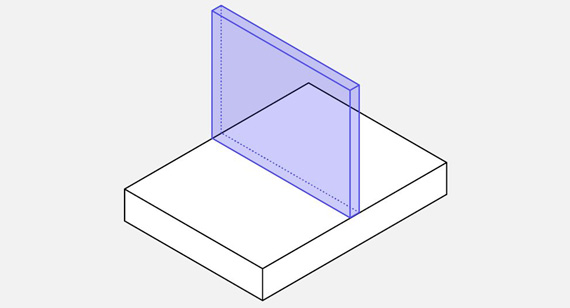
Minimum Wall Thickness
Thin walls are a common feature in many CNC machined parts, offering benefits such as reduced material usage and lightweight designs. However, maintaining an appropriate wall thickness is crucial to ensure the part's structural integrity and machinability.
A minimum wall thickness is typically recommended to be no less than 1.0mm to 2.0mm, depending on the material and the part's functional requirements. Thinner walls may be more susceptible to deformation, vibration, and breakage during machining and in the final application.
Designers should consider the forces and stresses that the part will encounter in its intended use, ensuring that the walls are thick enough to withstand these conditions without compromising the part's durability or performance.
Recommended
When designing thin walls, it is essential to balance material efficiency with structural strength. Incorporating features such as ribs, gussets, or fillets can enhance the rigidity and stability of thin walls, preventing deformation and increasing the part's overall robustness.
Additionally, ensuring that thin walls are uniformly distributed and free from sharp transitions can improve machinability, reducing the risk of tool deflection and enhancing the surface finish.
By adhering to recommended wall thicknesses and incorporating reinforcing features, designers can create parts that are both lightweight and strong, optimizing material usage without sacrificing performance.
Possible
In certain applications, extremely thin walls may be required for specific functional or aesthetic purposes. While challenging, these designs can be achieved with careful consideration of the machining process and the use of appropriate tools.
Designers should collaborate closely with CNC machining experts to evaluate the feasibility of machining thin walls, selecting the right materials and machining strategies to achieve the desired results without compromising the part's integrity.
By leveraging advanced CNC machining techniques and materials, it is possible to create intricate parts with thin walls that meet both design and performance specifications.
Hole
Diameter
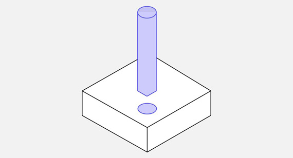
The diameter of holes is a critical aspect of CNC machining parts design, influencing both the machinability and functionality of the final product. When designing holes, it is important to consider the minimum and maximum diameter requirements based on the part's application and the capabilities of the CNC machine.
A recommended minimum hole diameter is typically around 2mm to 3mm, depending on the material and machining parameters. Smaller holes may be challenging to machine accurately and may require specialized tooling, such as micro-drills, which can increase production costs and machining time.
Conversely, excessively large holes may weaken the part's structural integrity and should be avoided unless required for specific functional purposes.
Possible
Designing for larger hole diameters can be beneficial in applications where ease of assembly, component insertion, or fluid flow is required. However, it is important to ensure that the hole diameter is proportionate to the part's overall design and does not compromise its strength or stability.
Additionally, incorporating features such as chamfers or countersinks at the entrance of large holes can facilitate easier insertion of components and enhance the overall functionality of the part.
By carefully selecting appropriate hole diameters and incorporating complementary design features, designers can create parts that meet their functional requirements while maintaining manufacturability and structural integrity.
Maximum Depth
Recommended
Maintaining a maximum depth for holes is essential to ensure machinability and prevent part deformation. A general guideline is to limit the depth of a hole to approximately three to five times its diameter. This ratio helps in facilitating effective chip evacuation, reducing tool wear, and maintaining accurate hole dimensions.
For example, a hole with a diameter of 10mm should ideally not exceed a depth of 30mm to 50mm. Adhering to this recommendation ensures that the hole can be machined efficiently without introducing excessive stresses or compromising the part's structural integrity.
Typical
In typical CNC machining operations, holes are machined to depths that align with the recommended depth-to-diameter ratio, ensuring consistency and precision across all machined parts. This standardization facilitates efficient machining workflows, reduces the likelihood of errors, and enhances the overall quality of the final product.
Additionally, maintaining consistent hole depths simplifies the programming and machining process, allowing for more predictable outcomes and streamlined production schedules.
Possible
In cases where deeper holes are required, designers can employ strategies such as step drilling, using specialized deep-hole drilling techniques, or incorporating features that facilitate chip evacuation. These approaches enable the machining of deeper holes while maintaining accuracy and preventing issues such as chip clogging or tool deflection.
However, deeper holes may increase machining time and tool wear, so it is important to evaluate the necessity of such features against their impact on production efficiency and costs.
By implementing these strategies, designers can achieve the desired hole depths while mitigating potential challenges associated with deep-hole machining.
Thread Size
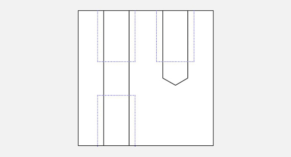
Designing threaded holes requires careful consideration of the thread size to ensure proper functionality and machinability. The thread size should be selected based on the intended use, load-bearing requirements, and compatibility with standard fasteners.
A minimum thread size is typically recommended to be at least M3 (3mm diameter) for most applications, allowing for sufficient strength and ease of assembly. Smaller thread sizes may be more challenging to machine accurately and may require specialized tooling, increasing production costs and time.
Minimum
A minimum thread size of M3 is advisable to ensure that the threads are robust enough to handle the expected loads and stresses. Smaller thread sizes, such as M2 (2mm diameter), can be used for lightweight applications or where minimal fastening strength is required. However, they may not provide adequate holding power in high-stress environments.
Additionally, extremely small thread sizes may be difficult to machine accurately, leading to incomplete threading or poor thread quality.
Recommended
For most CNC machining applications, a thread size of M4 to M6 (4mm to 6mm diameter) is recommended, providing a good balance between strength, functionality, and machinability. These thread sizes are commonly used in a variety of industries, offering compatibility with standard fasteners and ensuring reliable assembly.
By selecting appropriate thread sizes, designers can enhance the functionality and assembly of their CNC machined parts, ensuring that the threads are robust and effective in their intended applications.
Thread Length
Minimum
When designing threaded holes, it is important to specify a minimum thread length to ensure adequate engagement between the thread and the fastener. A general guideline is to provide at least 1.5 to 2 times the diameter of the fastener in thread length. For instance, an M6 (6mm diameter) fastener should have a thread length of at least 9mm to 12mm.
Adequate thread length ensures that the fastener is securely anchored, providing the necessary holding power and preventing loosening under load or vibration.
Recommended
For optimal performance, a thread length of 2 to 3 times the fastener diameter is recommended. This ensures sufficient thread engagement, enhancing the strength and reliability of the connection. Longer thread lengths also contribute to better load distribution and increased resistance to stripping or pulling out.
In applications where high load-bearing capacity is required, such as in structural components or heavy machinery, incorporating longer thread lengths can significantly improve the overall durability and safety of the assembly.
Conclusion
Specifying appropriate thread lengths is essential for ensuring the integrity and functionality of threaded connections in CNC machined parts. By adhering to recommended thread length guidelines, designers can create robust and reliable connections that meet the performance requirements of their applications.
Small Features
Minimum Hole Diameter
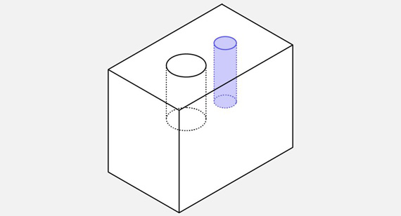
In CNC machining design, incorporating small features such as tiny holes or intricate details requires careful consideration to ensure machinability and part integrity. The minimum hole diameter should typically not be smaller than 1.0mm to 1.5mm, depending on the material and machining parameters.
Designing features below this threshold can pose challenges in terms of tool selection, machining precision, and part strength. Extremely small features may also be more susceptible to errors or defects during the machining process, leading to reduced functionality or compromised structural integrity.
Recommended
For most CNC machining applications, a recommended minimum hole diameter of 1.5mm to 2.0mm ensures that small features are machinable without introducing excessive challenges or compromising part quality. This size allows for the use of standard micro-drills or specialized tools, facilitating accurate and efficient machining of small features.
Additionally, maintaining a consistent minimum size across all small features enhances the overall manufacturability and quality of the part, ensuring that all details are precise and functional.
Possible
In specific applications where smaller hole diameters are necessary, designers can explore advanced machining techniques or utilize specialized equipment to achieve the desired dimensions. However, it is important to evaluate the feasibility and cost implications of machining extremely small features, as they may require additional processing steps, higher machining precision, and more expensive tooling.
By carefully assessing the necessity and practicality of small features, designers can make informed decisions that balance design complexity with manufacturability, ensuring that the final CNC machined parts meet both functional and quality standards.
Typical
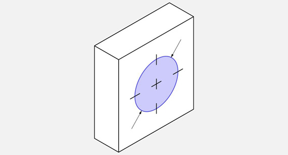
Tolerances define the allowable deviations from the specified dimensions of a CNC machined part. Typical tolerance ranges vary based on the part's complexity, material, and functional requirements. For most CNC machining operations, standard tolerances fall within ±0.1mm to ±0.5mm.
These tolerances ensure that parts fit together accurately within assemblies, maintaining the intended functionality and performance. Maintaining consistent tolerances across all features of the part enhances manufacturability and reduces the likelihood of assembly issues.
Possible
In high-precision applications, tighter tolerances of ±0.05mm or even ±0.01mm may be required to achieve the necessary dimensional accuracy and performance standards. However, tighter tolerances increase the complexity of the machining process, requiring more precise CNC programming, specialized tooling, and stringent quality control measures.
Designers should carefully evaluate the necessity of tighter tolerances based on the part's functional requirements and the capabilities of the CNC machining factory. Over-specifying tolerances can lead to unnecessary production costs and longer machining times, while under-specifying can result in assembly issues or compromised part performance.
By balancing tolerance requirements with practical machining considerations, designers can achieve the desired precision while maintaining cost-efficiency and manufacturability.
Text and Fonts
Recommended
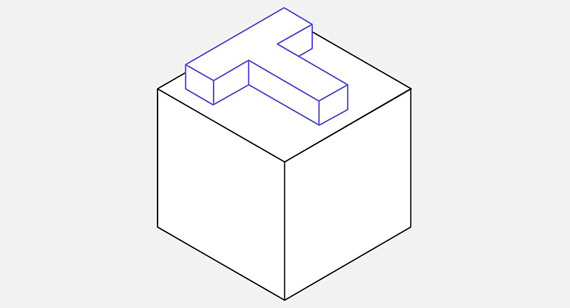
When incorporating text or lettering into CNC machined parts, it is important to select appropriate font styles and sizes to ensure clarity and machinability. Sans-serif fonts, such as Arial or Helvetica, are recommended for their simplicity and ease of machining. Avoid using overly decorative or intricate fonts, which can complicate the machining process and reduce legibility.
Additionally, maintaining a consistent font size, typically no smaller than 2mm in height, ensures that the text is clear and legible on the final part. Consistent font sizes facilitate accurate machining and enhance the professional appearance of the part.
Furthermore, considering the orientation and placement of text features to facilitate easier machining and avoid areas prone to tool interference or deflection is essential. By following these recommendations, designers can create machined parts with clear and functional text features that meet both aesthetic and practical requirements.
Designing parts for CNC machining requires a strategic approach that balances design complexity with manufacturability. By following best practices, designers can create components that are not only functional and aesthetically pleasing but also cost-effective and efficient to produce. The following ten tips offer valuable insights into optimizing your CNC machining designs, ensuring that your parts are manufacturable, reliable, and of high quality.
1. Avoid Thin Walls
Thin walls can pose significant challenges in CNC machining, as they are more susceptible to deformation, vibration, and tool deflection. To maintain part integrity and ensure machinability, it is advisable to avoid excessively thin walls in your designs.
Instead, incorporate reinforcement features such as ribs or gussets to enhance the structural stability of thin sections. By distributing stress more evenly and providing additional support, these features help prevent warping and maintain the desired dimensions and tolerances.
Additionally, maintaining a consistent wall thickness throughout the part facilitates uniform machining and reduces the risk of localized weaknesses. This approach not only improves the part's durability but also enhances the efficiency and quality of the CNC machining process.
2. Avoid Designing Features That Cannot Be CNC Machined
CNC machining offers a high degree of precision and flexibility, but there are still limitations to what can be achieved. Designing features that are too intricate, overly small, or excessively deep can make them difficult or impossible to machine effectively.
To ensure manufacturability, avoid designing features such as undercuts, extremely small radii, or overly complex internal geometries unless you have access to advanced multi-axis CNC machines and specialized tooling. Simplifying your designs by eliminating unnecessary complexities and focusing on features that align with standard machining capabilities can significantly enhance the efficiency and cost-effectiveness of the manufacturing process.
By designing within the practical limitations of CNC machining, you can prevent production delays, reduce tooling costs, and ensure that your parts meet the desired quality standards.
3. Avoid Overuse of Tight Tolerances
While tight tolerances can enhance the precision and functionality of a part, over-specifying them can lead to increased production costs, longer machining times, and higher tool wear. It is important to balance the need for precision with the practical considerations of the CNC machining process.
Only apply tight tolerances to critical dimensions that directly impact the part's functionality or assembly. For non-critical dimensions, using standard or slightly looser tolerances can streamline the machining process, reduce production time, and lower costs.
Additionally, clear communication of tolerance requirements with the CNC machining factory ensures that both parties understand the importance of specific dimensions, facilitating more accurate and efficient machining.
By judiciously applying tolerances, designers can achieve the desired balance between part quality and manufacturability, optimizing both performance and cost-efficiency.
4. Avoid Unnecessary Aesthetic Features
While aesthetic features can enhance the visual appeal of a part, they should not compromise its manufacturability or functionality. Incorporating overly decorative elements, such as intricate engravings, complex curves, or unnecessary surface textures, can complicate the CNC machining process, leading to longer production times and higher costs.
To maintain efficiency and cost-effectiveness, focus on essential aesthetic features that add value to the part without introducing excessive complexity. Simplifying design elements and avoiding non-functional decorative features can streamline the machining process, reduce tool wear, and ensure consistent part quality.
By prioritizing functionality and manufacturability over unnecessary aesthetics, designers can create parts that are both visually appealing and easy to produce, optimizing both design and manufacturing outcomes.
5. Design Cavities with Exact Depth-to-Width Ratios
When designing cavities, such as pockets or recesses, maintaining an optimal depth-to-width ratio is essential for machinability and part integrity. As previously mentioned, the depth of a cavity should generally not exceed four times its width.
This ratio ensures that the cutting tools can access and machine the cavity efficiently without excessive tool wear or part deformation. By adhering to exact depth-to-width ratios, designers can facilitate effective chip evacuation, minimize machining time, and maintain the desired surface finish and dimensional accuracy.
Additionally, considering the angle and orientation of cavities in relation to the machine's axes can further enhance machinability and part quality. By carefully designing cavities with appropriate ratios and orientations, designers can optimize the CNC machining process and achieve high-quality, manufacturable parts.
6. Add Radius When Designing Inside Vertical Edges
Sharp inside vertical edges can pose significant challenges in CNC machining, leading to tool deflection, increased wear, and potential surface imperfections. To enhance machinability and part durability, it is recommended to incorporate radii at all inside vertical edges.
Adding a radius of at least 0.2mm to 0.5mm can significantly improve the accessibility of the cutting tool, reduce stress concentrations, and enhance the overall surface finish of the part.
Moreover, radiused edges facilitate smoother tool paths, minimizing the risk of tool marks and improving the aesthetic quality of the machined part. By consistently applying radii to inside vertical edges, designers can ensure that their parts are both functional and easy to machine, resulting in higher quality and more reliable CNC machined components.
7. Limit Thread Length
Excessively long threads can lead to challenges in CNC machining, as they require deeper tool engagement and can increase tool wear. To ensure efficient machining and maintain part integrity, it is advisable to limit the length of threads to a practical extent.
A general guideline is to limit thread length to no more than three times the thread diameter. For example, for an M6 thread, the maximum recommended thread length would be 18mm. This limitation ensures that threads are sufficiently robust without introducing unnecessary machining complexities or compromising the part's structural strength.
By adhering to recommended thread lengths, designers can facilitate more efficient machining, reduce production time, and enhance the durability and reliability of threaded connections in the final product.
8. Avoid Extremely Small Features
Incorporating extremely small features, such as tiny holes, intricate engravings, or minute surface textures, can pose significant challenges in CNC machining. These features can be difficult to machine accurately, leading to potential errors, increased production time, and higher tooling costs.
To ensure manufacturability and maintain part quality, it is recommended to avoid designing features that are smaller than 1mm to 1.5mm in size, depending on the material and machining parameters. If small features are essential for the part's functionality or aesthetic appeal, consider using specialized micro-tools or alternative manufacturing processes, such as EDM (Electrical Discharge Machining) or additive manufacturing.
Additionally, evaluating the necessity of small features and exploring design alternatives can help simplify the machining process, reduce production costs, and enhance part reliability.
9. Design Standard-Sized Holes
Standardizing hole sizes in your CNC machining designs can significantly streamline the manufacturing process and reduce costs. Utilizing standard drill bit sizes, such as 3mm, 4mm, 5mm, etc., allows for the use of readily available tools, minimizing the need for custom tooling and reducing production lead times.
Standard-sized holes are also easier to machine consistently, ensuring uniformity across multiple parts and reducing the likelihood of machining errors or variations in dimensions. Moreover, standard sizes facilitate easier part assembly and compatibility with standard fasteners and components, enhancing the overall functionality and usability of the machined parts.
By designing with standard-sized holes, you can optimize machinability, reduce tooling costs, and ensure that your parts are compatible with commonly available components, leading to more efficient and cost-effective production processes.
10. Avoid Unnecessary Text and Letters
While incorporating text and lettering can add valuable information or branding to CNC machined parts, it is important to avoid overusing these features to prevent complications in the machining process. Excessive text or overly elaborate lettering can complicate tool paths, increase machining time, and lead to surface imperfections.
To maintain efficiency and part quality, limit the use of text and letters to essential information, such as part numbers, logos, or identification markings. Ensure that the size and font of the text are appropriate for machining, maintaining legibility without introducing excessive complexity.
Additionally, consider the orientation and placement of text features to facilitate easier machining and avoid areas prone to tool interference or deflection. By strategically incorporating text and letters, designers can enhance the functionality and branding of their parts without compromising manufacturability or increasing production costs.
Designing parts for CNC machining requires a blend of creativity, technical knowledge, and strategic planning. Without adhering to best practices, designers may encounter challenges such as increased production costs, longer machining times, and compromised part quality. These issues can lead to project delays, budget overruns, and diminished product performance, ultimately impacting the success of your manufacturing endeavors. To navigate these complexities and ensure the efficient production of high-quality CNC machined parts, it is essential to implement proven design strategies that align with CNC machining capabilities.
A Comprehensive Approach to CNC Machining Design
Implementing best practices in CNC machining design involves understanding the nuances of different machining processes, selecting appropriate tools, and optimizing part geometries for manufacturability. By focusing on design principles that facilitate ease of machining, designers can enhance production efficiency, reduce costs, and achieve superior part quality. This approach not only streamlines the manufacturing process but also ensures that the final product meets both functional and aesthetic requirements.
Transitioning to Essential Design Strategies
To master the art of designing for CNC machining, it is crucial to delve into specific strategies tailored to various machining techniques such as milling, turning, and drilling. This guide will explore best practices for each of these processes, providing actionable insights and recommendations to optimize your CNC machining designs. By following these guidelines, designers can create parts that are not only functional and aesthetically pleasing but also cost-effective and efficient to produce.
1. Designing for CNC Milling
CNC milling is a subtractive manufacturing process that uses rotary cutters to remove material from a workpiece, shaping it into the desired geometry. Unlike other machining processes, milling can create complex shapes, including intricate details and precise contours, making it a versatile choice for a wide range of industries. CNC milling machines operate based on computer-generated instructions, allowing for high precision and repeatability in producing complex parts.
The milling process involves various operations such as drilling, slotting, and contouring, which can be performed using different types of milling machines, including 3-axis, 4-axis, and 5-axis CNC mills. The choice of machine and milling technique depends on the complexity of the part, the material being machined, and the desired finish quality. CNC milling is widely used in industries like aerospace, automotive, medical devices, and consumer electronics due to its ability to produce high-precision components with intricate geometries.
Understanding the capabilities and limitations of CNC milling is fundamental to effective parts design. By leveraging the flexibility of milling operations, designers can create parts that meet stringent performance requirements while optimizing material usage and production efficiency.
1.1 Common Cutting Tools
Selecting the appropriate cutting tools is paramount in CNC milling design, as the right tool can significantly influence machining efficiency, surface finish quality, and tool longevity. Common cutting tools used in CNC milling include:
Choosing the right cutting tool involves considering factors such as the material being machined, the desired surface finish, and the specific milling operation. Proper tool selection enhances machining performance, reduces tool wear, and ensures consistent part quality, making it a critical aspect of CNC milling design.
1.2 Avoid Sharp Internal Corners
Sharp internal corners can pose significant challenges in CNC milling, leading to increased tool wear, longer machining times, and potential part deformation. When a milling tool encounters a sharp corner, it must change direction abruptly, which can cause excessive stress on the tool and the workpiece. This abrupt change can lead to tool breakage, surface imperfections, and reduced part integrity.
To mitigate these issues, it is recommended to incorporate a minimum radius at all internal corners. A fillet radius of at least 0.2mm to 0.5mm is generally advisable, depending on the material and machining parameters. This radius allows the cutting tool to transition smoothly between surfaces, reducing stress concentrations and enhancing tool life. Additionally, rounded corners improve the overall surface finish by minimizing tool marks and surface irregularities.
Incorporating radiused internal corners not only facilitates easier machining but also enhances the structural integrity and aesthetic appeal of the part. This practice ensures that CNC milling operations are more efficient and that the final product meets the desired quality standards without unnecessary complications or costs.
1.3 Avoid Deep Narrow Slots
Deep narrow slots can be challenging to machine using CNC milling due to restricted tool access and difficulties in chip evacuation. When a milling tool attempts to cut a deep narrow slot, it may experience excessive tool deflection, leading to inaccurate dimensions and poor surface finishes. Additionally, narrow slots can impede the removal of chips, causing clogging and overheating, which further exacerbates tool wear and reduces machining efficiency.
To address these challenges, it is advisable to limit the depth-to-width ratio of slots. A recommended guideline is to maintain a depth-to-width ratio of no more than 3:1. This ratio ensures that the slot can be machined effectively without causing excessive tool deflection or chip accumulation. If deeper slots are necessary for functional or design purposes, consider alternative machining strategies such as:
By avoiding excessively deep narrow slots and implementing these alternative strategies when deeper slots are required, designers can enhance machinability, reduce production costs, and ensure the production of high-quality CNC machined parts.
1.4 Design with Largest Internal Radius Possible
Maximizing the internal radius in CNC milling designs offers several benefits that enhance both manufacturability and part performance. A larger internal radius reduces the stress concentration points within the part, improving its structural integrity and resistance to fatigue. Additionally, a larger radius facilitates smoother tool paths, minimizing the risk of tool deflection and wear during machining operations.
From a machining perspective, larger internal radii allow for the use of more robust cutting tools, which can achieve higher material removal rates without compromising part accuracy or surface finish. This can lead to shorter machining times, increased production efficiency, and lower tooling costs. Moreover, larger radii simplify the machining process, reducing the likelihood of surface imperfections and ensuring a consistent, high-quality finish.
Incorporating the largest feasible internal radii in part designs not only improves machinability but also enhances the overall durability and aesthetic appeal of the final product. This practice aligns with CNC milling best practices by balancing design requirements with practical machining considerations, resulting in parts that are both functional and cost-effective to produce.
1.5 Other Geometries
Beyond avoiding sharp internal corners and deep narrow slots, several other geometric considerations can significantly impact the manufacturability and quality of CNC machined parts. These include:
By thoughtfully addressing these geometric considerations, designers can create CNC machined parts that are not only aesthetically pleasing but also optimized for efficient and cost-effective production. These practices contribute to the overall success of CNC machining projects by ensuring that parts are manufacturable, durable, and meet the desired quality standards.
CNC turning is a precision machining process that involves rotating a workpiece against a cutting tool to remove material and shape the part. Unlike milling, which primarily involves lateral cutting, turning focuses on axial cutting, making it ideal for producing cylindrical and symmetrical parts such as shafts, rods, and pulleys. CNC turning machines, also known as lathes, are equipped with computer-controlled systems that automate the machining process, ensuring high precision, consistency, and repeatability in part production.
The turning process begins with mounting the workpiece onto the machine's spindle, which rotates the part at controlled speeds. A cutting tool is then fed into the workpiece to perform various operations such as facing, turning, threading, and grooving. CNC turning offers several advantages, including the ability to produce parts with tight tolerances, excellent surface finishes, and complex geometries that would be challenging to achieve manually.
Understanding the capabilities of CNC turning is essential for designing parts that leverage the process's strengths while mitigating its limitations. By aligning part designs with CNC turning best practices, designers can optimize manufacturability, reduce production costs, and achieve high-quality outcomes in their CNC machining projects.
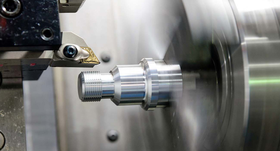
2.2 Avoid Sharp Internal and External Corners
Sharp corners, both internal and external, can significantly complicate CNC turning operations, leading to increased tool wear, longer machining times, and potential part deformation. When a cutting tool encounters a sharp corner, it must change direction abruptly, which can place excessive stress on the tool and the workpiece. This abrupt change can result in tool breakage, surface imperfections, and compromised part integrity.
To mitigate these issues, it is recommended to incorporate a minimum radius at all corners, both internal and external. A fillet radius of at least 0.2mm to 0.5mm is generally advisable, depending on the material and machining parameters. This radius allows the cutting tool to transition smoothly between surfaces, reducing stress concentrations and enhancing tool life. Additionally, rounded corners improve the overall surface finish by minimizing tool marks and surface irregularities.
Incorporating radiused corners not only facilitates easier machining but also enhances the structural integrity and aesthetic appeal of the part. This practice ensures that CNC turning operations are more efficient and that the final product meets the desired quality standards without unnecessary complications or costs.
2.3 Avoid Slender Parts
Designing slender parts for CNC turning can present several challenges, including increased risk of part vibration, tool deflection, and potential breakage during machining. Slender parts are more susceptible to bending and deformation under machining forces, which can lead to inaccurate dimensions and compromised part quality. Additionally, machining slender parts often requires specialized tooling and machining techniques to maintain part stability and prevent deflection.
To address these challenges, it is advisable to minimize the slenderness ratio (length-to-diameter ratio) of turned parts. Maintaining a lower slenderness ratio enhances part rigidity and stability during machining, reducing the risk of vibration and deflection. If slender parts are necessary for functional or design purposes, consider incorporating the following strategies:
By avoiding excessively slender designs or implementing these strategies when slender parts are necessary, designers can enhance the machinability, durability, and overall quality of CNC turned parts, ensuring successful production outcomes.
2.4 Avoid Thin Walls
Thin walls in CNC turned parts can lead to several manufacturing challenges, including increased susceptibility to vibration, part deformation, and tool deflection during machining operations. Thin-walled sections are more prone to bending and vibration under machining forces, which can result in inaccurate dimensions, poor surface finishes, and compromised part integrity. Additionally, thin walls may not provide sufficient support for machining tools, increasing the risk of tool breakage or part damage.
To ensure manufacturability and maintain part integrity, it is recommended to avoid designing parts with excessively thin walls. Instead, incorporate a minimum wall thickness of approximately 1.0mm to 2.0mm, depending on the material and machining parameters. Maintaining adequate wall thickness enhances part rigidity and stability, reducing the risk of deformation and vibration during machining operations.
Additionally, incorporating reinforcing features such as ribs or gussets can provide additional structural support to thin-walled sections, enhancing their rigidity and durability without significantly increasing material usage. This approach allows for the creation of lightweight parts that are both strong and stable, optimizing material efficiency and machining performance.
By avoiding thin walls and implementing reinforcing strategies where necessary, designers can enhance the manufacturability, durability, and quality of CNC turned parts, ensuring that they meet both functional and aesthetic requirements without compromising on performance or manufacturability.
2.5 Feature Symmetry
Symmetrical features in CNC turned parts offer several advantages that enhance both machinability and part performance. Symmetry ensures balanced tool engagement, reducing the risk of vibration and tool deflection during machining operations. Balanced tool engagement leads to smoother tool paths, improved surface finish quality, and increased machining efficiency.
Moreover, symmetrical features facilitate easier part alignment and setup on the CNC turning machine, streamlining the machining process and reducing the likelihood of errors or inconsistencies. Symmetrical designs also contribute to uniform material distribution, enhancing the part's structural integrity and resistance to stress concentrations.
From a design perspective, incorporating symmetry simplifies the creation of complex geometries, allowing for more precise and consistent machining operations. Symmetrical parts are easier to inspect and maintain, ensuring that they meet stringent dimensional and tolerance requirements.
By designing parts with symmetrical features, designers can optimize CNC turning operations, enhancing part quality, reducing production costs, and ensuring efficient and reliable manufacturing processes. Symmetry not only improves machinability but also contributes to the overall aesthetic appeal and functional performance of CNC machined turned parts.
Drilling is a fundamental CNC machining operation that involves creating holes in a workpiece using a rotating cutting tool known as a drill bit. This process is essential for various applications, including assembly, fastening, and fluid transfer in parts across different industries such as automotive, aerospace, electronics, and construction. CNC drilling allows for precise hole placement, consistent diameters, and accurate depths, ensuring that holes meet the specific requirements of the part's design and functionality.
The drilling process begins with mounting the workpiece onto the CNC machine's spindle, which rotates the part at controlled speeds. The drill bit is then fed into the workpiece, cutting through the material to create the desired hole. CNC drilling offers several advantages, including high precision, repeatability, and the ability to automate multiple drilling operations in a single setup, enhancing production efficiency and reducing labor costs.
Understanding the intricacies of CNC drilling is crucial for designing parts that can be machined effectively and accurately. By aligning part designs with CNC drilling best practices, designers can ensure that holes are manufactured to precise specifications, enhancing part functionality and assembly reliability.
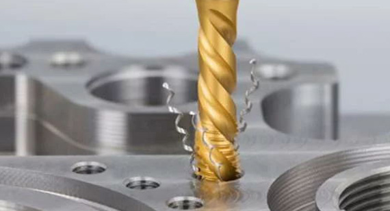
In CNC drilling, holes can be classified into two main types: through holes and blind holes. Each type serves distinct purposes and requires specific design considerations to ensure machinability and functionality.
Designing for through holes is generally simpler and more cost-effective due to the ease of machining and reduced tool wear. In contrast, blind holes require meticulous design and machining precision to achieve the desired depth and diameter without compromising part integrity or functionality. Understanding the differences between through and blind holes is essential for effective
CNC drilling design, ensuring that holes are manufactured accurately and meet the specific requirements of their intended applications.
When Creating Designs for CNC Drilling, Consider the Following Recommendations:
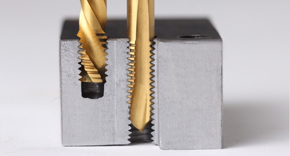
3.1 Proper Hole Depth
Specifying the correct hole depth is critical in CNC drilling to ensure that blind holes meet their functional requirements without causing machining issues. Improper hole depth can lead to incomplete drilling, over-drilling, or under-drilling, resulting in part defects and compromised functionality. To achieve precise hole depths, consider the following recommendations:
By adhering to these recommendations, designers can ensure that hole depths are accurately achieved, enhancing part functionality and reducing the risk of machining errors.
3.2 Avoid Partial Holes
Partial holes, where the drill bit does not fully penetrate the material or stops prematurely, can lead to incomplete machining and compromised part functionality. Partial holes can result from factors such as incorrect machine programming, tool wear, or inadequate machining parameters. To avoid the occurrence of partial holes, consider the following strategies:
By avoiding partial holes, designers can ensure that CNC drilled parts meet their functional requirements and maintain high-quality standards, enhancing overall part reliability and performance.
3.3 Keep the Drill Axis Perpendicular to Surface
Maintaining a perpendicular drill axis to the workpiece surface is essential for achieving accurate and consistent hole dimensions. Deviations from perpendicularity can result in angled holes, uneven diameters, and compromised part functionality. To ensure that the drill axis remains perpendicular during CNC drilling, consider the following recommendations:
By keeping the drill axis perpendicular to the workpiece surface, designers can achieve consistent hole dimensions, enhance part functionality, and maintain high-quality machining standards.
3.4 Avoid Drilling Through Cavities
Drilling through cavities or internal features in a part can complicate the machining process, leading to issues such as chip clogging, tool deflection, and compromised hole accuracy. When a drill bit enters a cavity during drilling operations, it may encounter restricted chip evacuation paths, causing chips to accumulate and interfere with the drilling process. Additionally, the presence of cavities can alter the material flow dynamics, increasing the risk of tool deflection and uneven hole dimensions.
To avoid these complications, it is advisable to design parts in a way that prevents drill bits from entering cavities during drilling operations. Consider the following strategies:
By avoiding drilling through cavities, designers can enhance the machinability of parts, reduce the risk of machining errors, and ensure that holes are accurately drilled to meet functional requirements.
3.5 Use Standard Drill Bit Sizes
Utilizing standard drill bit sizes in CNC drilling designs offers several advantages, including ease of machining, reduced tooling costs, and improved part consistency. Standard drill bit sizes are readily available and commonly used in CNC machining operations, facilitating efficient machining and reducing the need for specialized tooling. To maximize the benefits of using standard drill bit sizes, consider the following recommendations:
By designing parts with standard drill bit sizes, designers can enhance machinability, reduce production costs, and ensure consistent hole dimensions, contributing to efficient and cost-effective CNC drilling operations.
Threaded holes are integral components in many CNC machined parts, serving as attachment points for fasteners, inserts, and other components. Designing threaded holes requires careful consideration to ensure that they are accurately machined, robust, and functional. Key considerations for designing threaded holes include:
By thoughtfully designing threaded holes with these considerations in mind, designers can create robust and functional attachment points that enhance part assembly, reliability, and overall performance.
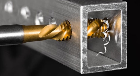
Custom Holes
In certain applications, standard through or blind holes may not suffice, necessitating the creation of custom hole geometries to meet specific functional or design requirements. Custom holes can include features such as counterbores, countersinks, tapered holes, or complex internal profiles. Designing custom holes for CNC machining involves the following considerations:
By incorporating these considerations, designers can effectively create custom hole geometries that meet specific application requirements while ensuring manufacturability and high-quality outcomes in CNC machining operations.
Avoid Deep Hits
Deep hits refer to the practice of drilling or milling holes that extend too deeply into the workpiece, exceeding the recommended depth-to-diameter ratios. Deep hits can lead to several machining challenges, including increased tool wear, longer machining times, and compromised hole accuracy. Additionally, deep hits can cause excessive stress on cutting tools, leading to tool breakage or part deformation.
To avoid deep hits in CNC drilling designs, consider the following recommendations:
By avoiding deep hits and implementing these strategies when deeper holes are necessary, designers can enhance machinability, reduce production costs, and ensure the production of high-quality CNC machined parts that meet functional and design requirements.
By adhering to these best practices, designers can create CNC machined parts that are not only functional and aesthetically pleasing but also optimized for manufacturability, cost-efficiency, and high-quality outcomes. Implementing these strategies ensures that CNC machining projects are executed smoothly, with reduced risk of errors, enhanced part integrity, and improved production efficiency, ultimately contributing to the success of your manufacturing endeavors.
Advanced design strategies can further optimize CNC machining processes, enhancing efficiency, reducing costs, and improving part quality. By implementing these advanced tips, designers can push the boundaries of CNC machining, achieving higher precision and functionality in their machined parts. The following tips cover creating simple setups, managing harder materials, handling non-planar and draft surfaces, minimizing operations, tool changes, workholding setups, fillet vs. chamfer, and tolerances and GD&T (Geometric Dimensioning and Tolerancing).
Create Simple Setups
Simplifying CNC machine setups can significantly reduce production time, tooling costs, and the risk of machining errors. Simple setups involve designing parts that require minimal tool changes, are easily aligned on the machine, and can be machined in a single setup whenever possible.
To create simple setups, consider the following practices:
By creating simple setups, designers can enhance machining efficiency, reduce production costs, and improve overall part quality, ensuring that CNC machining operations are streamlined and cost-effective.
Harder Materials = Longer Machine Run Times
Machining harder materials requires more time and effort compared to softer materials due to increased tool wear, higher machining forces, and the need for slower cutting speeds. Designers should be aware of the impact of material hardness on CNC machining processes and design parts accordingly to optimize production efficiency and costs.
Consider the following strategies when designing for harder materials:
By accounting for the challenges of machining harder materials, designers can create parts that are both functional and cost-effective, ensuring that CNC machining operations are optimized for the chosen material.
Non-Planar and Draft Surfaces Increase Costs
Non-planar surfaces and draft angles add complexity to CNC machining operations, increasing production costs and machining time. Designing parts with non-planar features or steep draft angles can require additional machining steps, specialized tools, and longer machining cycles, contributing to higher production costs and longer lead times.
To manage the costs associated with non-planar and draft surfaces, consider the following recommendations:
By designing with consideration for surface geometry, designers can balance aesthetic and functional requirements with machinability, ensuring that parts are cost-effective and manufacturable within desired timeframes.
Minimize Operations
Reducing the number of machining operations required to produce a part can lead to significant cost savings and increased production efficiency. Each additional operation introduces potential sources of error, increases tool wear, and extends machining time, contributing to higher production costs and longer lead times.
To minimize machining operations, designers should:
By minimizing machining operations, designers can enhance production efficiency, reduce tooling costs, and ensure that parts are produced consistently and accurately, contributing to overall cost-effectiveness and quality in CNC machining processes.
1. Tool Changes
Frequent tool changes can significantly impact production efficiency and costs, as each change requires time and resources for tool retrieval, alignment, and setup. To reduce the number of tool changes, designers can:
By minimizing tool changes, CNC machining processes become more streamlined, reducing production time, lowering tool wear, and enhancing overall machining efficiency.
2. Workholding Setups
Workholding setups secure the part in place during machining, preventing movement and ensuring accurate machining. Each additional workholding setup introduces time and complexity to the machining process, increasing production costs and lead times.
To minimize workholding setups, designers can:
By minimizing workholding setups, designers can streamline the machining process, reducing production time, lowering costs, and enhancing overall part quality.
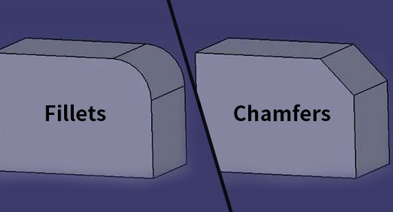
Fillets and chamfers are commonly used features in CNC machining designs, providing aesthetic and functional benefits. However, they differ in their applications and machining considerations.
Fillet: A fillet is a rounded internal corner that smoothens the transition between two intersecting surfaces. Fillets reduce stress concentrations, enhance part durability, and improve surface finish quality. In CNC machining, fillets can be easier to machine with ball nose tools, providing a smooth and consistent radius that enhances machinability.
Chamfer: A chamfer is an angled or beveled edge applied to the external corner of a part. Chamfers facilitate easier part assembly, provide clearance for fasteners, and enhance the overall aesthetic appearance. Chamfers are typically machined using flat end mills or chamfering tools, allowing for precise and clean angled cuts.
When designing for CNC machining, it is important to choose between fillets and chamfers based on the part's functional and aesthetic requirements. Incorporating fillets or chamfers appropriately can enhance the part's machinability, durability, and visual appeal, contributing to a high-quality final product.
Geometric Dimensioning and Tolerancing (GD&T) is a system used in engineering drawings to specify the allowable variations in part dimensions and geometries. GD&T provides a clear and comprehensive method for defining the required tolerances, ensuring that parts are manufactured to precise specifications and function correctly within assemblies.
When designing CNC machining parts, incorporating GD&T principles helps in:
By leveraging GD&T in CNC machining designs, designers can achieve high precision, consistency, and reliability in the final machined parts, ensuring that they meet both functional and quality requirements.
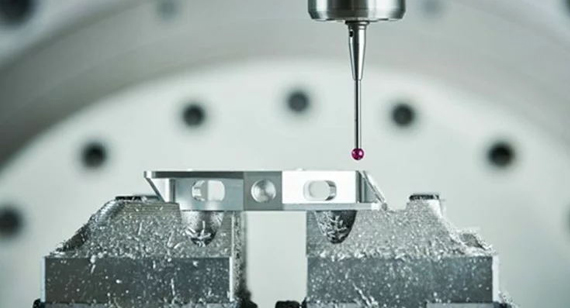
Proper CNC machine setup and part positioning are critical factors that influence the efficiency, accuracy, and quality of CNC machining operations. Thoughtful consideration of machine setups and part orientation ensures that machining processes are optimized, reducing production time and costs while enhancing part precision and surface finish. This section explores the importance of machine setups and part positioning, the benefits of minimizing setups, and the advantages of machining multiple features in a single setup.
When Designing, It Is Important to Consider Machine Setups for Two Reasons:
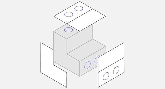
1. The Total Number of Machine Setups Affects Costs
Each machine setup involves time and resources, including tool changes, alignment adjustments, and fixture modifications. The more setups required for a part, the higher the production costs and longer the lead times. By designing parts that can be machined in fewer setups, designers can significantly reduce production costs and enhance manufacturing efficiency.
2. Machining Two Features in the Same Setup
Designing parts to allow for the machining of multiple features in a single setup can streamline the production process, reducing the need for multiple tool changes and workholding adjustments. This approach enhances machining efficiency, lowers production costs, and ensures greater consistency and accuracy in the final parts.
5-axis CNC machining involves the simultaneous movement of the cutting tool and the workpiece along five different axes, allowing for the creation of highly complex and precise geometries that are difficult or impossible to achieve with 3-axis machining. This advanced machining technique offers several advantages, including:
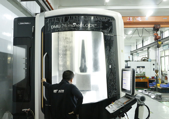
However, 5-axis CNC machining also presents challenges, such as higher machine costs, increased programming complexity, and the need for specialized training and expertise.
Advantages:
Limitations:
By understanding the advantages and limitations of 5-axis CNC machining, designers can determine when this advanced technique is necessary for achieving their part design goals and optimize their manufacturing processes accordingly.
Designing Undercuts for CNC Machining
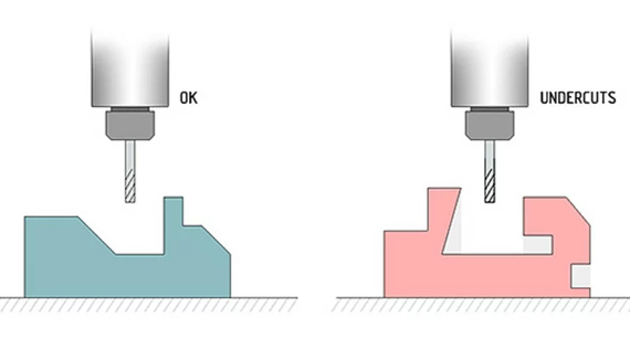
Undercuts in CNC machining refer to recessed or intricate features that extend inward from the main body of the part, creating complex geometries that can be challenging to machine. Designing undercuts requires careful consideration of tool access, machining strategies, and part integrity to ensure successful production and high-quality outcomes.
Key Considerations in Designing Undercuts:
By addressing these considerations, designers can create CNC machined parts with undercuts that are both functional and manufacturable, ensuring high-quality outcomes and efficient production processes.
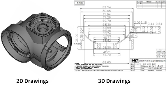
Technical drawings are essential in conveying the detailed specifications and geometries of CNC machined parts, including undercuts. Accurate and comprehensive technical drawings provide clear instructions for CNC machinists, ensuring that parts are manufactured to the desired dimensions, tolerances, and features.
Key Elements of Technical Drawings for CNC Machining:
By creating detailed and accurate technical drawings, designers can facilitate effective communication with CNC machining factories, ensuring that parts are manufactured correctly and efficiently according to the design specifications.
When seeking quotes from CNC machining factories, it is essential to provide clear and comprehensive technical drawings to ensure accurate pricing and production estimates. Properly formatted and detailed drawings enable manufacturers to assess the complexity of the part, determine the required machining processes, and estimate material and production costs accurately.
Steps for Uploading Technical Drawings:
By following these steps and providing comprehensive technical drawings, designers can obtain accurate quotes from CNC machining factories, facilitating informed decision-making and efficient production planning.
Implementing best practices in CNC machining ensures that parts are produced efficiently, accurately, and consistently, meeting both design specifications and quality standards. The following best practices cover key aspects of CNC machining, including tool selection, machine maintenance, quality control, and process optimization.
Tool Selection and Maintenance
Machine Maintenance and Calibration
Quality Control and Inspection
Process Optimization
By adhering to these best practices, CNC machinists and designers can ensure that machined parts are produced with high quality, efficiency, and reliability, meeting the demands of various industries and applications.
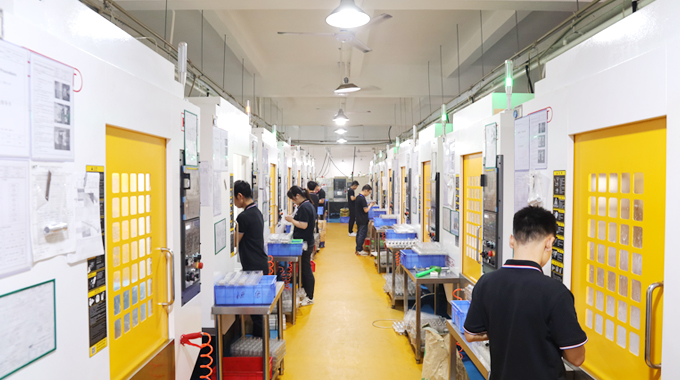
Partnering with a reputable CNC machining factory, such as VMT, can significantly enhance the quality and efficiency of your CNC machining projects. VMT offers a comprehensive range of CNC machining services, including custom CNC machining, CNC prototype machining, and surface treatment services, ensuring that your designed parts are manufactured to the highest standards.
Why Choose VMT?
Contact VMT Today
Whether you require custom CNC machining, prototype machining, or surface treatment services, VMT is your trusted partner for high-quality, cost-effective CNC machined parts. Contact VMT today to discuss your project requirements, receive expert guidance, and obtain accurate quotes, ensuring that your CNC machining designs are brought to life with precision and excellence.
CNC machining parts design is a multifaceted process that requires a thorough understanding of machining principles, design best practices, and the capabilities and limitations of CNC machining technologies. By adhering to fundamental design rules, considering tool geometry and access, managing tolerances effectively, and implementing best practices in machining, designers can create parts that are both functional and manufacturable.
Understanding the intricacies of CNC machining, from milling and turning to drilling and advanced multi-axis operations, empowers designers to optimize their designs for efficiency, cost-effectiveness, and high-quality outcomes. Collaborating with experienced CNC machining factories, such as VMT, further enhances the design-to-production process, ensuring that parts are manufactured with precision, reliability, and excellence.
Whether you are embarking on a new design project, seeking to optimize existing designs, or exploring advanced machining techniques, this complete guide provides the insights and strategies necessary to achieve successful CNC machining outcomes. Embrace these principles and best practices to create high-quality CNC machined parts that meet your functional and aesthetic requirements, driving success in your manufacturing endeavors.
1. What is CNC design?
CNC design refers to the process of creating detailed and precise designs for parts that are intended to be manufactured using CNC (Computer Numerical Control) machining technologies. It involves using CAD (Computer-Aided Design) software to develop the part's geometry, dimensions, and features, which are then translated into CNC machining instructions via CAM (Computer-Aided Manufacturing) software.
2. What software is used to design CNC parts?
Common software used for designing CNC parts includes CAD (Computer-Aided Design) tools like SolidWorks, AutoCAD, and Fusion 360, which are used to create detailed 3D models of parts. CAM (Computer-Aided Manufacturing) software, such as Mastercam, Siemens NX, and Autodesk HSM, is then used to generate the tool paths and machining instructions for CNC machines.
3. What are the criteria for designing CNC machines?
Criteria for designing CNC machines include the desired machining capabilities (e.g., number of axes, precision), material handling and workholding systems, tool selection and accessibility, machine rigidity and stability, software compatibility, and operational efficiency. Additionally, considerations such as ease of maintenance, safety features, and scalability for future production needs are important in CNC machine design.
4. Which design software is best for CNC programming?
The best design software for CNC programming depends on the specific requirements and preferences of the user. Popular options include Mastercam, Siemens NX, Fusion 360, SolidWorks CAM, and CATIA, each offering robust features for tool path generation, simulation, and integration with various CNC machines.
5. Is CNC machining faster than 3D printing?
CNC machining is generally faster than 3D printing for producing parts with high precision and tight tolerances, especially in high-volume production settings. However, 3D printing can be more efficient for creating complex geometries and prototypes without the need for extensive tooling or setup. The speed comparison depends on the part's complexity, material, and production volume.
6. What are the biggest disadvantages of using CNC?
The biggest disadvantages of using CNC machining include the high initial cost of CNC machines, the need for skilled operators and programmers, potential limitations in machining complex geometries without advanced multi-axis machines, and the cost of tooling and maintenance. Additionally, CNC machining may not be cost-effective for low-volume or highly customized parts.
7. What materials are the most difficult for CNC machining?
Materials that are difficult for CNC machining typically include hardened metals (e.g., titanium alloys, Inconel), composites, and materials with high thermal conductivity. These materials can cause increased tool wear, require specialized tooling and machining parameters, and may pose challenges in achieving precise dimensions and surface finishes.
By adhering to the comprehensive principles and strategies outlined in this guide, manufacturers can harness the full potential of industrial design prototyping and CNC machining undercuts to optimize their design processes, reduce costs, and deliver high-quality products that meet market demands and exceed user expectations. Leveraging advanced prototyping techniques, utilizing comprehensive design and testing processes, and avoiding common pitfalls are essential for successful product development and market success. Partnering with experts like VMT can further streamline the prototyping process, ensuring that your CNC machined parts with undercuts are manufactured with precision, quality, and efficiency, paving the way for successful product launches and sustained market presence.
