16 years one-stop China custom CNC machining parts factory

Hey there I’m VMT Sam!
With 25 years of CNC machining experience we are committed to helping clients overcome 10000 complex part-processing challenges all to contribute to a better life through intelligent manufacturing. Contact us now
 58 |
Published by VMT at Nov 16 2026 | Reading Time:About 8 minutes


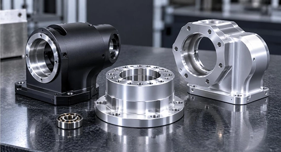
Custom CNC machined robot actuator housings serve as high-rigidity mechanical foundations that directly affect a robot joint’s dynamic accuracy, heat dissipation, and overall service life. Achieving high-quality manufacturing requires attention to the following factors:
Case Study Overview In The End Part: Precision CNC Machining of a 6061 Aluminum High-Speed Micro Motor Housing – Achieving 0.01 mm Concentricity, 8 μm Critical Dimensional Accuracy, and Stable Delivery of 60,000 Units in 35 Days.
Motion type, payload requirements, and thermal and spatial constraints are the primary factors determining the type of robot actuator housing required. Meanwhile, the fit accuracy of internal moving components, heat dissipation efficiency during motor operation, and smooth transmission of joint torque are closely related to the geometric features of CNC machined robot actuator housings.
Types of Robot Actuator Housing Components
Integrated Rotary Actuator Main Housing: Commonly used in collaborative robot arms and integrated joints for humanoid robots. These housings integrate multiple components, including frameless torque motors, harmonic or planetary gear reducers, dual absolute encoders, and servo drive boards.
Servo Motor and Frameless Motor Housings: These housings provide rigid support for the motor stator and rotor bearings. They require high coaxiality between the bearing seats at both ends and the stator bore, typically within 0.015 mm to 0.03 mm.
Harmonic and Cycloidal Gearbox Housings: Designed to accommodate flexsplines, circular splines, cycloidal discs, and cross-roller bearings. These housings typically feature lightweight, thin-wall structures and require tight control of end-face runout and axial perpendicularity, generally within 0.005 mm to 0.01 mm.
Peripheral Motion Components:
Typical Geometric Features of Custom CNC Machined Robot Actuator Housing Components
Robot actuator housings often incorporate multiple demanding geometric constraints, presenting several challenges for CNC machining.
( Note: The following sections will discuss how to address these machining challenges in detail. This section provides an overview of the typical design features and manufacturing requirements. )
CNC machining vs 3D printing + CNC machining vs die casting + CNC machining represent different trade-offs in terms of cost, material selection, production volume, rigidity, and dimensional consistency for custom robot actuator housings:
Table: Manufacturing Processes for Robot Actuator Housings
| Comparison Criteria | Solid CNC Machining | 3D Printing + CNC Finishing | Die Casting + CNC Finishing |
| Primary Application | Preferred for prototyping to medium-volume production (1–2,000 pcs); suitable for high rigidity and tight tolerances | Suitable for highly complex topologies and internal conformal cooling channels | High-volume mass production |
| Mechanical Properties and Rigidity | Best overall (isotropic properties of wrought material, without casting porosity or internal void defects) | Good (may contain residual micropores or exhibit microscopic anisotropy) | Generally lower (internal shrinkage cavities and porosity may occur, reducing impact load resistance) |
| Dimensional Accuracy and Wall Thickness Consistency | Very high (can achieve tolerances of ±0.005 mm to ±0.01 mm) | Depends on CNC finishing; warpage in the printed part may affect fixture datum accuracy | Depends on CNC finishing; draft angles and wall-thickness shrinkage can be significant |
| Material Selection | Widest material selection (various aluminum alloys, copper, titanium alloys, stainless steels, engineering plastics, etc.) | Limited to specific metal powders and resins compatible with 3D printing | Limited to non-ferrous metals (aluminum, zinc, magnesium alloys, etc.) |
| Initial Tooling Cost and Lead Time | No tooling costs. Prototype samples can typically be delivered within 3–7 days after drawing approval | No tooling costs, but printing takes longer and post-processing can be labor-intensive | Requires expensive tooling ($5,000+), with sampling typically taking 4–8 weeks |
| Recommendation | First choice: Recommended for actuator housings requiring structural validation, rapid design iterations, high rigidity, small-to-medium production volumes, high precision, and dimensional stability | Consider when special internal cooling channels or topology-optimized lightweight structures are required | Consider when the design is finalized and annual demand exceeds 10,000 sets |
Note: The actual manufacturing process should be selected in consultation with the manufacturer based on part geometry, material requirements, tolerances, production volume, and overall project costs.
Table: Manufacturing Tolerances and Inspection Standards for CNC Machined Robot Actuator Housings
| Evaluation Metric | Commercial Grade | Precision Grade | Ultra-Precision / Critical Features |
| Bearing Bore Diameter Tolerance | ±0.02 mm (ISO 2768-m) | ±0.01 mm | ±0.005 mm (IT5/IT6 fit) |
| Bearing Seat Coaxiality | 0.03 mm | 0.015 mm | ≤ 0.008 mm |
| End-Face Flatness and Perpendicularity | 0.05 mm | 0.02 mm | ≤ 0.01 mm |
| Seal Groove and Bearing Seat Surface Roughness (Ra) | Ra 1.6 μm (63 μin) | Ra 0.8 μm (32 μin) | Ra 0.4 μm (16 μin) (with precision grinding/lapping) |
| Thread Accuracy | 6H / 2B | 6H (high-precision anti-loosening fit) | 4H5H (aerospace-grade vibration-resistant fit) |
| Inspection and Verification Methods | Calipers, digital height gauges | Optical comparator (2D measurement system), CMM (sampling inspection) | CMM (100% inspection report for critical dimensions) |
When sourcing and evaluating high-precision robot actuator housings, most prototype failures and pilot production delays can be traced to several common geometric tolerance issues. The following sections outline typical geometric defects encountered in CNC machining robot actuator housings and the corresponding solutions.
1. Roundness Distortion and Surface Chatter in Thin-Wall Annular Actuator Housings
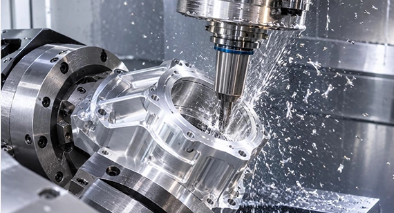
To reduce weight, robot actuator housings often feature wall thicknesses as low as 1.2–1.5 mm. Radial clamping with a standard three-jaw chuck can deform the circular housing into a petal-like shape. During milling, cutting forces can also trigger resonance, resulting in uneven wall thickness or visible chatter marks on the machined surface.
Design Recommendations:
Our Factory's Machining Solutions:
2. Excessive Coaxiality Deviation and Runout Between Bearing Seats and Flange Mounting Faces
Robot actuator housings often have relatively long axial spans. When conventional 3-axis CNC machines are used with multiple reorientations and setups, accumulated repositioning errors can cause the bearing bores at both ends to become misaligned. After assembly, this can directly lead to bearing binding, a sharp increase in no-load motor current, and abnormal wear on the gear reducer tooth surfaces.
3. Warpage and Dimensional Drift Caused by Residual Stress Release After Machining
This issue is particularly common with high-strength aerospace aluminum alloys such as 7075. When more than 70% of the original material is removed to create internal cavities, the internal stress balance of the raw material is disrupted. After the part is removed from the machine and the fixture is released, or even after several days of storage, gradual material movement may occur. As a result, previously acceptable bore diameters and mounting face flatness can drift beyond specified tolerances.
4. Bearing Bore Shrinkage and Thread Seizure After Anodizing
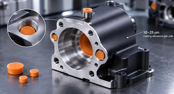
Anodizing is a common surface treatment for robot actuator housings. It improves corrosion and wear resistance, but the coating thickness must be accounted for during machining.
A typical example is Type III hard anodizing, which can add 10–25 μm of coating thickness per side. If no coating allowance is included during CNC machining, the bearing seat bore may become undersized after anodizing, preventing proper bearing press-fit assembly. Similarly, coating buildup inside small threaded holes can cause fasteners to bind or seize during installation.
Tips for drawings:
Clearly specify on the engineering drawing whether dimensional tolerances apply to the pre-plating or post-plating dimensions.
How Our Factory Handles This:
Summary Recommendations: For conventional lightweight actuator housings, 6061 is generally the first choice because it balances heat dissipation, machining efficiency, and cost. For structures exposed to high loads, impact, and demanding fatigue conditions, 7075 is worth considering. For medical, marine, and other specialized environments requiring a higher strength-to-weight ratio and corrosion resistance, Ti-6Al-4V may be evaluated.
When designing lightweight robot actuator housings, material selection should not be based on strength alone. Structural rigidity, heat dissipation, fatigue life, machining costs, and surface treatment requirements must also be considered. 6061, 7075, and Ti-6Al-4V are three representative materials suited to conventional lightweight applications, high-load structures, and demanding operating environments, respectively.
6061 (Cost-Effective Performance and Heat Dissipation)
7075-T6 (Preferred for High-Stress and Impact-Loaded Applications)
Ti-6Al-4V / Grade 5 Titanium (High Strength-to-Weight Ratio and Corrosion Resistance)
Recommendations: SUS304 is suitable for general humid environments and routine cleaning conditions. When exposed to chlorides, salt spray, or frequent chemical cleaning, SUS316 or SUS316L should be evaluated first. For wear-resistant transmission components operating in seawater or structures with specific spark-resistance requirements, naval brass may also be considered.
When robots need to operate for extended periods in humid, salt-spray, chemical-cleaning, or seawater environments, aluminum alloys may not always be the most suitable material choice:
SUS304 (General-Purpose Corrosion-Resistant Material)
SUS316 / 316L (For Pitting and Chemical Corrosion Resistance)
Naval Brass (C46400) for Supperior Spark-Resistance
Surface treatments also affect the wear resistance, corrosion resistance, dimensional accuracy, and electrical properties of robot actuator housings. In some cases, different surface treatments need to be selected for different areas according to their functional requirements, rather than applying a uniform treatment to the entire component.
Type II Anodizing (Clear / Color Anodizing)
Type III Hardcoat Anodizing
Passivation (For Stainless Steel)
Electroless Nickel Plating
Micro-Arc Oxidation (MAO / PEO, for Aluminum Alloys and Certain Titanium Alloys)
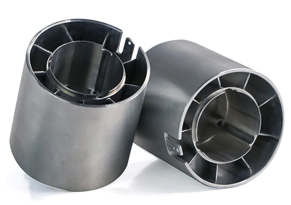
A high-speed micro motor project approached us to address the precision machining and volume production challenges of a 6061 aluminum motor housing. Designed for a high-speed rotating assembly, the component required tight geometric control between multiple critical machined dimensions and rotational features. Several critical dimensions had to be maintained within 8 μm, with a concentricity requirement of 0.01 mm. Meanwhile, the thinnest section of the housing was only 1 mm thick. Beyond meeting strict drawing tolerances, the customer also needed a reliable manufacturing process capable of delivering a total order quantity of 60,000 units.
Challenges:
The main challenges involved thin-wall deformation, concentricity control, and batch-to-batch consistency.
Our Factory’s Solutions:
1. Optimized Manufacturing Route: Based on the component geometry and production volume, our engineering team adopted a near-net-shape die-cast blank combined with precision CNC machining. This approach preserved sufficient machining allowance on critical features while minimizing unnecessary material removal and reducing overall manufacturing costs.
2. Optimized CNC Machining Process: Our engineering team conducted 10 days of machining trials and process adjustments, focusing on optimizing the clamping method and cutting parameters for thin-wall sections. The goal was to minimize deformation caused by uneven machining forces.
3. Precision Control of Rotational Features: We applied targeted precision machining and dimensional verification to critical rotating mating features, with particular attention to maintaining the geometric relationship between multiple concentric features. Through repeated process validation, we gradually established a stable production workflow suited to the component geometry and volume requirements.
Final Results:
Following 10 days of process trials and validation, our on-demand manufacturing facility completed the initial batch, which was approved by the customer. The critical machined dimensions (±8 μm) and concentricity (±0.01 mm) met the project requirements. The validated machining process also provided a stable foundation for subsequent volume production.
Ultimately, our factory completed the production and delivery of all 60,000 units within 35 days, meeting both the precision machining requirements and the project's delivery schedule.
The design and manufacturing of custom robot actuator housings and components require balancing multiple factors, including structural rigidity, lightweight construction and heat dissipation, micron-level coaxiality tolerances, and mass-production costs. Every detail affects the service life and operating performance of actuator housings and components, including smooth, quiet operation. These details range from material selection and stress-relief strategies to control deformation, thin-wall machining and vibration reduction, five-axis single-setup machining to minimize cumulative tolerance errors, and surface treatment with adequate coating thickness allowances. As demonstrated in our high-speed motor housing case study, managing these manufacturing complexities requires an integrated approach that combines thorough DFM feedback, custom fixturing, and rigorous CMM inspection to achieve consistent quality across production batches.
Are you facing challenges with tight tolerances, demanding coaxiality requirements, thin-wall deformation, or material and surface treatment selection? Contact our manufacturing team for a free, comprehensive DFM review and fast quotation. We can help accelerate your project from prototype validation to mass production. [We support 2D Drawings (PDF files), 3D Drawings (IGS/STP/STEP files)].
Send your 2D drawings, 3D CAD models, material, bearing and reducer interfaces, datum requirements, critical tolerances, wall thickness, surface treatment, prototype quantity and production quantity. VMT will review DFM, process selection, thin-wall deformation, coaxiality control, coating allowances, inspection and quotation requirements.
All information and uploaded files are secure and confidential.
1 Tell us what you need
2 Get solution & quote
3 Approve production
Email: inquiry@vimetal.com.cn
Why Is CNC Machining Preferred Over Direct 3D Printing for Precision Robotic Parts?
CNC machining uses dense, isotropic wrought metal stock, such as 6061-T651 or 7075-T6 aluminum, to produce components capable of withstanding the high-frequency start-stop cycles and sudden impact torques experienced by robot joints. CNC machining can also achieve bearing fit tolerances as tight as ±0.005 mm and provide excellent heat-transfer surfaces for motors. These capabilities are difficult to consistently replicate with metal or plastic 3D printing, which may introduce microscopic porosity and dimensional warpage.
What Is the Difference Between an Actuator Housing, Casing, and Enclosure?
In engineering and procurement, these three terms are often used interchangeably, but they have different functional focuses.
An actuator housing typically refers to the primary load-bearing structure, incorporating precision bearing seats, motor stator locating bores, and gearbox mounting datums.
By comparison, casing and enclosure generally refer to the outer protective structure, with a greater emphasis on dust and water sealing (such as IP67 protection), cable routing and shielding, and thermal protection.
What Factors Affect the Cost of Custom CNC Machined Robot Actuator Housings?
The overall cost is primarily determined by several factors:
How Can Thread Stripping and Loosening Be Prevented at Gearbox and Motor Mounting Interfaces?
For aluminum actuator housings exposed to high-frequency vibration, steel helical inserts (Helicoil / Thread Inserts) are recommended when mounting bolts need to be repeatedly removed and reinstalled or must withstand high shear loads. The design should include suitable insert installation holes.
Alternatively, form tapping (roll tapping) can be used instead of conventional cutting taps during machining. This can improve the tensile strength and fatigue resistance of aluminum internal threads by more than 30%.
Why Is Coaxiality Important for Robot Joint Housing Machining?
Coaxiality between bearing seats and other rotating features directly affects shaft alignment, bearing operation, and transmission performance. Excessive deviation can cause bearing binding, uneven shaft loading, increased motor current, and premature gear wear.
What Should You Consider When Selecting a CNC Machining Manufacturer for Robot Actuator Components?
Evaluate the manufacturer's ability to control bearing bore tolerances, coaxiality, thin-wall deformation, and material stress. Also consider custom fixture development, CMM inspection capabilities, surface treatment coordination, and the ability to maintain dimensional consistency during batch production.
The technical information and manufacturing advice shared on the machining-custom.com website are for general guidance only. While we strive for accuracy, machining-custom.com does not guarantee that the processes, tolerances, or material properties mentioned are applicable to every specific project. Any reliance you place on such information is strictly at your own risk. It is the buyer's responsibility to provide definitive engineering specifications for any production orders. Final specifications and service terms shall be subject to the formal contract or quotation confirmed by both parties.


 +86 15099911516



 Read more