16 years one-stop China custom CNC machining parts factory

Hey there I’m VMT Sam!
With 25 years of CNC machining experience we are committed to helping clients overcome 10000 complex part-processing challenges all to contribute to a better life through intelligent manufacturing. Contact us now
 61 |
Published by VMT at Nov 16 2026 | Reading Time:About 8 minutes


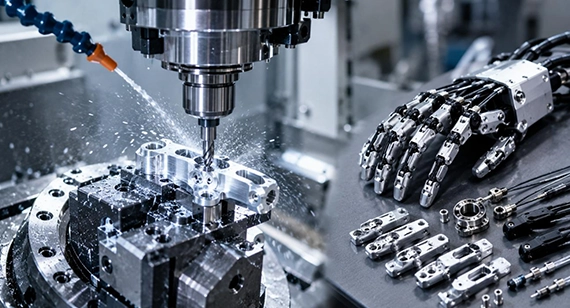
Successful CNC manufacturing of robotic dexterous finger parts depends on controlling miniature geometry, thin-wall deformation, joint alignment, tendon-routing surface quality, and coating-related dimensional changes as one integrated process. For high-precision finger links, joint housings, hinge interfaces, and tendon components, simultaneous 5-axis machining, micro-tool control, low-force custom fixturing, GD&T-based inspection, and reliable micro-burr removal are often more important than machine accuracy alone. When these factors are planned during the DFM stage, manufacturers can reduce joint binding, cable wear, thin-wall distortion, assembly variation, and costly prototype rework.
Manufacturing CNC-machined parts for robotic dexterous fingers presents several key challenges: ultra-thin-wall structures designed to reduce dynamic inertia, micron-level coaxiality across multiple linkage hinges (ensuring that several bores share the same axis), complex contoured channels for tendon routing (the fine cables that actuate finger movement), and intricate cavity geometries packed into spaces no larger than a fingernail.
Robotic dexterous fingers are among the most sophisticated subsystems in advanced robotics. To replicate human-like joint articulation, tactile sensitivity, and high repeatability, these end effectors require exceptionally precise mechanical integration. This article examines the key CNC components used in robotic dexterous fingers, covering five-axis micro-machining strategies, GD&T tolerance control, and a concise supplier selection checklist for coating tolerance control, etc.
The end case study shows how our manufacturing factory process 7075-T6 aluminum dexterous hand integrated proximal phalanx and transmission base component, achieving thin-walled 0.55 mm resonance-free vibration-free surfaces and no warping, as well as a coaxiality of ≤ 0.006 mm between the bearing holes in the end ear mounts.
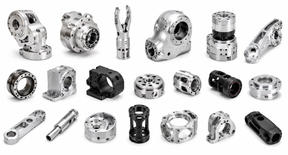
A typical robotic dexterous finger has three to four degrees of freedom (DoF), corresponding to the proximal, intermediate, and distal phalanges. Within this compact space, various structural components, housings, and transmission parts rely heavily on precision multi-axis CNC machining.
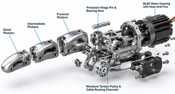
CNC Machined Finger Links / Phalanges (Proximal, Intermediate, and Distal)
CNC Precision Machined Finger Joint Housings
Precision Machined Tendon Pulleys and Cable Guide Components
Custom Machined Hinge Pins and Bearing Seats
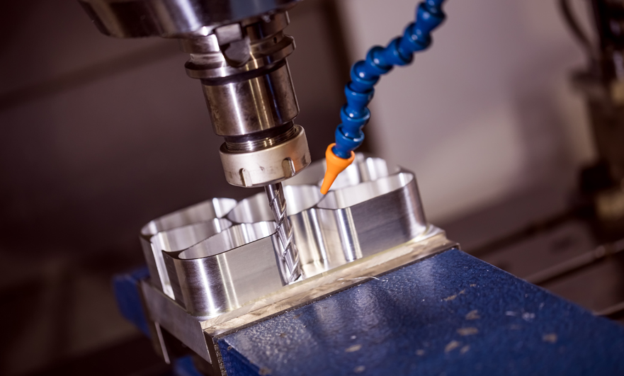
CNC machining robotic dexterous finger parts involves removing material from solid bars or plate stock along specific toolpaths using cutting tools of various diameters on CNC machine tools, gradually forming the required finger component geometry. These parts are typically small and require extremely high dimensional accuracy and coaxiality.
The following are the key manufacturing challenges encountered when CNC machining these precision robotic finger components.
1. Miniature Features and Complex Geometries
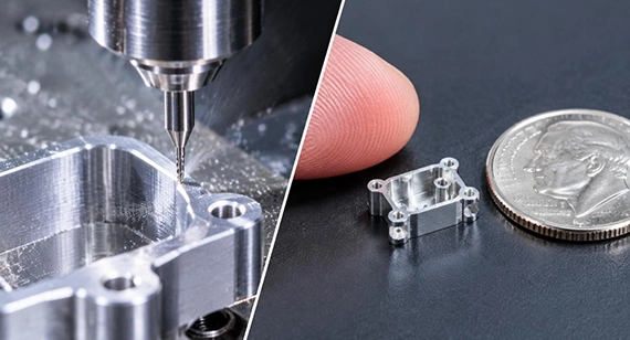
Miniaturization requires cutting tools with diameters ranging from 0.3 mm to 1.5 mm to machine small-radius pockets, miniature splines, and complex cable routing channels. Within this tool diameter range, several machining challenges arise:
2. Tight Tolerances and Joint Alignment
Robotic dexterous fingers rely on cumulative joint assembly accuracy. Even a 0.05° angular deviation at the proximal joint can translate into a significant positional error at the fingertip.
3. Lightweight Structures and Mechanical Rigidity
High dynamic response requirements demand minimal inertia in robotic finger links. This makes hollowed-out and thin-wall structural components necessary, with wall thicknesses typically ranging from 0.5 mm to 0.8 mm.
4. Surface Finish and Friction Control
Surface characteristics directly affect the functional reliability of robotic finger components.
Achieving micron-level tolerances on miniature thin-wall components requires customized machining platforms, cutting parameters, and fixture designs.
1. Comparison of 3-Axis, 4-Axis, and 5-Axis CNC Machining
3-Axis Milling
3-axis milling is primarily suitable for early-stage flat prototypes or planar mounting brackets. Machining multi-face finger links on a 3-axis machine typically requires 4 to 6 independent setups. Datum errors accumulate with each repositioning, causing dimensional deviations to increase significantly (approximately ±0.02 mm per setup).
4-Axis Milling
4-axis milling is suitable for machining cylindrical joint housings through combined turning and milling operations. It allows continuous indexing around a single rotational axis to drill side holes and machine radial pulley grooves.
Simultaneous 5-Axis Machining
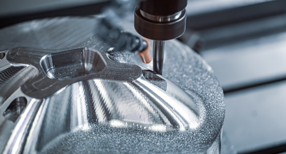
Simultaneous 5-axis machining is the industry benchmark for complex robotic dexterous finger links. Its multi-axis capability allows multi-face undercut pockets, angled cable routing slots, and critical hinge pin bores to be machined within a single continuous setup.
This eliminates datum transfer errors, helps maintain true position and coaxiality within ≤ 0.005 mm, and allows shorter, more rigid cutting tools to be used to minimize chatter.
2. Micro-Machining of Small Holes, Narrow Slots, and Thin Features
Micro-cutting tools with diameters below 1.0 mm require spindle speeds of 24,000 to 60,000 RPM. This helps maintain the optimal cutting speed (Vc) while preventing excessive feed per tooth from breaking brittle carbide cutting edges.
Dynamic radial engagement, typically 5–10% of the tool diameter, combined with a larger axial depth of cut, helps maintain a consistent cutting load and reduce tool deflection when machining thin-wall cavities.
Drilling tendon guide holes as small as Ø0.5 mm through deep cavities requires controlled micro-peck drilling cycles, through-spindle air or mist cooling, and high-precision hydraulic or shrink-fit tool holders to keep total indicated runout (TIR) within 2 μm.
3. Fixture Design and Multi-Operation Accuracy Control
Thin-wall and irregularly shaped finger links cannot withstand the clamping pressure of conventional heavy-duty vises without experiencing permanent elastic deformation.
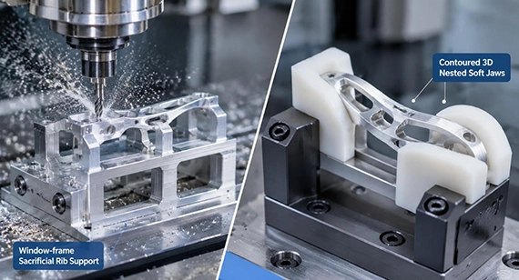
Custom aluminum soft jaws made from 6061 or 7075 are CNC-machined to match the external 3D contour of the workpiece from the first machining operation. This distributes clamping forces across the entire external surface rather than concentrating pressure at isolated points.
Components are machined from solid billet stock while remaining connected to a surrounding support frame through sacrificial ribs. The entire structural link, including internal weight-reduction pockets and hinge bores, is completed before these support ribs are removed during the final light-cutting operation using small-diameter tools.
For ultra-thin structural housings, vacuum fixtures or low-melting-point bismuth alloy backing materials provide solid internal support. This helps eliminate vibration during external profile machining.
4. Deburring and Secondary Operations
Microscopic burrs remaining on tendon entry chamfers, bearing retaining ring grooves, or miniature gear-meshing interfaces can easily lead to mechanical failures.
Low-pressure micro-abrasive wet blasting using 30–50 μm glass beads or ceramic media can remove microscopic tool-edge burrs without rounding critical functional datum edges.
Dedicated edge-breaking toolpaths using Ø0.2 mm ball-end mills ensure that all internal cable cross-holes have smooth, tangent transitions with radii of R0.1–0.2 mm.
All critical intersecting holes must be inspected under 20× to 50× magnification to verify that burrs have been completely removed.
Achieving smooth, zero-backlash joint articulation throughout a dexterous hand containing 15 to 20 joints requires strict geometric dimensioning and tolerancing (GD&T) controls.
1. Dimensional Accuracy and GD&T Control
2. Inspection of Miniature and Complex Features
Verifying sub-millimeter tolerances on non-rigid miniature components requires specialized metrology equipment.
High-Precision Optical Coordinate Measuring Machines (CMM)
Multi-sensor, non-contact optical CMM systems equipped with sub-micron chromatic confocal sensors can measure miniature hole positions, 3D surface profiles, and thin ribs without the probe deflection associated with conventional contact measurement.
Micro-Probe Contact CMM
Ultra-low-force 0.3 mm ruby or diamond stylus probes are used to inspect deep bearing seats and internal retaining ring grooves.
Go/No-Go Gauges and Pneumatic Measurement
Class X and XX plug gauges provide rapid go/no-go verification of hole diameters. Non-destructive pneumatic gauging can also inspect the actual roundness and taper of miniature bores.
3. Surface Roughness and Edge Quality Inspection
White-Light Interferometry and Contact Profilometry
These measurement methods verify surface finish parameters (Ra and Rz) on cable guide surfaces and sliding joints, confirming compliance with specifications as low as Ra ≤ 0.2 μm.
Vision Measuring Machines (VMM)
High-magnification optical projection systems can detect microscopic edge burrs, edge chipping, and incomplete radii along cable contact paths.
4. Assembly Verification and Functional Testing
Pin Insertion Test
Pin components are inserted across multiple assembled links to verify that they can be installed smoothly without external force, helping identify angular misalignment between components.
Rotational Free-Running Torque Test
A miniature torque sensor measures the starting torque of assembled joints. Rotational resistance must remain low and consistent throughout the full range of motion, without any binding points.
The following tips for surface treatments are worth memorizing, because they could change dimensions:
Two identical drawings can differ by a factor of two or three in price, and the difference is almost never the tolerance callouts. It is how much of the geometry fights the tool. These eight choices are the ones that move the quote the most on robotic finger components.
Keep walls at 0.8 mm where you can. 0.5 mm is achievable and sometimes necessary for distal links, but every wall below 0.8 mm adds light-cutting passes, fixture complexity, and scrap risk. Thin only the walls that carry inertia, not every wall on the part.
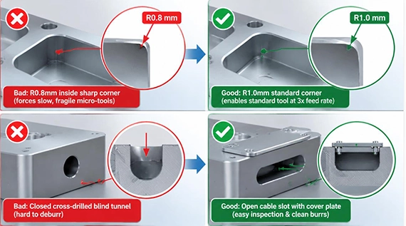
Use standard metric tool radii for internal corners. R0.8 mm forces a small, flexible cutter. R1.0 mm lets the shop run a 2.0 mm endmill at several times the feed rate. Pick radii from the tool catalog, not from the CAD default.
Keep pocket depth under about 3–4× the cutter diameter. Deeper pockets need long-reach tools, which deflect and chatter. If your housing cavity runs deeper than that, consider splitting the housing into two machined halves instead of one deep pocket.
Open the cable channels. A closed cross-drilled tunnel through a link is expensive to drill, hard to deburr, and impossible to inspect. An open slot with a cover plate does the same job, is cheaper, and lets the tendon path be checked visually.
Zone your tolerances. Four to six features define the kinematic chain: pivot bores, pin diameters, bore-to-bore center distance, and the motor pilot. Everything else can live at general tolerance. A drawing with twelve tight features usually gets quoted as a single high-risk part.
Design left and right links as mirror parts on one fixture. Symmetric parts share a soft jaw and a setup, and they halve the number of programs and inspections you have to approve.
Give the deburring tool somewhere to go. Cable entry chamfers, snap-ring grooves and cross-hole intersections need tool access from both sides. If a burr cannot be reached, it will not be removed, and a 30 μm burr in a tendon channel will cut a Dyneema line.
Leave finishing allowance on bores that will be coated. 0.05–0.1 mm on diameter, or an explicit masking note. This is design-side work that saves a rework loop weeks later.
| Component Name | Primary Recommended Material | Alternative Material | Key Engineering Considerations |
| Proximal Finger Link (High Torque) | 7075-T6 Aluminum | Ti-6Al-4V (Grade 5) | Resists bending moments at the base joint and maximizes structural stiffness. |
| Distal Phalanx (Fingertip) | 6061-T6 Aluminum | PEEK / Carbon Fiber | Reduces distal mass and minimizes the angular inertia of finger movement. |
| Motor / Gearbox Housing | 6061-T6 Aluminum | 7075-T6 Aluminum | Balances thin-wall machinability with thermal conductivity. |
| Joint Hinge Pins | 17-4 PH Stainless Steel / 303 Stainless Steel | Ti-6Al-4V Titanium Alloy | Provides wear resistance and helps prevent galling when paired with brass or polymer bushings. |
| Tendon Pulleys and Guide Components | Brass / 303 Stainless Steel | PEEK Engineering Plastic | Offers low friction and strong resistance to cable scoring and wear. |
| Sensor Interface Brackets | 6061-T6 Aluminum | 7075-T6 Aluminum | Facilitates M1.2–M1.6 tapped holes and provides high dimensional stability. |
Explore for More Metal or Plastic Materials for CNC Custom Robotic Dexterous Hand Components
| Audit Category | Technical Audit Requirements |
| Equipment Capability | 5-axis CNC milling centers equipped with high-speed spindles (>24,000 RPM). |
| Micro-Feature Machining | Capability to machine micro-features using tools as small as ≤ Ø0.5 mm and produce precision thin-wall structures. |
| Metrology & Inspection | Equipped with optical 3D CMM systems, micro-bore air gauging equipment, and surface profilometers. |
| Engineering Support | Proactive DFM feedback covering GD&T optimization, machining feasibility, and dimensional compensation for surface finishing. |
| Surface Treatment Control | Strict masking of precision bores and bearing seats, with controlled oversight of anodizing and plating processes. |
| Traceability & Quality Assurance | Complete material certifications, traceable production records, and CMM dimensional First Article Inspection (FAI) reports. |
A leading humanoid robotics R&D team was developing an integrated proximal phalanx and transmission base component for its latest generation of high-dynamic five-finger dexterous hands. Made from 7075-T6 aerospace-grade aluminum alloy, the component integrated a mounting cavity for a miniature frameless torque motor, two sets of miniature bearing hinge bores, and multiple spatially curved tendon routing channels. The overall part measured only 38 mm × 14 mm × 11 mm.
After in-depth discussions with the customer’s engineering team, our engineers identified the main manufacturing challenges.
First, structural rigidity and wall thickness. To reduce the dynamic inertia of finger movement, the local sidewall thickness of the component was reduced to just 0.55 mm.
Second, the Ø3 mm bearing bores in the U-shaped clevises at both ends required coaxiality of ≤ 0.006 mm.
To address these challenges, our engineering team implemented the following solutions:
1. Single-Setup, Continuous 5-Axis Machining Strategy
In a single setup, we coordinated the machining of multi-face weight-reduction cavities, drilling of angled tendon entry holes, and continuous precision boring of the hinge bearing bores at both ends. This unified-datum process avoided cumulative datum errors caused by repeated setups, ensuring that the spatial geometric relationships remained consistent with the CAD model.
2. Contoured Nested Soft Jaws Combined with Window-Frame Residual Material Support
To prevent deformation of the thin walls under machining forces, we kept the part connected to the surrounding stock frame during the initial machining stages. This window-frame support method allowed us to finish the internal weight-reduction cavities and precision bores while the component retained the rigidity of the surrounding frame.
During final contour machining and part separation, we used custom 7075 aluminum contoured nested soft jaws, designed to match the workpiece's 3D surfaces. These jaws provided full-area, evenly distributed clamping force across the curved surfaces, helping prevent excessive elastic bending and springback.
3. High-Speed Dynamic Trochoidal Milling and Micro-Peck Drilling
For the 0.55 mm ultra-thin-wall areas, we used high spindle speeds combined with small radial stepovers in a dynamic trochoidal milling strategy, keeping the radial width of cut (ae) below 6% of the tool diameter. The resulting low instantaneous cutting forces effectively suppressed machining chatter and improved the surface finish to Ra 0.4 μm.
For the slender Ø0.6 mm tendon holes with a depth of 12 mm, we switched to ultra-hard micro-grain carbide micro-drills and a high-pressure through-spindle coolant and oil-mist system.
Combined with an optimized micro-peck drilling cycle, this ensured smooth chip evacuation and prevented micro-drill breakage and bore-wall scratching caused by chip blockage.
Results
Following iterative process optimization, the batch of 300 proximal phalanx components for robotic dexterous hands was successfully delivered for mass production and passed full-assembly testing.
The coaxiality of the bearing bores in the clevises at both ends was consistently maintained within the design requirement of ≤ 0.006 mm.
Full-dimensional inspection of the 0.55 mm thin-wall areas using a confocal optical 3D scanner verified that the profile deviation remained within ±0.012 mm, with no chatter marks or warping.
As robotics moves toward industrialization and large-scale deployment, dexterous hands are not only responsible for performing complex manipulations but also represent the capabilities of micromechanics and precision manufacturing. From thin-wall deformation control in finger links and precision machining of actuator joint cavities to micron-level machining of fine tendon channels, these manufacturing requirements cannot be met by advanced CNC machine tools alone. They also require manufacturers to understand robotic finger kinematics, material mechanics, cutting stress evolution, and the dimensional effects of surface treatments, supported by extensive machining experience.
Does your team face manufacturing challenges when prototyping or mass-producing robotic dexterous hands, highly integrated miniature mechanical joints, or precision microstructures? These may include thin-wall distortion, wall thickness deviations, joint binding caused by excessive coaxiality errors, or hidden burrs inside fine tendon routing holes that cause cable wear and breakage. Contact our precision manufacturing engineering team for a comprehensive Design for Manufacturability (DFM) review and end-to-end precision CNC machining solutions. [We support 2D Drawings (PDF files), 3D Drawings (IGS/STP/STEP files)].
Send your 2D drawings, 3D CAD models, material, hinge and bearing fit requirements, coaxiality targets, wall thicknesses, tendon-routing features, surface finish, coating requirements, prototype quantity and production quantity. VMT will review DFM, micro-machining feasibility, datum strategy, thin-wall stability, burr-control risks, coating allowances, inspection and quotation requirements.
All information and uploaded files are secure and confidential.
1 Tell us what you need
2 Get solution & quote
3 Approve production
Email: inquiry@vimetal.com.cn
1. Is CNC Machining Better Than 3D Printing for Custom Robotic Dexterous Hand Manufacturing?
In most cases, yes. CNC machining offers clear advantages for load-bearing and rotating joint components. Joint hinge pins and bearing seats in dexterous hands require extremely high fit accuracy (such as H6/H7 tolerances) and coaxiality, which CNC machining can consistently control at the micron level. Meanwhile, CNC-machined parts made from isotropic metal bar stock or forgings offer far greater fatigue strength and rigidity than 3D-printed parts with potential interlayer defects. However, for complex topology-optimized structures where high rigidity is not required, 3D printing followed by secondary CNC machining can be considered.
2. Why Is Aluminum Alloy Widely Used in Robotic Dexterous Hand Manufacturing?
Aluminum alloys offer an excellent strength-to-weight ratio. Grades such as 7075-T6 and 6061-T6 are particularly suitable for these applications and are also well suited to CNC machining, making it possible to achieve high dimensional stability and surface quality. In addition, aluminum has excellent thermal conductivity and can serve as a heat-dissipating housing for miniature motors inside enclosed joints. Combined with anodizing, its corrosion and wear resistance can also be improved, while various color options can be achieved.
3. How Can Robotic Finger Components Be Made Lighter Without Sacrificing Strength?
First, use Finite Element Analysis (FEA) for topology optimization to remove material from low-stress areas and create thin-wall structures with localized reinforcing ribs or I-beam cross-sections. Second, select materials according to load distribution: use high-strength 7075 aluminum or titanium alloys for proximal phalanges that experience higher loads, and 6061 aluminum or even engineering plastics for distal fingertips. Third, use simultaneous 5-axis machining to achieve part integration by combining separately manufactured bearing seats, brackets, and guide channels into a single component, eliminating unnecessary screw connections and flanges.
4. What Is the Difference Between a Robotic Dexterous Hand and a Robotic Gripper?
Industrial grippers typically have only 1 to 2 degrees of freedom (DoF) and grip objects of fixed dimensions through rigid linear movement or a simple opening-and-closing motion. Their structures are robust but lack flexibility. Robotic dexterous hands, in contrast, are highly anthropomorphic mechanical systems, typically featuring more than a dozen or even over twenty degrees of freedom. Each finger contains multiple active or passive joints and integrates miniature motors, tendon-driven transmission mechanisms, and tactile sensors, enabling pinching, adaptive enveloping grasps, and complex fine manipulation.
5. What Factors Determine the Manufacturing Cost of Custom Robotic Finger Components?
The manufacturing cost of dexterous hand components mainly depends on several factors: part geometry and the number of machining axes (such as the machining time and hourly rates for 5-axis machining and micro-milling), tolerance requirements (tighter GD&T tolerances and more miniature deep holes increase scrap rates and inspection costs), material type (titanium alloys are significantly more expensive to machine than aluminum alloys), surface treatment and precision masking operations, and, most importantly, order quantity. Generally, single-piece prototypes must absorb the high initial programming and fixture costs, while the unit cost decreases significantly once production moves to larger batches.
6. Can CNC Machining Support Both Robotic Finger Prototyping and Mass Production?
Absolutely. During the prototyping stage, CNC machining requires no expensive molds and can deliver high-precision metal parts within a few days based on 3D drawings, once the drawings and toolpaths are finalized. During mass production, the process can transition seamlessly to multi-station automated fixtures, horizontal machining centers, or Swiss-type lathes. Combined with standardized toolpaths and batch CMM inspection procedures, this significantly reduces individual machining cycle times while ensuring dimensional consistency across large production volumes.
The technical information and manufacturing advice shared on the machining-custom.com website are for general guidance only. While we strive for accuracy, machining-custom.com does not guarantee that the processes, tolerances, or material properties mentioned are applicable to every specific project. Any reliance you place on such information is strictly at your own risk. It is the buyer's responsibility to provide definitive engineering specifications for any production orders. Final specifications and service terms shall be subject to the formal contract or quotation confirmed by both parties.


 +86 15099911516




 Read more