16 years one-stop China custom CNC machining parts factory

Hey there I’m VMT Sam!
With 25 years of CNC machining experience we are committed to helping clients overcome 10000 complex part-processing challenges all to contribute to a better life through intelligent manufacturing. Contact us now
 68 |
Published by VMT at Nov 11 2026 | Reading Time:About 6 minutes


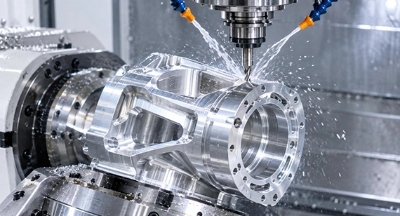
Takeaways: Why CNC Machining Dominates Robot Joint Housings
For custom robotic joint housings ( or enclosures, casings) subjected to high-torque dynamics and continuous transmission loads from harmonic drives or RV reducers, CNC machining remains the undisputed manufacturing standard. It delivers superior isotropic rigidity, extreme coaxiality tolerances (±0.005 mm to ±0.01 mm), and exceptional heat dissipation that additive methods cannot match. Beyond structural containment, a precision-machined joint casing serves four critical functional roles: maintaining IP65/IP67 hermetic sealing, aligning dual bearing journals, dissipating thermal build-up from frameless torque motors, and providing essential electromagnetic interference (EMI) shielding for sensitive encoders. For high-precision robotic joints, these functions must be considered together with datum strategy, wall thickness, material selection, surface finishing, and assembly tolerances from the DFM stage.
Case Study Overview
The end section shows a case study of how 5-axis single-setup machining with contoured soft jaws took a client's cobot wrist casing from 0.024 mm coaxiality to 0.006 mm, removing vibration and cutting motor temperature 11°C.
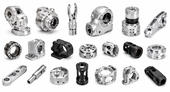
In modern articulated robotics, cobots, and surgical arms, a custom joint casing serves as the load-bearing structural component of the drive unit. Inside each housing sit precision components including the reducer, frameless motor, encoders, and cross-roller bearings.
During regular operation, such as rapid acceleration, braking, and direction changes, the casing handles three main stresses:
CNC machining is well-suited for these demands. As a subtractive process, it cuts the casing directly from a solid block of forged or wrought metal, such as 6061-T6/7075-T6 aluminum or 304/316stainless steel or C3600 brass . Cutting from solid stock avoids the internal air pockets (porosity) common in casting and the weak layer bonding seen in 3D printing, giving the part reliable strength under repeated loads.
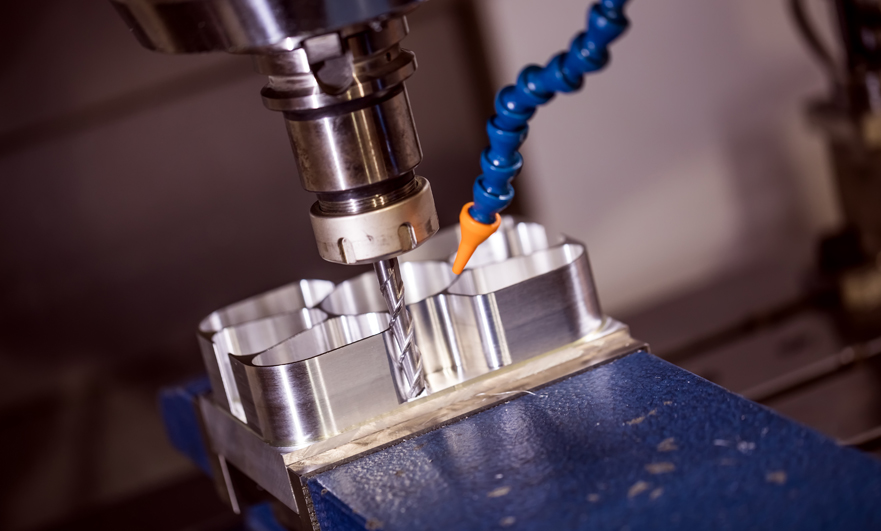
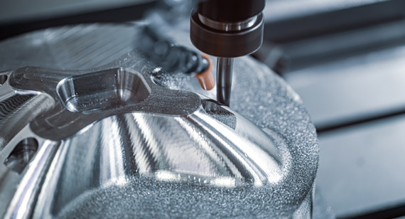
In addition, 5-axis CNC machining allows complex outer shapes, deep bearing bores, and mounting holes on different faces to be machined in a single setup. Machining both sides without un-clamping the part reduces alignment errors and keeps the bearing bores coaxial, which helps prevent uneven gear wear and joint noise.
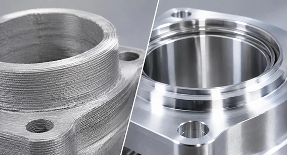
Industrial 3D printing (such as SLM for metal and SLS for nylon) is useful for quick concept models and complex internal shapes. However, when moving to functional, load-bearing robot joint enclosures, CNC machining offers clear practical advantages in four key areas:
1. Uniform Strength vs. Layer Weakness
2. Tight Tolerances & Bearing Fits (GD&T)
3. Sealing Performance (IP65 / IP67)
4. Surface Finishing & Anodizing Consistency
What kind of quality you can expect from CNC machining? Here is a quick reference table.
These values represent the difference between "standard" machining and the high-precision requirements typical for robotics.
| Metric | Standard CNC | High-Precision Standard | Inspection Tools |
| Linear Tolerance | ±0.05 mm | ±0.005 mm ~ ±0.01 mm | CMM |
| Coaxiality | 0.02 mm | ≤ 0.008 mm | CMM / Air Gauge |
| Flatness | 0.05 mm | ≤ 0.01 mm | Interferometer |
| Roughness (Ra) | Ra 1.6 μm | Ra 0.4 μm ~ Ra 0.8 μm | Profilometer |
| Thread Fit | 6H / 2B | 6H / 4H | Go/No-go Gauges |
1.Thin-Wall Machining: Avoiding Distortion
It is common to see thin walls (1.0mm–1.5mm) in robot casings to save weight. However, these thin areas tend to "chatter" or warp because the material has less structural support while being cut.
2.Material Selection: Balancing Precision and Cost
When choosing a material, think about your project stage. For prototypes, 6061-T6 aluminum is honestly one of the best choices. It’s affordable, easy to machine, and gives a great surface finish (e.g. Ra 0.8μm) easily, which is perfect for early testing.
When the housing design needs more strength later, you can step up to 7075-T6 aluminun. It’s tougher and more stable for high-precision bearing fits, though it costs about 30–50% more.
The titanium alloys are also acceptable, just keep in mind these are usually much harder to cut, expect to pay 3–5 times more than you would for aluminum.
3.Datum Alignment: Why "Reference Points" Matter
Think of the casing as a sandwich, the motor mounts on one side, the gearbox on the other, and the bearings sit in the middle. The "datum" is basically the master reference point for all measurements.
When the input and output axes are off by even 0.02mm, the gearbox will bind, heat up, and eventually wear out. Thus, it is recommended to define your motor and gearbox mounting holes from the same primary datum on your prints.
This is also why the machining shop prefer to machine both sides in a single 5-axis setup to ensure everything is perfectly aligned from the start.
4.Surface Finishing, Masking, and Thread Accuracy
Most robot housings go through bead blasting and anodizing to resist scratches. But here’s the catch: anodizing adds a thin layer (10–25μm) to the surface. When this is not accounted, the bearings won’t fit, and the threads will be too tight.
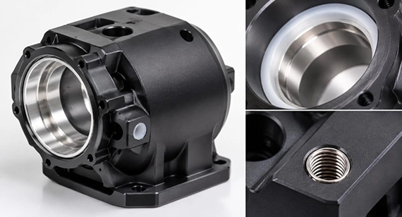
To be blunt, yes—prototyping robot joint housings isn't cheap. The biggest cost isn't just the material; it’s the engineering setup. When you send a file for a prototype, the CNC machining factory have to write the program, set up the machine, and often make custom fixtures just for your design. When you change the design, the shops also have to start that process over.
That’s why starting with 6061 aluminum for your first few test rounds is recommended. It’s the most economical way to prove your design works. Once you’re satisfied with the design and ready to move to a batch of, for like, over 500, those high "setup costs" can be saved because the same program and fixtures can be reused. That’s when the price per part really drops, making the whole process much more cost-effective.
Practical robot joint manufacturing is often about finding the right sequence of operations. Here is how a practical change in the machining setup solved an assembly issue for a collaborative robot (cobot) wrist joint casing.
The Challenge
A robotics startup was testing their 6-axis cobot prototype. During continuous cycling tests, the wrist joint experienced abnormal motor heat, minor vibration, and a slight high-frequency whine. After inspecting the harmonic reducer, the engineering team noticed premature wear on the input shaft bearings, pointing to a misalignment somewhere in the housing.
Root-Cause Analysis
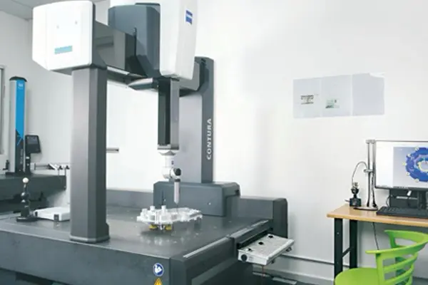
When the team brought the casing to our shop for a coordinate measuring machine (CMM) inspection, the data showed:
The issue was not poor machining skill; it was the clamping method. The previous shop had machined side A on a 3-axis CNC, flipped the part over in a standard vise, and cut side B. Clamping down on a 1.3 mm aluminum wall caused subtle elastic deflection. Once unclamped, the metal bounced back, throwing the two bores slightly out of alignment.
The Machining Solution
To keep the two opposing interfaces aligned, we adjusted the manufacturing approach:
The Result
The robotics industry is moving fast. With the rise of humanoid robots, quadruped platforms, and compact cobots, joint casings are being pushed toward thinner walls, integrated cooling channels, and lighter materials. Meeting these tight mechanical requirements comes down to sensible Design for Manufacturability (DFM), selecting the right alloy, budgeting for surface treatments, and matching tolerance expectations with the right machine setup. Whether you are facing a feasibility analysis for datums or wall thicknesses, looking for custom solutions to lower robot prototyping costs, or unsure about which material your project requires, feel free to send your requirements to our engineering team. We are happy to review your wall thicknesses, recommend proper datums, and provide a clear, itemized quote for your prototype run. [We support 2D Drawings (PDF files), 3D Drawings (IGS/STP/STEP files)].
Send your 2D drawings, 3D CAD models, material, bearing and gearbox interface requirements, datum scheme, critical tolerances, wall thickness, surface finish, prototype quantity and production quantity. VMT will review DFM, 5-axis machining strategy, thin-wall deformation control, fixturing, coating allowances, inspection and quotation requirements.
All information and uploaded files are secure and confidential.
1 Tell us what you need
2 Get solution & quote
3 Approve production
Email: inquiry@vimetal.com.cn
Q1: 6061 vs. 7075 Aluminum: Which alloy is best for custom robot joint housings?
6061 vs. 7075 Aluminum: 6061 is the most cost-effective choice for early functional prototypes and general robot arms. It offers excellent machinability and consistent anodizing. Use 7075 for high-torque pivots (shoulders/waists) requiring greater yield strength and thread pull-out resistance.
Q2: What is the minimum wall thickness for CNC machined robot enclosures?
While 0.8 mm is technically possible, 1.2 mm to 1.5 mm is the practical engineering standard. Walls thinner than 1.2 mm increase the risk of chatter marks during cutting and structural warping upon release from the machine fixture.
Q3: Can PEEK or POM plastics replace aluminum for robot joint casings?
Not the best choices. These plastics suit lightweight inspection robots or cleanroom arms requiring electrical insulation. However, they lack the mechanical rigidity to resist torsional twisting in high-reduction gearboxes and fail to dissipate heat as effectively as aluminum.
Q4: How do I prevent thread stripping in aluminum joint casings?
Aluminum threads often wear during repeated testing. Specify stainless steel Helicoils or threaded inserts (e.g., Keenserts) on your technical drawings for the critical mounting points.
Q5: How should I specify hole tolerances for parts undergoing hard anodizing?
Hard anodizing (Type III) adds 25–50 µm to the surface. You should label the drawing dimensions as "Pre-Plate" or "Post-Plate." For tight bearing bores (e.g., H7), our manufacturing factory support process involves applying silicone masking plugs to preserve the original machined bore diameter.
Q6: What is the typical lead time for prototype joint casings?
Standard and simple prototype casings require 5 to 8 business days for engineering review, CAM programming, and final anodizing. For designs involving complex gear interfaces, our guide on CNC Machined Robot Joint Housings and Critical Components covers advanced procedures for concentricity and gear assembly.
The technical information and manufacturing advice shared on the VMT website are for general guidance only. While we strive for accuracy, VMT does not guarantee that the processes, tolerances, or material properties mentioned are applicable to every specific project. Any reliance you place on such information is strictly at your own risk. It is the buyer's responsibility to provide definitive engineering specifications for any production orders. Final specifications and service terms shall be subject to the formal contract or quotation confirmed by both parties.


 +86 15099911516



 Read more