16 years one-stop China custom CNC machining parts factory

Hey there I’m VMT Sam!
With 25 years of CNC machining experience we are committed to helping clients overcome 10000 complex part-processing challenges all to contribute to a better life through intelligent manufacturing. Contact us now
 73 |
Published by VMT at Nov 09 2026 | Reading Time:About 6 minutes


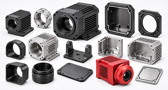
For smart thermal imaging systems, a CNC-machined camera housing is not merely a protective enclosure; it is part of the optomechanical, thermal, sealing, and EMI performance chain. Reliable housing design requires the optical datum, thin-wall stability, thermal-contact surfaces, O-ring sealing geometry, internal component interfaces, and surface-treatment allowances to be planned together during the DFM stage. When these relationships are controlled as one integrated system, manufacturers can reduce optical misalignment, thermal drift, assembly interference, sealing failures, and costly rework before volume production.
Article Roadmap
To help engineering teams bridge the gap between 3D CAD models and stable, repeatable field performance, this guide breaks down the core manufacturing principles behind high-reliability thermal camera enclosures:
In smart infrared vision systems, custom CNC machined enclosures are not just protective covers. They function as a critical optomechanical and thermal structural assembly. Common situations are like such: The dimensional accuracy of a custom CNC machined housing dictates the optical alignment between the infrared core, the focal plane array (FPA), and the germanium (Ge) window. Internally, machined thermal-contact interfaces and heat-dissipating geometries govern sensor stability, which impacts Noise Equivalent Temperature Difference (NETD) and radiometric measurement accuracy. Externally, precision-machined gland interfaces and conductive mating surfaces provide the baseline sealing and electromagnetic shielding (EMI) required to survive demanding industrial and defense field environments. And so on, and the list could go on. Below, let us examine these specific application scenarios, the existing issues, their solutions, and design recommendations.
Many thermal imaging cameras operate in environments far more punishing than common optical systems. The housings need to maintain optical alignment, seal against corrosive ingress, and stabilize detector core temperatures. Designing these CNC machined casings requires tailoring the alloy, wall thickness, and internal features to the target operating conditions.
Below, Check The Image:
Nine Target Scenarios:
Operating Conditions vs. CNC Enclosure Technical Specifications
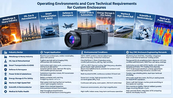
Heavy Industry, Metallurgy & Petrochemical (High Heat, Corrosive & Explosive Zones)
Thermal monitoring in pyrometallurgical processing and petrochemical refining represents the extreme end of enclosure survivability:
Internal Fluidic Channels in Refractory Alloys: In blast furnace and ladle inspection applications, ambient radiant temperatures range from 200°C to 400°C. Standard aluminum alloys lose structural temper and conduct excessive heat to the sensor. Enclosures in this category must be CNC machined from corrosion- and heat-resistant alloys such as AISI 316L stainless steel or Hastelloy C-22/C-276. The internal housing geometry frequently requires integrated dual-circuit fluid channels (water or purge air cooling). These deep, convoluted flow passages demand multi-axis drilling or split-chamber CNC milling followed by precision vacuum brazing to maintain pressure integrity up to 1.5 MPa without internal leakage.
Flameproof (Ex d) Mechanical Tolerances (ATEX / IECEx Zone 1 & 2): In hydrocarbon processing facilities, the enclosure must prevent an internal electrical spark or explosion from igniting the surrounding volatile atmosphere. This places extreme demands on the CNC machined joints. Flanged, cylindrical, and threaded flamepath joints must comply with rigid dimensional standards:
Defense, Aerospace & ADAS Mobility (Dynamic Vibration, High G-Loads & Thermal Shocks)
In vehicle-mounted mobility and defense optronics, the mechanical housing must maintain optical convergence despite continuous dynamic vibration, thermal cycling, and ballistic shock:
Energy Storage, Power Grids & Marine Infrastructure (High EMF, Sealing & Marine Corrosion)
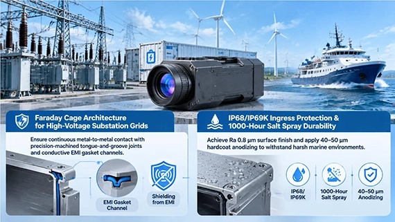
Outdoor installations expose thermal cameras to severe atmospheric corrosion, high voltage fields, and torrential washdowns:
Engineering teams frequently encounter an expensive paradox during prototype integration: every individual dimension on the inspection sheet falls within drawing tolerances, yet the assembled camera fails during testing. Typical failure modes include:
The root cause of these integration failures is rarely machine capability alone. Instead, it stems from treating the enclosure as isolated features rather than designing and machining it around a Unified Datum System, coupled with inadequate control over material stress release during deep-cavity CNC milling.
For smart thermal cameras, mechanical tolerances affect optomechanical alignment. Minor dimensional or geometric errors in the enclosure can cause optical tilt, sensor defocus, and connector binding. In design and DFM reviews, three structural areas require careful tolerance control: thin-wall stability, datum continuity, and internal component interfaces.
Deep-cavity housings typically require removing more than 75% of raw material from the billet, which releases residual stresses and can cause thin walls (1.5 to 2.5 mm) to bow or twist. To maintain wall parallelism within 0.02 mm, the process should separate heavy roughing from final finishing with an intermediate stress-relief step. Additionally, designing gradual wall transitions with corner radii of R 1.5 mm or greater helps reduce localized stress concentration.
Optical performance depends on precise coaxial alignment across the front germanium (Ge) window seat, the lens mounting thread, and the internal thermal core pocket. When these features are machined in separate setups, chucking and repositioning errors stack up. By defining the primary optical axis as the primary datum (Datum A) and machining the lens interface and core mount in a single 5-axis setup, concentricity and perpendicularity can be maintained within 0.01 mm or less, preventing bore-sight shift.
Internally, enclosures need accommodate sensor boards, processing modules, and I/O connectors in a confined layout. To prevent mechanical strain on circuit boards during assembly, all PCB mounting bosses must maintain a coplanarity of less than 0.02 mm; uneven bosses can flex the PCB and damage solder joints. Furthermore, cutouts for sealed circular connectors and USB interfaces should be dimensioned directly from PCB locating pins rather than exterior enclosure edges, holding true position within +/-0.03 mm to prevent cable interference and assembly binding.
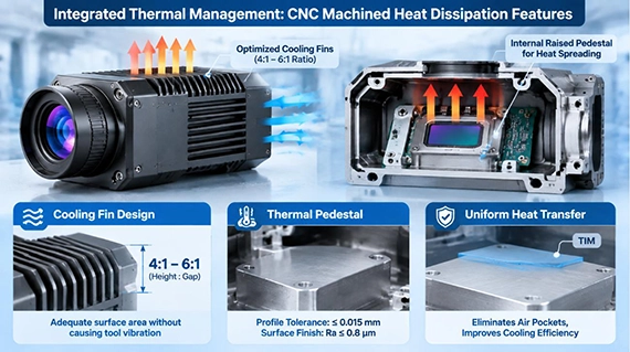
Uncooled thermal detector cores are sensitive to ambient temperature drift; localized heat buildup degrades measurement accuracy and causes image noise. Integrating heat management features directly into the CNC enclosure eliminates the contact thermal resistance of secondary bolt-on heat sinks.
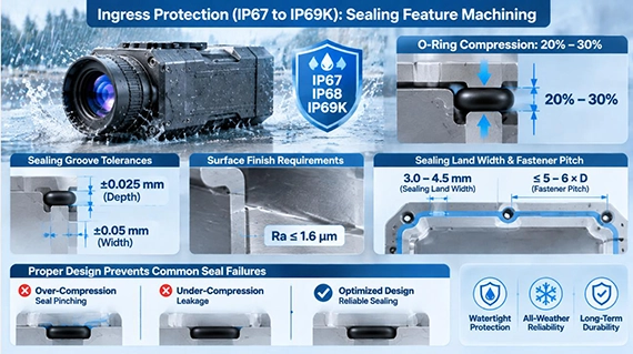
Field failures in outdoor thermal cameras are frequently caused by moisture ingress along enclosure mating splits. Achieving reliable IP67, IP68, or IP69K sealing requires precise control over gland geometry, surface texture, and flange stiffness.
O-ring performance depends on consistent elastomeric compression between 20% and 30%. In rectangular and dovetail sealing grooves, depth tolerances must be held within +/-0.025 mm and width tolerances within +/-0.05 mm.
Variations beyond these limits lead to either over-compression and seal pinching or under-compression and leakage. Furthermore, cutting tool feed marks along the groove floor and side walls must not exceed Ra 1.6 um; spiral cutter marks across sealing lands act as microscopic capillary leak paths under external water pressure.
Equally critical is the mechanical rigidity of the sealing flange. When fastener spacing is too wide or cover lands are too thin, bolt torque causes the cover plate to bow between fasteners.
Maintaining a minimum sealing land width of 3.0 to 4.5 mm, paired with a maximum fastener pitch of 5 to 6 times bolt diameter, ensures uniform clamping pressure across the gasket perimeter and prevents localized gaps.
Surface treatments protect housings from corrosion and stray optical reflections, but they introduce physical film thickness that alters finished dimensions.
Type III hardcoat anodizing deposits a layer typically 25 to 50 um thick. Because hardcoat penetrates the base metal by roughly 50% and builds outward by 50%, an applied 30 um coating increases external diametrical dimensions by approximately 30 um and reduces internal bore diameters by the same amount. For precision features such as lens threads (e.g., M34 x 0.5) and bearing bores, pre-plating machining dimensions must incorporate a dimensional offset; failure to calculate this growth results in thread binding and press-fit interference.
Where dimensional growth cannot be tolerated, dedicated masking is necessary. Custom silicone plugs or precision fixtures must shield optical seating shoulders, O-ring sealing faces, and internal Faraday grounding points during the anodizing bath. Masking internal electrical grounding pads preserves metal-to-metal contact for low-impedance EMI shielding.
Finally, specifying a matte black anodized finish on interior optical cavities minimizes internal infrared light reflections, while racking contact marks must be constrained to designated, non-critical external surfaces.
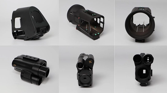
An industrial equipment manufacturer faced reliability failures during pilot testing of a high-temperature monitoring thermal camera. Prototypes sourced from a general machine shop showed three major defects:
Failure analysis revealed that the issues stemmed from cumulative datum errors, uneven bolt clamping, and high interface thermal resistance.
To resolve the thermal bottleneck, the bolt-on copper heatsink was replaced with a monolithic 6061-T6 aluminum CNC housing featuring integrated external cooling fins (5:1 aspect ratio). The internal contact pedestal was finished to a profile tolerance of 0.012 mm and Ra 0.6 um, eliminating micro-gaps under the thermal pad.
Optical alignment was stabilized by migrating to a single-setup 5-axis process. The front lens thread, optical window seat, and internal sensor bosses were cut from a common reference axis (Datum A), locking coaxiality within 0.006 mm.
Sealing and fit issues were resolved through specific mechanical updates:
In a 200-piece pilot run, operating temperature dropped from 76°C to 49°C, optical concentricity held within 0.005 mm, IP67 leak tests achieved 99.8% pass rates, and first-pass assembly yield reached 99.1%.
The manufacturing of smart thermal imaging enclosures is a complex optomechanical task that extends beyond standard CNC machining. Success relies on balancing rigorous thermal management, unified datum-based geometric control, and precise sealing engineering. By integrating these DFM principles early in the development cycle, your design teams can resolve thermal throttling, optical misalignment, and ingress failures before committing to costly production runs. For high-performance vision system developing, ensuring that your enclosure design accounts for these manufacturing realities will significantly improve your product's field reliability.
Have an upcoming thermal vision project or experiencing assembly/thermal failures on current enclosures?
Review our full manufacturing capabilities in custom aluminum smart thermal camera housing and enclosure machining, or send your 3D CAD models and 2D engineering drawings to our DFM engineering team for a free tolerance and thermal manufacturability review within 24 hours. [ We support 2D Drawings (PDF files), 3D Drawings (IGS/STP/STEP files)].
Send your 2D drawings, 3D CAD models, material, optical datum requirements, thermal-management requirements, sealing targets, critical tolerances, surface finish, prototype quantity and production quantity. VMT will review DFM, datum planning, thin-wall machining, heat-dissipation features, sealing interfaces, coating allowances, inspection and quotation requirements.
All information and uploaded files are secure and confidential.
1 Tell us what you need
2 Get solution & quote
3 Approve production
Email: inquiry@vimetal.com.cn
How is optical alignment ensured in enclosures with multi-component designs?
By utilizing a single-setup 5-axis machining process. Referencing the primary optical axis as the master datum (Datum A) allows the lens seat, threads, and internal sensor mounting bosses to be finished in one operation, which minimizes tolerance stacking.
What determines the lead time for custom smart thermal camera casing prototypes?
Lead times typically range from 5 to 10 working days, primarily driven by geometric complexity, the number of machine setups required, and the specific surface finishing processes (such as hardcoat anodizing or powder coating) specified in the design.
Why does integrated thermal design prevent thermal throttling?
Traditional bolt-on heat sinks often suffer from high contact resistance due to interface gaps. Integrating cooling fins and internal contact pedestals directly into the CNC housing provides a continuous, high-conductivity path, facilitating more efficient heat transfer from the sensor board to the environment.
Can you machine thermal enclosures from materials other than aluminum?
Yes. For extreme industrial environments, we machine enclosures from 316L stainless steel, Hastelloy, and other corrosion-resistant alloys, specifically tailoring the CNC milling paths to the physical properties of each material.
How do you manage the dimensional growth of Type III Hardcoat anodizing?
We calculate the coating growth in the pre-machining phase. For a standard 30-50 um hardcoat, we offset the raw machining dimensions so that the finished part meets drawing tolerances after the plating process.
Beside thermal imaging housings, can you manufacture custom night vision housings to a tight tolerance?
Yes, for critical optical and sensor mounting interfaces, high-precision CNC machining can maintain geometric tolerances within +/-0.005 mm to +/-0.01 mm, which is essential for ensuring that Custom CNC Night Vision & Thermal Imaging Housings meet the rigorous alignment standards of modern high-resolution vision systems.
The technical information and manufacturing advice shared on the VMT website are for general guidance only. While we strive for accuracy, VMT does not guarantee that the processes, tolerances, or material properties mentioned are applicable to every specific project. Any reliance you place on such information is strictly at your own risk. It is the buyer's responsibility to provide definitive engineering specifications for any production orders. Final specifications and service terms shall be subject to the formal contract or quotation confirmed by both parties.


 +86 15099911516




 Read more