16 years one-stop China custom CNC machining parts factory

Hey there I’m VMT Sam!
With 25 years of CNC machining experience we are committed to helping clients overcome 10000 complex part-processing challenges all to contribute to a better life through intelligent manufacturing. Contact us now
 97 |
Published by VMT at Nov 04 2026 | Reading Time:About 8 minutes


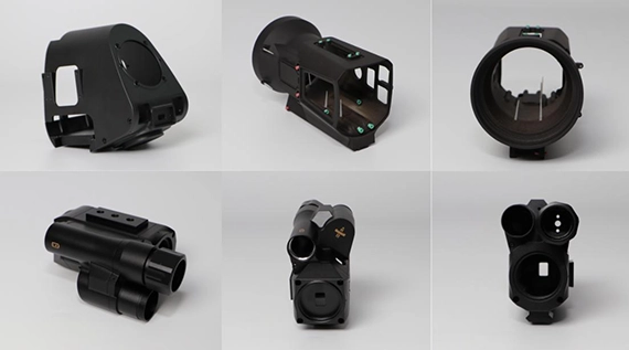
For custom CNC machining projects involving night vision and thermal imaging equipment housings, tolerance design, sealing design, and cost optimization require careful consideration during the design stage. This includes defining the primary optical datum, optimizing internal corner radii, allowing 0.02–0.05 mm for coating thickness compensation, and selecting suitable materials based on the actual operating environment. For example, 7075-T6 aluminum is suitable for high-strength, lightweight UAV imaging housings, while corrosion-resistant 316L stainless steel is a suitable choice for marine monitoring imaging housings. These considerations help reduce CNC machining costs and scrap and rework costs while meeting requirements for boresight shift below 0.5 MOA and IP67/IP68 protection.
In addition, the capabilities of the CNC machining supplier also play an important role. These include establishing a well-planned optomechanical datum system, accounting for machining stress relief in advance, and controlling coating-related dimensional changes and vibration during thin-wall machining.
Overview
This article covers practical DFM guidelines, from material selection and sealing groove design to preventing thin-wall deformation and tolerance stack-up, as well as optimizing manufacturing costs. At the end, we share a case study in which our factory machined and produced high-concentricity AL6063-T6 camera lens housings for a well-known camera brand. The project addressed the previous supplier's challenges, including thin-wall machining chatter, thread seizure after anodizing, and excessive concentricity deviations, which had resulted in a prototype first-pass yield of less than 70%. Through our manufacturing and process improvements, we achieved a mass-production assembly yield consistently above 99.5%.
The environmental loads and performance requirements for night vision and thermal imaging equipment housings vary across different applications. When selecting materials for a new product housing, it is recommended to consider the actual operating environment and evaluate material stiffness, corrosion resistance, coefficient of thermal expansion (CTE), vibration resistance, and other relevant properties.
The following material selection matrix summarizes commonly used engineering materials and key considerations for typical applications. It can serve as a reference for preliminary material selection during the early stages of a project.
| Application | Key Challenges | Recommended Material | Engineering Rationale |
| UAV & Airborne Imaging | Lightweight requirements, high-frequency vibration, airflow impact | AL7075-T651 / Magnesium Alloy AZ31B | AL7075 is preferred for its high strength-to-weight ratio. Use pocketing to reduce weight while maintaining stiffness in thin-wall areas and minimizing the risk of boresight shift. |
| Automotive & Mobility | Severe impact, thermal expansion across a wide temperature range, stone impact | AL6061-T6 / AL6082-T6 | These materials offer good toughness and fatigue resistance. Consider the CTE differences between the metal housing and infrared germanium or chalcogenide glass windows, and allow appropriate elastic clearance. |
| Marine & Offshore Observation | High salt spray corrosion, prolonged humidity, underwater immersion | 316L Stainless Steel / AL5083 / Hard-Anodized 6061 | Select corrosion-resistant materials and protective treatments based on actual environmental conditions. Aluminum parts may use Type III hard anodizing, while exposed fasteners are recommended to use passivated 316L stainless steel. |
| Public Safety & Emergency Response | Accidental drops, handheld portability, rapid temperature changes | AL6061-T6 / Localized Overmolding | Apply protective chamfering (Chamfering ≥1.0mm) to housing edges, with particular attention to impact-prone areas such as eyepiece threaded interfaces and battery compartments. |
| Industrial Inspection & Predictive Maintenance | Chemical corrosion, alignment stability under frequent use | AL6061-T6 / Electroless Nickel Plating | For environments involving prolonged exposure to industrial oils and acidic or alkaline media, electroless nickel plating can be considered. It offers good corrosion resistance and relatively uniform coating thickness distribution. |
| Security & Remote Surveillance | Long-term exposure to sunlight and rain, continuous operation, mechanical stability | Die-Cast A380 (Mass Production) or Extruded 6063 | Focus on long-term structural stability. The gimbal mounting surface should provide sufficient contact area to improve mounting stability and optical calibration repeatability. |
| Outdoor Observation & Wildlife Monitoring | Variable humidity, sweat corrosion, lightweight requirements | AL6063-T6 / PEEK (Specialty Components) | AL6063 offers good extrusion properties and anodizing appearance, making it suitable for products balancing cost and appearance. Matte black or camouflage finishes can help reduce reflections in outdoor environments. |
| Scientific & Environmental Monitoring | Ultra-low or high-temperature measurement, high optical stability requirements | Invar / Titanium Alloy (TC4 / Grade 5) | For systems sensitive to dimensional changes caused by temperature variations, low-CTE materials can be selected based on the operating temperature range and structural requirements to control optical path difference (OPD) changes across the full temperature range. |
Overall, material selection for custom precision night vision and thermal imaging equipment casings requires a balance between structural strength, environmental adaptability, optical stability, and manufacturing cost. After selecting the material, its CNC machinability, compatibility with surface treatments, and subsequent assembly requirements should also be evaluated to avoid additional costs during machining or assembly, even when the material itself meets the required performance specifications. In other words, the recommended materials above should not be applied universally to all similar products. Actual material selection still needs to be evaluated based on the housing structure and specific operating conditions.
The following focuses on key considerations during drawing preparation, tolerance specification, and structural design, helping you identify potential manufacturing risks in advance and reduce rework and scrap during subsequent CNC machining, surface finishing, and assembly.
Environmental Protection: O-Ring Seals and Mating Surface Design
Improper O-ring compression, sealing groove dimensions, or sealing surface quality can compromise the housing's protection performance. If the compression ratio is too low, the O-ring may not make sufficient contact with the mating surface, potentially resulting in moisture ingress or failed leak tests. If the compression ratio is too high or the groove has insufficient space, the O-ring may be excessively compressed or locally deformed, and may even suffer extrusion or shear damage during assembly. In addition, radial tool marks crossing the sealing interface can create potential leakage paths.
Tips:
Optical Alignment: Controlling Boresight Runout at the Drawing Design Stage
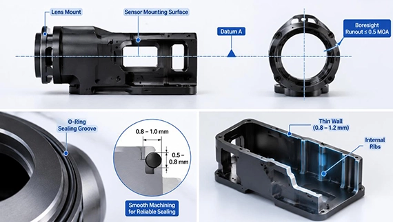
If the lens mounting shoulder, sensor locating surface, and other critical optical features do not share a unified datum system, their positional relationships may be difficult to control accurately. This is particularly problematic when parts require multiple setups with repeated repositioning or when different assembly surfaces are used as measurement references, as positional errors can accumulate. The resulting issues may include misalignment between the lens and detector, boresight deviation, and even reduced image quality or inaccurate equipment calibration.
Tips:
Thin-Wall Structural Design: Avoiding Manufacturing Risks Introduced by Lightweight Components
To reduce equipment weight, some night vision and thermal imaging enclosures use thin walls and deep internal cavities. If wall thickness changes abruptly or sufficient structural support is lacking, parts may experience localized warping, wall deformation, or dimensional deviations after machining. Long, narrow thin-wall cavities may also lack sufficient structural rigidity, resulting in vibration during machining, reduced surface quality, and even problems with subsequent assembly fits.
Tips:
Surface Treatment Tolerance Compensation: Preventing Scrap of Precision Threads and Small Holes After Finishing
After anodizing or other surface treatments, coatings on aluminum alloy enclosure can change the actual dimensions of the parts. If coating thickness and dimensional compensation are not considered during the design stage, precision holes and threads that originally meet the machining drawing requirements may become dimensionally out of specification after finishing. For example, anodizing buildup inside internal threads may make them tighter, causing screws to become difficult to install, bind during assembly, or even become impossible to thread in. For precision mating holes, coating thickness variations may also reduce the actual clearance and affect assembly.
Tips:
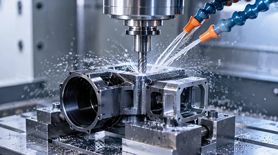
For CNC night vision and thermal imaging housing machining, manufacturing costs can be optimized through proper structural design, rational tolerance allocation, and the use of near-net-shape components.
1. Rationalize Tolerance Requirements
Apply tight tolerances of ±0.01 mm only to critical features such as optical axis locating holes. For non-critical areas, including non-mating cavities, cosmetic chamfers, and anti-slip patterns, tolerances can be relaxed to ±0.1 mm or even ±0.2 mm, depending on their functional requirements.
Avoid applying high-precision tolerances uniformly to all dimensions. This helps reduce finishing operations, machine time, and unnecessary quality inspection costs.
2. Optimize Internal Floor and Sidewall Corner Radii
Sharp internal corners are among the features that can significantly increase CNC milling costs.
During the design stage, maximize internal cavity corner radii where possible. The R value should be determined based on cavity depth and tool dimensions. Using larger-diameter standard end mills whenever possible helps avoid the need for miniature cutting tools or additional electrical discharge machining (EDM) operations to remove sharp internal corners.
3. Control Cavity Depth-to-Width Ratio
Where the structure allows, it is recommended to keep cavity depth within three times the tool diameter (≤3D).
When the depth-to-width ratio exceeds 5D, increased tool overhang reduces tool rigidity and makes deflection and machining vibration more likely. This typically requires reduced cutting parameters and longer machining times, increasing the manufacturing cost per part.
4. Sacrificial Clamping Tabs
Consider adding sacrificial clamping tabs (Lugs) in non-critical areas of the housing blank or structural design to provide stable clamping positions for the machining supplier.
This can reduce repeated setups and alignment operations for complex-shaped components, allowing the supplier to machine multiple faces more efficiently. The clamping features can then be removed in a final auxiliary operation, reducing setup labor and machining time.
5. Standardize Tooling
Standardize chamfer dimensions, thread specifications, and commonly used tool sizes across different hole locations whenever possible.
For example, provided structural strength and assembly requirements are met, using M2.5 and M3 fasteners consistently throughout the housing can reduce the frequency of tool and tap changes, minimize tool change time, and improve batch production efficiency.
6. Prioritize Extruded Profiles as Machining Blanks
For cylindrical night vision equipment housings, you can consider a near-net-shape manufacturing approach combined with CNC machining. Evaluate whether thick-wall seamless aluminum tubes or custom aluminum extrusions with dimensions close to the final housing geometry can be used as machining blanks.
Compared with removing large amounts of material from a solid aluminum billet, this approach reduces rough machining allowances, shortens machining time, and minimizes material waste, thereby lowering overall manufacturing costs.
1.Multi-Datum Machining: Maintaining Boresight Alignment Between the Objective Lens, Sensor, and Mounting Rail
Optoelectronic Machining Challenges:
Night vision devices and vehicle-mounted infrared sights typically include an objective lens bore, an FPA sensor mounting position, a rear eyepiece interface, and a Picatinny mounting rail.
Machining these features in separate setups can cause datum and positioning errors to accumulate, affecting concentricity, parallelism, and positional accuracy. This may ultimately compromise boresight stability, with deviations becoming more noticeable at longer observation distances.
Manufacturing Process Controls:
2.Vibration-Controlled Fixturing for Thin-Wall Lens Barrels: Reducing Chatter Marks
Optoelectronic Machining Challenges:
To reduce weight, some night vision housing walls are only 0.8–1.2 mm thick and may include asymmetrical features such as battery compartments and recessed button pockets.
These thin sections are prone to vibration during high-speed milling, causing chatter marks, poor surface quality, and possible deformation or roundness deviations in lens mounting bores.
Manufacturing Process Controls:
3. Toolpath Control for Nitrogen-Filled Sealing Interfaces: Preventing Radial Tool Marks
Optoelectronic Machining Challenges:
Some thermal imaging devices are evacuated and filled with dry nitrogen or argon to reduce internal fogging.
Improper reciprocating milling across sealing faces may leave tool marks crossing the O-ring groove, creating potential microscopic leak paths and compromising airtightness and IP68 protection.
Manufacturing Process Controls:
4. Fine Optical Threads and Light-Trapping Structures: Tolerance Compensation and Masking Before Surface Treatment
Optoelectronic Machining Challenges:
Night vision lens focusing rings often use M30–M50 fine-pitch threads, including 0.5 mm and 0.75 mm pitches. Housing interiors may also feature anti-reflective grooves to suppress stray light.
Excessive hard anodizing thickness can reduce thread clearance, making assembly difficult or causing threads to seize. Thick coatings may also cover internal light-trapping features and reduce their effectiveness.
Manufacturing Process Controls:
5. FPA Sensor Contact Surface: Controlling Flatness and Thermal Conductivity
Optoelectronic Machining Challenges:
The back of a thermal imaging sensor core typically contacts the housing's internal heat-dissipating base.
Poor mounting-surface flatness can cause uneven contact pressure and reduce heat transfer efficiency. Uneven temperature distribution may affect system stability and introduce thermal drift or fixed-pattern noise.
Manufacturing Process Controls:
6.Specialized Metrology and Leak Testing for Optoelectronic Equipment (Optomechatronic Inspection)
Optoelectronic Machining Challenges:
Unlike conventional mechanical parts, optoelectronic housings require not only dimensional inspection but also verification of spatial relationships between critical features and sealing performance under demanding environmental conditions.
Calipers and general-purpose measuring tools alone are often insufficient for comprehensive quality verification.
Manufacturing Process Controls:
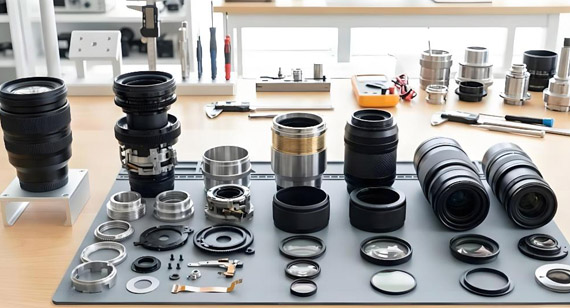
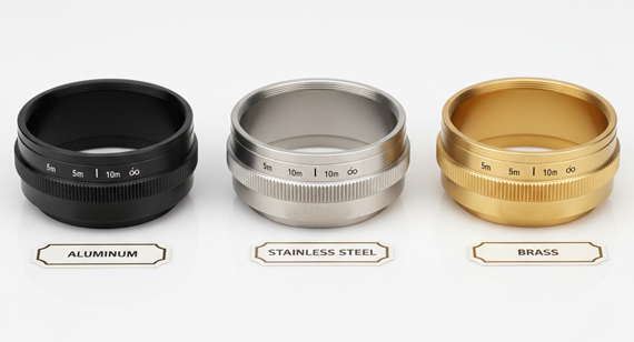
High-Precision, High-Volume Production of Camera Lens Rings and Optoelectronic Sensor Housings
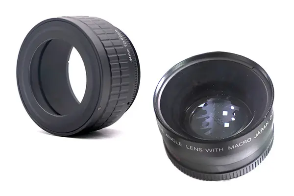
The project involved aerospace-grade AL6063-T6 camera lens housings requiring high concentricity and precision assembly. At peak production, output exceeded 3,000 units per day.
The Client's Challenges
Before working with us, the client had tested six CNC suppliers. However, none could consistently meet the required machining and assembly standards. Three key issues affected sample quality and delayed product development:
Our Engineering Solutions
To address these issues, we focused on coating compensation, fixture design, machining stability, and inspection consistency.
Project Results
The optimized process helped the client move from repeated sample failures to stable batch production.
The machining of precision night vision and thermal imaging housings ultimately tests a CNC manufacturer's engineering understanding of optomechanical structures, dimensional tolerances, and real-world operating environments. From micron-level tolerances specified on engineering drawings to maintaining stable imaging performance in demanding outdoor conditions, every stage requires careful process planning, precision machining, and strict quality control.
The success of a high-performance thermal imaging product depends not only on the design of its optical system, but also on the ability to consistently and accurately translate the geometric tolerances, assembly relationships, and structural requirements on engineering drawings into production-ready components.
Are you experiencing low production yields due to tolerance issues with custom CNC-machined night vision or thermal imaging housings, or looking for ways to optimize machining costs? Contact our engineering team and upload your drawings and project details. We will respond within 24 hours with a free Design for Manufacturability (DFM) review and a reliable quotation. [ We support 2D Drawings (PDF files), 3D Drawings (IGS/STP/STEP files)].
Send your 2D drawings, 3D CAD models, material, optical datum requirements, sealing requirements, critical tolerances, wall thickness, surface finish, prototype quantity and production quantity. VMT will review DFM, optomechanical datum planning, thin-wall machining, coating allowances, sealing interfaces, inspection and quotation requirements.
All information and uploaded files are secure and confidential.
1 Tell us what you need
2 Get solution & quote
3 Approve production
Email: inquiry@vimetal.com.cn
Q1: What is the typical lead time for custom CNC night vision housing prototypes?
A:Prototyping typically takes 3 to 7 business days, depending on geometry complexity and surface finishing requirements. If standard 6061-T6 aluminum and basic black anodizing are selected, rapid first-article parts can be delivered in as fast as 72 hours using 5-axis single-setup machining.
Q2: Why does an optical housing pass all CMM checks individually but fail optical axis alignment upon assembly?
A:This is almost always caused by Datum Misalignment (Tolerance Stack-up). If the lens mount and the sensor interface are machined using different coordinate setups, the geometric runout between them accumulates—even though each feature is within its own isolated linear tolerance. Machining both interfaces in a single 5-axis setup solves this issue fundamentally.
Q3: Is hardcoat anodizing strictly necessary for commercial thermal imaging bodies?
A:Not always. Type III is critical for military/tactical applications requiring high surface hardness (60+ HRC) and scratch resistance. However, for indoor industrial thermography or stationary security cameras, Type II Anodizing (thickness 8–12μm) or durable powder coating is often sufficient, easier to control in terms of dimensional tolerances, and reduces production costs by 15–20%.
Q4: How thin can the wall of an aluminum night vision housing be machined without severe warping?
A:Whie walls as thin as 0.5mm can theoretically be machined, we recommend a minimum wall thickness of 0.8mm to 1.2mm for structural integrity and stable sealing. Machining walls below 0.8mm drastically increases cycle time, requires customized damping fixtures to suppress high-frequency chatter, and significantly raises scrap risk.
Q5: Can CNC machining achieve the required surface finish for hermetic O-ring sealing without manual polishing?
A:Yes. Modern CNC milling using ultra-fine ball-nose or face-milling tools with optimized stepover parameters can reliably produce an Ra 0.4 to Ra 0.8μm surface finish directly off the machine. Manual polishing is actually discouraged, as it can introduce uneven waviness across the sealing plane that ruins hermetic (IP68) containment.
Q6: What critical documentation should we request from an optical housing machine shop for quality assurance?
A:A qualified supplier should provide: 1) Material Test Reports (MTR / Mill Certs) verifying alloy composition; 2) Full CMM Dimensional Inspection Reports (FAI) covering all geometric datums; 3) Anodizing/Coating Thickness Certificates; and optionally 4) Pressure Decay Leakage Test Reports for sealed enclosures.
The technical information and manufacturing advice shared on the VMT website are for general guidance only. While we strive for accuracy, VMT does not guarantee that the processes, tolerances, or material properties mentioned are applicable to every specific project. Any reliance you place on such information is strictly at your own risk. It is the buyer's responsibility to provide definitive engineering specifications for any production orders. Final specifications and service terms shall be subject to the formal contract or quotation confirmed by both parties.


 +86 15099911516




 Read more