16 years one-stop China custom CNC machining parts factory

Hey there I’m VMT Sam!
With 25 years of CNC machining experience we are committed to helping clients overcome 10000 complex part-processing challenges all to contribute to a better life through intelligent manufacturing. Contact us now
 111 |
Published by VMT at Nov 04 2026 | Reading Time:About 8 minutes


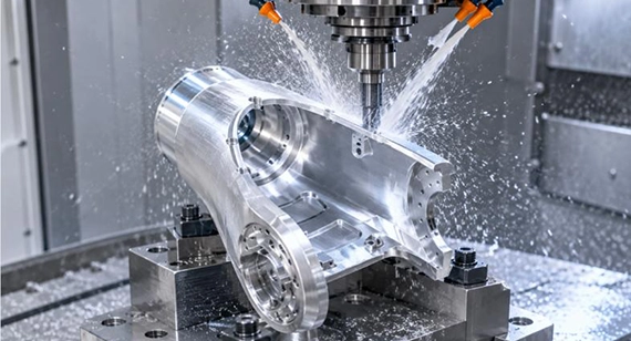
Precision manufacturing of robotic joint housings should not focus solely on the dimensional accuracy of individual components. It also requires establishing a unified datum system centered on the main rotational axis from the design stage, as well as evaluating the manufacturer's machining experience and capabilities. For example, manufacturers should adopt one-setup multi-axis machining whenever possible to minimize cumulative errors caused by repeated repositioning. Only by aligning design datums, machining accuracy, and assembly requirements can alignment deviations and assembly rework risks be effectively reduced.
Meeting dimensional requirements for individual interfaces on a robotic joint housing does not necessarily guarantee successful overall assembly. In actual production, joint binding, eccentricity, and insufficient rotational accuracy are rarely caused by a single out-of-tolerance dimension. In most cases, they result from datum misalignment, residual stress release after thin-wall machining, and tolerance stack-up across multiple interfaces.
This article focuses on five critical interfaces and design recommendations for custom CNC machined robotic joint housing & components, the importance of datum systems, and recommendations for evaluating suppliers. At the end of the article, we also share a case study showing how our factory solved a roundness deviation issue in a 6061 aluminum high-speed micro motor housing, achieving zero-binding, adjustment-free bearing assembly, delivering 60,000 units within 35 days, and reaching a 98.8% production yield.
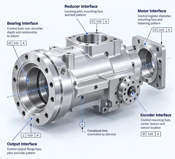
Robotic joint housings typically contain multiple precision mounting and locating interfaces. Each serves a specific function, including bearing support, reducer positioning, motor installation, signal detection, and load transmission. During design, it is important to consider not only the dimensional tolerances of individual interfaces but also the datum relationships, mating accuracy, and machining feasibility between them. The following sections introduce five key interfaces, along with their design considerations and tolerance control recommendations:
1. Bearing Interface: Preventing Local Binding
The bearing interface directly affects bearing fit, rotational accuracy, and operating stability. The fit tolerances between the bearing bore and shaft journal should be selected based on the bearing type and operating conditions, with precision grades such as H6/h5 as a reference.
An undercut or relief groove should be provided at the root of the bearing mounting shoulder to prevent interference between CNC-machined corner radii and the bearing end face, ensuring proper seating. In addition to controlling bore diameter tolerances, engineering drawings should specify the circular runout of the bearing bore relative to the common datum axis to ensure alignment between the bearing mounting position and the rotational axis.
2. Reducer Interface (Harmonic/RV): Removing Sources of Eccentricity
The reducer interface achieves precise positioning primarily through a locating register (Spigot/Pilot Register) and a mounting face. The perpendicularity between the locating register and mounting face should be controlled within ≤0.008 mm to prevent eccentricity or tilting after reducer installation. What’s more, the bolt hole pattern (PCD) should preferably use Maximum Material Condition (MMC) tolerancing. The positional tolerance of fastening holes can be appropriately relaxed while maintaining assembly requirements, allowing the locating register to serve as the primary positioning feature.
3. Motor Interface (Stator/Rotor Interface): Ensuring Dynamic Concentricity
The motor interface mainly involves the stator mounting cavity and rotor bearing seat. Their concentric relationship directly affects motor air-gap uniformity and operating stability. During design, the stator mounting cavity and rotor bearing seat should be defined as related features within the same datum system to ensure their relative positional accuracy. Thin-walled motor housings must also account for thermal expansion caused by operating temperature changes, with fit clearances or interference levels evaluated under different temperature conditions.
4. Encoder Interface: Ensuring Signal Detection Accuracy
The encoder interface is primarily used to mount and secure the angular position sensor. The flatness and positioning accuracy of its mounting surface directly affect the sensor's installation alignment. For mounting surfaces adjacent to precision sensors, a surface roughness of Ra 0.8 or better is recommended to prevent minor burrs or surface irregularities from causing sensor tilt. The housing design should also include dedicated cable routing grooves for strain relief and anti-static chamfers.
5. Output Flange-to-Arm Interface: Ensuring Rigid Load Transmission
The output flange transmits torque generated by the robotic joint to the robot arm. Its end-face accuracy directly affects connection stability and load transmission.
During design, end-face flatness is essential for ensuring proper contact between mating surfaces and resisting overturning moments. For high-torque robotic joints, locating dowel pins are recommended to help share the shear loads otherwise borne by the fastening bolts, improving connection stability.
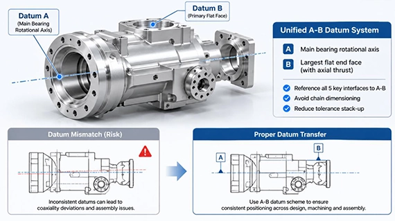
Even if individual interfaces on a robotic joint casing pass dimensional inspection, this does not guarantee accurate relative positioning after assembly. The problem often stems from inconsistent datums across design, machining, and assembly, causing errors to accumulate and ultimately affecting bearing alignment, reducer positioning, and overall rotational accuracy.
1. Datum Mismatch: Geometric Errors Caused by Inconsistent Datums
In actual manufacturing, the design datum (drawing centerline), machining datum (CNC positioning origin), and assembly datum (bearing rotational axis) may not be aligned. This can lead to positional deviations between interfaces.
Even when individual interface dimensions meet drawing requirements, the assembled unit may still exhibit coaxiality deviations, mounting face misalignment, or bearing fit issues, affecting the overall operating accuracy of the robotic joint.
2. Datum Transfer Chain: Establishing a Unified Reference System
Core Principle: Define the main bearing rotational axis as Primary Datum A, and the largest flat end face that withstands axial thrust as Secondary Datum B.
Geometric tolerances, including position and coaxiality, for all five key interfaces of the robotic joint housing should reference the unified A-B datum system as consistently as possible. This ensures consistent positioning references across design, machining, and assembly.
At the same time, engineering drawings should avoid chain dimensioning wherever possible and instead use datum-based coordinate dimensioning. This reduces tolerance accumulation caused by sequential dimension transfers and helps maintain the relative positional accuracy between interfaces.
Mechanical binding in robot joints is often related to the alignment of the two bearing mounting bores. In a rotary structure supported by two bearings, even a slight angular misalignment between the bore axes can create a V-shaped offset. Once the bearings are installed, this misalignment constrains the relative positions of the inner and outer rings, resulting in uneven load distribution between the rolling elements and raceways and increased localized contact stress. If the axial preload is also excessive, bearing rotational resistance may increase further, potentially causing the joint to seizure during operation.
Tips: The coaxiality requirement for the two bearing bores should be clearly specified in the structural design and engineering drawings. Both bores should be treated as related critical locating features and controlled within the same datum reference system. The design requirements should also specify that the two bearing bores be line-bored in one clamping setup (Line Boring in One Clamping) to minimize centering errors caused by repeated positioning.
In addition, adequate tool-relief clearance should be provided at the base of each bearing mounting shoulder. This prevents fillets in the transition areas from interfering with the bearing outer rings and ensures that the bearing end faces seat fully against their locating surfaces. This helps reduce the impact of localized contact issues on bearing performance.
Eccentric assembly primarily involves a mismatch between the rotational centers of the reducer and the motor. When the reducer locating pilot and the motor input shaft are not concentric, radial misalignment may occur between the motor output shaft and the reducer input, resulting in uneven gear meshing.
During continuous joint operation, this eccentricity may cause periodic noise, vibration, and localized heat generation. If the misalignment persists, it can also increase localized loads on the gear teeth and accelerate wear. In severe cases, it may even lead to tooth breakage, compromising the transmission stability of the entire joint.
Tips: During the DFM (Design for Manufacturability) stage, consider integrating the motor adapter flange and the reducer front housing into a single structure (Integrated Housing). Reducing the number of physical interfaces between separate parts can minimize the effects of interface positioning errors and tolerance stack-up, helping prevent potential eccentricity at the structural design stage.
If a separate connection structure is required, the datum relationship between the reducer locating pilot and the motor input shaft should be clearly defined to ensure that the two rotational centers remain aligned by design.
Alignment rework and excessive shimming are often related to the geometric accuracy of mounting faces and the structural rigidity of connection areas. When the perpendicularity or flatness of a robot joint housing's mounting face is out of tolerance, the mating components may not seat properly. Uneven bolt clamping forces can also cause localized deformation of the mating surfaces, shifting the assembly position from its intended alignment.
During assembly, these deviations often need to be corrected by manually adding shims to level and align the components. This not only increases assembly time but also reduces consistency between production batches, making stable high-volume production more difficult.
Tips: Key mounting-face geometric tolerances should be carefully controlled during the design stage, particularly flatness (Flatness ≤0.005 mm) and perpendicularity. This helps ensure proper contact between mating surfaces and minimizes the impact of face errors on overall assembly alignment.
For thin-walled robot joint housings, particular attention should also be paid to the local structural rigidity around bolted connections. Localized wall thickening or reinforcing ribs (Rib Design) can be added around these areas to improve support stiffness. This helps prevent minor contact-surface deformation caused by bolt tightening torque and reduces the need for manual shimming during assembly.
When finding a custom cnc machined robot joint housings supplier, it is important to look beyond the number of machines or inspection results from individual samples. Greater attention should be paid to the supplier's precision manufacturing capabilities, process control, quality inspection, and ability to support consistent batch production and delivery. The following five capabilities are key indicators of a supplier's overall manufacturing strength:
1. Multi-Axis Machining and Fixturing Capability (Multi-Axis Capability)
Priority should be given to suppliers equipped with high-precision five-axis machining centers, such as DMG MORI or Mikron machines, or horizontal machining centers (HMCs). Their fixturing strategies should also be evaluated to determine whether they can minimize repositioning errors between the motor cavity, reducer cavity, and bearing seats, thereby improving geometric consistency across critical interfaces.
2. Stress Control and Process Planning
Suppliers should have a well-defined process plan and stress-control procedure covering rough machining, stress-relief treatment, semi-finishing, and final finishing. For thin-walled robot joint housings, particular attention should be paid to deformation control at each stage to minimize the impact of residual stress on final dimensional stability.
3. Dedicated Fixturing Solutions for Thin-Walled Components
Suppliers should have the capability to design and develop dedicated fixturing solutions, such as soft jaws, pneumatic mandrels, or vacuum fixtures. Proper fixture design helps distribute clamping forces more evenly, improve positioning stability, and reduce deformation of thin-walled structures during clamping.
4. Metrology and Quality Inspection Capabilities (Metrology Equipment)
Suppliers should be equipped with high-precision coordinate measuring machines (CMMs), such as ZEISS systems with measurement accuracy of ≤1.5 μm. Their precision inspection areas should also maintain stable temperature-controlled conditions, for example, 20±0.5°C, to minimize the impact of temperature variations on measurement results.
5. Process Capability and Batch Production Consistency
For critical dimensions and functional features, the process capability index (Cpk) should consistently reach ≥1.33. Suppliers should also provide quality data from ongoing production to demonstrate their ability to maintain dimensional control, minimize batch-to-batch variation, and support stable volume production.
Solving Roundness Issues in 6061 Aluminum High-Speed Micro Motor Housings to Achieve Zero-Binding, Adjustment-Free Bearing Assembly and Deliver 60,000 Units in 35 Days with a 98.8% Yield Rate
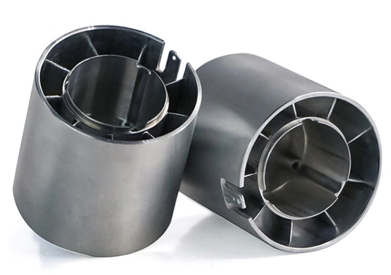
A client in the robotics industry approached us to manufacture ultra-thin-walled 6061-T6 aluminum alloy micro brushless motor housings for high-end collaborative robot joints. The parts had an outer diameter of Φ45 mm and an overall length of 60 mm, with a wall thickness of just 1 mm. Despite the thin-wall structure, critical dimensional tolerances had to be maintained within 8 μm, with concentricity controlled within 0.01 mm. Since precision bearings and rotating components are installed inside the motor housing, dimensional deviations can affect bearing fit and increase vibration and noise during rotation. Therefore, the relative positioning accuracy between concentric features had to be strictly maintained throughout machining.
However, the client's previous supplier had struggled with roundness control, with measured roundness deviation reaching 0.03 mm. This caused binding during bearing assembly and required additional manual fitting. Dissatisfied with the machining quality, the client sought a new supplier capable of consistently controlling precision in thin-walled structures.
1. Problem Analysis: Why Did the Thin-Walled Motor Housing Deform After Machining?
Our analysis indicated that the problem was most likely related to the previous supplier's machining process and workholding method. The previous supplier used solid round-bar stock and directly machined the internal cavity through CNC hollowing. Removing large amounts of material in a short period released internal residual stresses, causing deformation in the thin-walled structure. At the same time, the rigid clamping method of a conventional three-jaw chuck introduced another problem. For an aluminum housing with a wall thickness of just 1 mm, concentrated clamping forces at three points could cause localized elastic deformation, resulting in a typical issue: The workpiece appeared round while clamped, but became slightly oval after unclamping, with roundness deviation reaching 0.03 mm.
2. Our Solution: Optimizing the Blank, Fixture, and CNC Finishing Process
Considering the material properties of 6061-T6 aluminum and the sensitivity of the 1 mm thin-wall structure to machining stress and clamping forces, we focused on optimizing three key areas.
(1) Redesigning the Blank Forming Process to Reduce Material Removal and Residual Stress
We replaced the original solid round-bar machining approach with a near-net-shape blank followed by CNC precision machining. By optimizing the blank structure and material removal volume, we reduced unnecessary cutting operations and minimized the risk of stress release and thin-wall deformation caused by extensive material removal.
(2) Redesigning the Workholding Fixture to Prevent Thin-Wall Deformation
Our engineering team replaced the conventional three-jaw chuck with a full-wrap flexible slotted collet, combined with a custom internal expanding mandrel. This fixture distributes clamping forces evenly around the full 360° circumference, reducing localized stress concentrations caused by conventional three-point clamping. Clamping force and support positions were also carefully controlled to minimize elastic deformation during machining. This approach maintained workpiece stability during machining while reducing the risk of roundness changes after unclamping.
(3) Optimizing the Machining Sequence and Cutting Parameters to Maintain Final Dimensional Stability
During CNC machining, we separated roughing and finishing operations and reserved a finishing allowance of 0.15 mm. After rough machining, a secondary natural stress-relief period was introduced to allow further release of internal residual stresses before final finishing. For bearing mating surfaces and critical concentric features, we used custom ultra-fine-grain PCD (polycrystalline diamond) cutting tools at a spindle speed of 18,000 RPM with light cutting passes, reducing cutting forces and heat generation that could affect the thin-wall structure. We also optimized the finishing sequence, prioritizing critical bearing seats and concentric datum features to prevent excessive localized material removal from compromising overall geometric accuracy.
3. Final Results: Reliable Assembly and High-Volume Production Delivery
After first-article validation, the client approved the optimized machining process and product quality. During subsequent mass production, the process effectively resolved the roundness deviations and assembly binding issues experienced with the previous supplier:
Custom CNC machined robot joint housings projects ultimately needs to be validated through actual assembly and operational performance. Even when critical dimensions meet drawing requirements, attention must still be paid to bearing installation, reducer meshing, rotational resistance, and the fit of each connecting interface. Therefore, during project development, you should combine dimensional inspection of critical interfaces with actual assembly validation and identify potential fit issues as early as possible during the prototype stage. For batch production, you should also continuously monitor critical dimensions, assembly results, and process capability data to ensure that the precision validated during prototyping can be consistently maintained throughout mass production.
Are you currently experiencing issues with roundness, eccentricity, binding during assembly or operation, or poor alignment between interfaces and datums in your CNC machined robot joint housings and related components? Contact us and let our engineering team review your drawings with a free design for manufacturability (DFM) assessment, along with custom machining solutions and an accurate quotation. [ We support 2D Drawings (PDF files), 3D Drawings (IGS/STP/STEP files)].
Send your 2D drawings, 3D CAD models, material, bearing and reducer interface requirements, datum scheme, critical tolerances, wall thickness, surface finish, prototype quantity and production quantity. VMT will review DFM, datum relationships, multi-axis machining strategy, thin-wall deformation control, fixturing, inspection and quotation requirements.
All information and uploaded files are secure and confidential.
1 Tell us what you need
2 Get solution & quote
3 Approve production
Email: inquiry@vimetal.com.cn
Q1: When balancing robotic joint assembly accuracy with costs, what are common tolerance overdesign mistakes?
A:You may specify utra-tight tolerances of ±0.005 mm for every interface. However, a more effective cost-control method is to apply tight tolerances only to critical mating features, such as bearing seats and reducer locating bores, while allowing wider tolerances for non-mating areas, such as housing profiles and non-locating end faces (typically ±0.02–0.05mm). This approach maintains assembly accuracy while reducing CNC machining time and associated costs by approximately 25%–40%.
Q2: How to prevent situations where CMM inspection results indicate compliance, but actual assembly still experiences binding ?
A:The root cause often lies in the difference between measurements taken under free-state and constrained-state conditions. Thin-walled housings may undergo elastic deformation under CMM probe contact forces, while clamping during inspection can introduce artificial stress and distort measurement results.The factory should have standardized CMM fixturing procedures and use low-force probe systems. Functional Go/No-Go gauges should also be used as a physical verification method to confirm actual mating conditions and assembly compatibility.
Q3: How do surface treatments such as anodizing affect micron-level interface tolerances, and how can they be compensated for?
A:Standard anodizing produces a coating thickness of approximately 5–15 μm, while hard anodizing can reach 25–50 μm (approximately 50% grows outward and 50% penetrates inward). Before machining, appropriate coating allowances must be reserved in the CNC machining program for precision bearing seats. Alternatively, for critical H6-tolerance bores, drawings should specify "Dimensions Apply After Anodizing", or dedicated silicone plugs should be used to mask threads and datum holes before anodizing.
Q4: When robotic joint housing walls are thinner than 1.5 mm, what material stress-relief measures are essential beyond fixture design?
A:In addition to fixture design, thermal or vibratory stress-relief processes should be incorporated into the CNC machining process. Large housings can undergo stress-relief annealing after rough machining. Meanwhile, a symmetrical, multi-layer high-speed milling strategy (Trochoidal Milling) should be adopted to keep material removal rates balanced on both sides of the part, preventing asymmetric internal residual stresses caused by excessive cutting on one side.
Q5: Why do threaded connections in robotic joint housings directly affect the alignment of precision rotary mechanisms?
A:Bolt tightening generates significant axial preload and localized compressive stress on mating surfaces. If threaded holes are too shallow, lack entry chamfers, or have axes that are not perpendicular to the mounting face, tightening can cause localized micron-level surface bulging (Puckering/Bulging), tilting the reducer mounting face and compromising alignment. High-precision self-locking inserts (such as Keensert) are recommended, along with proper perpendicularity of the threaded pilot holes.
Q6: What are the differences in tolerance control between aluminum (6061/7075), high-rigidity titanium and SS when machining robotic joint housings?
A: 6061-T6: Offers good ductility and machinability, but is more susceptible to cutting-induced stress deformation and has poor dimensional stability in thin-walled structures. 7075-T6: Offers higher rigidity and a denser internal grain structure than 6061, making it easier to maintain micron-level concentricity. It is a preferred choice for high-performance, lightweight robotic joints.
Titanium Alloys / Stainless Steel: Their low thermal conductivity and different elastic properties make thermal expansion and contraction during machining important factors affecting dimensional tolerances. When machining titanium alloy joint housings, strict temperature control and consistent coolant cooling are essential. Otherwise, a part that passes inspection immediately after machining may experience significant hole diameter shrinkage and fall out of tolerance after returning to room temperature.
Q7: What Types of Robot Joint Housings and Components Can I Soucing?
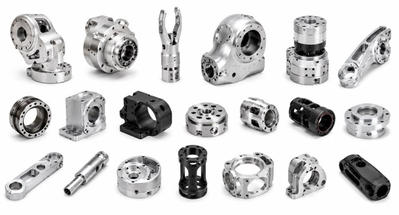
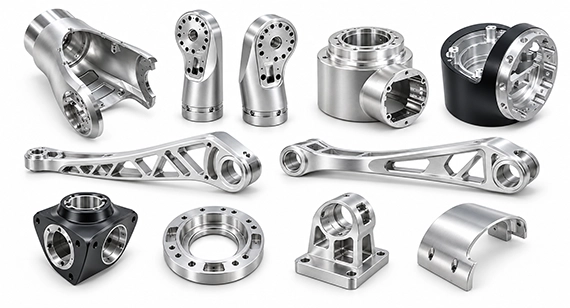
We provide custom CNC machining for a range of robot joint housings and components,including Frameless BLDC Motor Housings, Harmonic Drive Cup / Spline Housings, Cycloidal Speed Reducer Housings, Rotary Actuator Enclosures, Robot Arm Joint Modules, and Integrated Joint Housings (Unibody Housings). Parts can be manufactured to your drawings and specific requirements for dimensional accuracy, interface alignment, and assembly fit.
The technical information and manufacturing advice shared on the VMT website are for general guidance only. While we strive for accuracy, VMT does not guarantee that the processes, tolerances, or material properties mentioned are applicable to every specific project. Any reliance you place on such information is strictly at your own risk. It is the buyer's responsibility to provide definitive engineering specifications for any production orders. Final specifications and service terms shall be subject to the formal contract or quotation confirmed by both parties.


 +86 15099911516



 Read more