16 years one-stop China custom CNC machining parts factory

Hey there I’m VMT Sam!
With 25 years of CNC machining experience we are committed to helping clients overcome 10000 complex part-processing challenges all to contribute to a better life through intelligent manufacturing. Contact us now
 0 |
Published by VMT at Oct 24 2026 | Reading Time:About 6 minutes


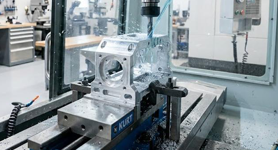
The precision and dimensional stability of CNC machined camera mounts are vital to the image quality of your action cameras, automotive photography setups, drone cameras, and industrial inspection systems. CNC machining perfectly preserves the raw strength and anti-vibration properties of high-end materials like aerospace-grade Aluminum 7075 or stainless steel, achieving high precision tolerances ranging from ±0.005mm to ±0.01mm. However, in actual custom production, thin-wall deformation, hole misalignment, and dimensional changes caused by surface treatments can indeed be frustrating.
This article will provide comprehensive guidance and practical tips to avoid pitfalls by exploring common types of CNC machined camera mounts, material comparisons, typical manufacturing issues with design recommendations, and suggestions for auditing suppliers. At the end of the article, we will also share a case study detailing how our CNC machining facility solved thin-wall deformation issues for a camera industry client and achieved a precision of ±0.01 mm with a 99.2% yield rate for custom aluminum fork mounts.
CNC machining uses computer-programmed tool paths to precisely cut and finish custom camera mounts and brackets from solid blocks of material, ensuring high repeatability. Thereby, CNC machined camera mounts and brackets are precision-engineered hardware components produced through precision subtractive manufacturing processes, designed to provide exceptional structural strength, dimensional accuracy, and vibration resistance for various camera systems.
Advantages of CNC machining for Camera Mounts
The core advantages of utilizing CNC machining for camera mounts include:
Types of CNC Camera Mounts and Accessories
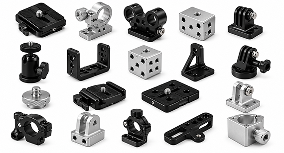
Types of Custom CNC Camera Mounts and Accessories that You Can Design or Source Include:
CNC Mounts by Camera Types:
CNC Mounts or Brackets by Shapes and Configurations:
In theory, the advantages of CNC machining for camera mounts mentioned above can be fully realized by an experienced manufacturer. However, in reality, the supplier you choose may cause production issues due to a lack of experience, technician skill levels, or lax quality control—resulting in defective parts, rework costs, and project delays. Therefore, supplier qualifications require careful auditing on your part.
Below are some common problems our previous clients encountered with their former suppliers, along with design and engineering considerations you can apply to custom camera mounts to avoid these issues:
1. Loosening or Camera Shaking
Fork spacing, mounting surfaces, locking structures, pins, and threaded interfaces must work together.
How to Ensure Integration (Engineering Recommendations):
Designs and Practices That Impair Integration:
2. Hole and Thread Misalignment
Hole positioning, thread depth, bracket perpendicularity, and mounting alignment directly impact assembly forces and camera stability.
Pitfalls and Value Recommendations:
3. Thin-Wall Deformation
Lightweight camera brackets typically feature thin arms, deep pockets, and small radius fillets.
Design and Engineering Recommendations:
4. Post-Processing Dimensional Changes
Anodizing, powder coating, and plating alter fit dimensions, thread engagement, and surface appearance.
Recommendations and Callouts on Drawings:
Dimensional Allowances and Drawing Callouts:
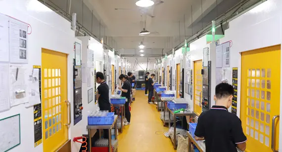
To consistently achieve the precision required for custom CNC camera mounts and brackets, you should evaluate a supplier not only on their equipment list, but also audit their quality control procedures, engineering workflows, and machining practices.
A reliable camera mounts cnc machining factory should demonstrate the following core capabilities:
First, let us look at what your primary requirements are for CNC camera mounts and brackets:
(The materials recommended here are some of the most commonly chosen options. If you need to consult about other materials suitable for your project, please feel free to bring your primary requirements and specific material names to consult with us.)
Table 1: Core Physical and Mechanical Properties of These Materials
| Material | Appearance | Density (g/cm cubed) | Melting Point (Degrees Celsius) | Tensile Strength (MPa) | Yield Strength (MPa) | Rockwell Hardness | Elastic Modulus (GPa) | Corrosion Resistance | Electrical Insulation |
| Stainless Steel 303 | Metallic Silver | 8.00 | 1400 to 1420 | 620 | 240 | HRB 83 to 90 | 193 | Good | No (Conductor) |
| Stainless Steel 304 | Metallic Silver | 8.00 | 1400 to 1450 | 515 | 205 | HRB 70 to 90 | 193 | Excellent | No (Conductor) |
| Stainless Steel 316 | Metallic Silver | 8.00 | 1375 to 1400 | 580 | 290 | HRB 79 to 90 | 193 | Superior (Marine) | No (Conductor) |
| Aluminum 6061-T6 | Silvery White | 2.70 | 582 to 652 | 310 | 276 | HRB 60 (95 HB) | 68.9 | Good | No (Conductor) |
| Aluminum 7075-T6 | Silvery White | 2.81 | 477 to 635 | 572 | 503 | HRB 87 (150 HB) | 71.7 | Moderate | No (Conductor) |
| Titanium Grade 5 (Ti-6Al-4V) | Dark Metallic Gray | 4.43 | 1604 to 1660 | 950 | 880 | HRC 36 | 113.8 | Superior | No (Conductor) |
| Brass C36000 | Bright Golden | 8.50 | 885 to 900 | 390 | 180 | HRB 60 to 80 | 100 | Good | No (Conductor) |
| Bronze C54400 | Reddish-Gold | 8.89 | 930 to 1020 | 470 | 390 | HRB 75 to 85 | 110 | Excellent | No (Conductor) |
| POM (Delrin/Acetal) | Opaque White or Black | 1.41 | 165 to 175 | 65 | 60 | Rockwell R 120 | 2.8 | Excellent | Yes (Insulator) |
| PEEK | Beige, Light Brown or Black | 1.32 | 343 | 100 | 95 | Rockwell R 126 | 3.6 | Superior | Yes (Insulator) |
| PTFE (Teflon) | White | 2.20 | 327 | 20 to 35 | 10 to 15 | Rockwell R 50 | 0.5 | Exceptional | Yes (Insulator) |
Table 2: Surface Finishes and Production Cost Breakdown
| Material | Post-Finish Visual and Functional Effects | Machinability | Relative Material Cost | Relative Machining Cost |
| Stainless Steel 303 | Passivation: Enhanced rust protection Electropolishing: Smooth mirror finish Mechanical Polishing: Bright metallic shine PVD Coating: Premium colored wear-resistant surface |
Excellent | Moderate | Moderate |
| Stainless Steel 304 | Passivation: Standard anti-rust barrier Electropolishing: Clean deburred surface Bead Blasting: Uniform matte texture PVD Coating: Decorative durable color |
Good | Moderate | Moderate |
| Stainless Steel 316 | Passivation: Superior marine corrosion resistance Electropolishing: High-purity smooth finish PVD Coating: High-end industrial coating |
Fair | High | Moderate to High |
| Aluminum 6061 | Multi-Color Anodizing: Vibrant decorative colors Hard Coat Anodizing: Thick wear-resistant layer Bead Blasting: Soft matte finish Powder Coating: Protective thick colored shield |
Excellent | Low | Low |
| Aluminum 7075 | Hard Coat Anodizing: Maximum abrasion resistance Bead Blasting: Matte industrial appearance Laser Engraving: Permanent high-contrast markings |
Very Good | Moderate | Moderate |
| Titanium Grade 5 | Color Anodizing: Interference color enhancement PVD Coating: Extreme surface hardness Bead Blasting: Premium titanium matte texture Polishing: High-gloss metallic luster |
Poor | Very High | High |
| Brass C36000 | Nickel Plating: Tarnishing protection Polishing: High-gloss golden luster Clear Coating: Long-lasting vintage shine Passivation: Oxidation prevention |
Superior | Moderate | Very Low |
| Bronze C54400 | Polishing: Antique reddish-gold reflection Passivation: Surface film stabilization Clear Lacquer: Preserved natural metallic look |
Very Good | Moderate to High | Low |
| POM | As-Machined: Clean semi-matte plastic finish Mechanical Deburring: Smooth burr-free edges |
Excellent | Low to Moderate | Very Low |
| PEEK | As-Machined: Natural engineering plastic look Bead Blasting: Uniform matte texture |
Fair | High | Moderate to High |
| PTFE | As-Machined: Ultra-low friction non-stick surface Precision Trimming: Clean dimensional edges |
Poor (Soft) | High | Moderate |
Solving Thin-Wall Deformation and Achieving Plus/Minus 0.01 mm Precision for Custom Aluminum Fork Mounts
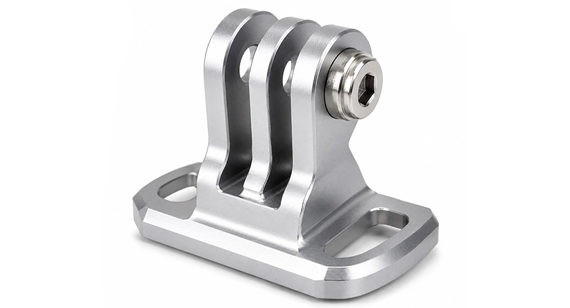
A camera accessory brand required custom aluminum fork mounts featuring threaded tripod interfaces, compact thin-wall arms measuring two millimeters, and a bead-blasted anodized finish for prototype validation and planned batch production.
Upon reviewing the sample batches produced by their previous supplier, two critical issues were identified:
Causes
Thin-walled components are susceptible to elastic or plastic deformation during CNC roughing and finishing due to cutting forces and the release of residual stresses. Furthermore, bead blasting using glass beads or abrasive grit introduces intense localized compressive stress to the material surface. If the blasting is uneven on both sides or if the wall thickness is less than two millimeters, the thin arms will bend like bimetallic strips.
The previous supplier likely omitted stress-relieving heat treatment between machining and surface finishing, failed to control blasting pressure, or neglected to use milder chemical polishing to achieve a matte texture. The fork gap and pivot hole misalignment were direct cascading geometric tolerance failures triggered by this structural distortion.
Our Engineering Solutions
To prevent these issues and meet the client product specifications, we implemented the following measures:
Final Results
By implementing these process controls and engineering solutions, our engineering team achieved outstanding results for the camera industry client:
Customizing CNC machined camera mounts requires matching your specific priorities, such as appearance, texture, corrosion resistance, and cost, among a wide range of materials like Aluminum 6061, aerospace-grade Aluminum 7075, stainless steel, or titanium alloys. It also tests your engineering trade-offs in design, alongside your chosen manufacturer's ability to control engineering details such as tolerance stack-ups, stress-relieving annealing, bead blasting pressure, and surface treatment masking. By utilizing the material and surface finish recommendations, common pitfall avoidance strategies, design tips, and manufacturer auditing advice in this article, you can better prevent issues like camera shaking, thread misalignment, and thin-wall deformation, ensuring the stability and durability of your camera mounts and brackets after assembly.
Looking for custom solutions for materials and surface finishes for CNC camera mounts and brackets, or needing assistance ranging from prototype validation to high-consistency batch production? Welcome to contact our engineering team. We will provide you with professional manufacturing feasibility assessments, optimal material selection advice, and competitive quotations to help successfully bring your camera products to market! [ We support 2D Drawings (PDF files), 3D Drawings (IGS/STP/STEP files)].
Send your 2D drawings, 3D CAD models, material, tolerance requirements, wall thickness, thread specifications, surface finish, prototype quantity and production quantity. VMT will review DFM, material selection, CNC machining, deformation control, coating allowances, inspection and quotation requirements.
All information and uploaded files are secure and confidential.
1 Tell us what you need
2 Get solution & quote
3 Approve production
Email: inquiry@vimetal.com.cn
1. What CNC machining processes are used for camera mounts and brackets?
2. Does the choice of CNC machining process affect my camera mount quotation?
Yes. Factories select processes based on your camera mount material, tolerance, and geometry to optimize cost and efficiency. Ranked by relative maching cost from highest to lowest (by minutes):
But this doesn’t mean 3-aix is more economical than 5 aix or others when maching complex shapes as the machining time and precision achievement(rework) is considered.
3. Why is masking needed for CNC camera mounts during surface finishing?
Masking is the process of covering specific functional areas, such as precision tripod screw threads, quick-release mating surfaces, and bearing seats, with high-temperature tape or plugs before anodizing or coating. It prevents coating buildup from ruining thread engagement and causing loose camera attachments.
4. What quality reports should I check when auditing a manufacturer for camera mounts?
5. How do qualified factories control thread and mounting interface fit for camera brackets?
They review thread specs, engagement lengths, fork gaps, and datum alignments before production. During inspection, they use thread gauges, pin gauges, coordinate measuring machines, and physical functional assembly checks using mating camera components.
6. What is the recommended surface roughness for camera mounts and does it affect cost?
The technical information and manufacturing advice shared on the VMT website are for general guidance only. While we strive for accuracy, VMT does not guarantee that the processes, tolerances, or material properties mentioned are applicable to every specific project. Any reliance you place on such information is strictly at your own risk. It is the buyer's responsibility to provide definitive engineering specifications for any production orders. Final specifications and service terms shall be subject to the formal contract or quotation confirmed by both parties.


 +86 15099911516




 Read more