15 years one-stop China custom CNC machining parts factory
 1440 |
Published by VMT at Dec 31 2024 | Reading Time:About 8 minutes
Are you tired of enduring excessive tool wear, inconsistent surface finishes, or prolonged machining times that drain resources and reduce profitability? Many manufacturers grapple with the complexities of choosing and setting the correct cutting depth in machining. The result is often shorter tool life, higher scrap rates, or compromised product quality—issues that can severely impact your bottom line and customer satisfaction. Fortunately, learning how to properly define and calculate the depth of cut (DOC) can resolve these challenges, allowing you to optimize cutting parameters, preserve cutting tools, and consistently achieve superior part accuracy. This comprehensive guide explores the essentials of cutting depth in machining, explaining its role, impact, and best practices for calculation, so you can empower your CNC machining factory to deliver top-tier CNC machining parts with optimal efficiency and quality.
The depth of cut in machining refers to the measurement between the uncut surface and the newly formed surface after a cutting pass. Properly defining and calculating the cutting depth enhances tool life, reduces heat buildup, and yields precise CNC machining parts. By following recommended guidelines, you can streamline custom CNC machining operations, minimize errors, and achieve uniform results in CNC prototype machining and full-scale production.
To fully understand why depth of cut is so critical, it’s essential to explore the fundamental concepts of DOC, its different types, and how it affects vital aspects of CNC machining services. By examining these components, you can make informed decisions and ensure that both your tool selection and machine parameters are aligned with your manufacturing goals. Let’s begin with a broad overview of how depth of cut is defined and categorized in modern machining processes.
Preface
In any machining process—be it turning, milling, drilling, or grinding—the depth of cut (DOC) is a fundamental parameter that significantly influences part quality, production costs, and overall efficiency. For CNC machining factory operations, the importance of choosing the correct DOC cannot be overstated. It determines how much material is removed in a single pass, which in turn affects cutting forces, tool life, surface finish, and machining cycle times. An improperly set cutting depth may lead to excessive tool wear, unnecessary heat generation, vibration, or even catastrophic tool failure.
Understanding DOC becomes even more critical when dealing with custom CNC machining projects, where varied designs and tolerance requirements demand meticulous parameter control. In industries such as automotive, aerospace, and medical device manufacturing, precision is paramount, and a miscalculation in cutting depth could result in reject parts or safety hazards. CNC machining parts must therefore be produced with unwavering accuracy, which demands strategic selection of feed rates, spindle speeds, and—most notably—depth of cut.
Beyond these technical aspects, an optimized DOC helps strike a balance between productivity and tool longevity. A deeper cut in a single pass might reduce cycle time temporarily but can risk tool overload, degrade surface quality, and result in higher tool replacement costs over time. Conversely, extremely shallow cuts might yield pristine finishes but drastically inflate production timelines and labor costs. Thus, machine shops that invest time in perfecting their approach to cutting depth in machining are far more likely to achieve consistent, high-quality results that bolster their reputation for reliability and efficiency. Whether you’re setting up a CNC prototype machining job or scaling up to mass production, the strategic management of DOC is indispensable for success.
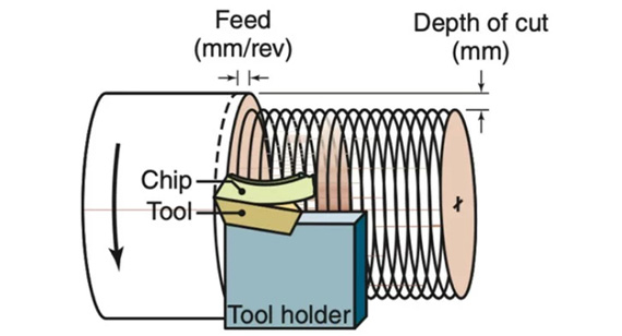
Depth of cut in machining is the distance from the unmachined workpiece surface to the newly machined surface after a single pass of the cutting tool. Essentially, it signifies how deeply the tool penetrates the workpiece during that pass, removing a specific layer of material. This metric is often expressed in millimeters (mm) or inches, and although it sounds straightforward, it holds significant ramifications for a machine’s performance and the final part quality.
In a typical scenario, a cutting tool like an end mill, drill bit, or turning insert engages the workpiece, and the difference between the original surface and the final surface indicates the DOC for that operation. However, defining and maintaining the correct depth of cut requires more than setting a single dimension—it involves balancing other variables such as cutting speed (rpm), feed rate, and the mechanical properties of both the tool and the material.
For instance, when performing face milling on a steel block, choosing a 2 mm depth of cut might speed up material removal, but also introduces higher forces on the cutting edges, risk chatter, and can cause accelerated tool wear. Alternatively, a more modest DOC might extend tool life and produce a finer surface finish, yet could slow the overall machining cycle. Each choice influences production costs, tool longevity, and surface quality—making the correct DOC selection critical to the success of CNC machining services.
Moreover, depth of cut is not a static figure; it can be adjusted mid-process or incrementally between consecutive passes to accommodate changes in geometry, material hardness, or other design specifics. In custom CNC machining, this adaptability is essential for producing intricate or high-tolerance parts, where certain areas might require a shallower DOC to achieve the desired surface finish or dimensional control. Consequently, understanding how to specify, measure, and adapt depth of cut stands at the forefront of advanced CNC machining part design, bridging the gap between concept and reality.
There Are Two Main Types of Cutting Depth: Radial Cutting Depth (RDOC) and Axial Cutting Depth (ADOC)
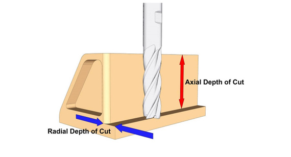
When discussing depth of cut, two distinct terms often arise: Radial Cutting Depth (RDOC) and Axial Cutting Depth (ADOC). Understanding their difference is crucial for optimizing CNC machining parts. These terms primarily apply to milling operations but have conceptual relevance in other machining processes as well.
Radial Cutting Depth (RDOC):
RDOC refers to how wide the cutter is engaging the workpiece material during a pass. In milling, this could be the horizontal distance between the tool’s cutting edge and the outer edge of the uncut region. A typical example is slot milling, where the radial depth might approach the tool’s radius or diameter, depending on the operation.
RDOC has a strong influence on cutting forces, chip thickness, and tool deflection. Excessive radial engagement can increase lateral load on the tool, potentially causing chatter or breakage.
Axial Cutting Depth (ADOC):
ADOC indicates how deep into the material the tool is cutting in a vertical or axial direction. For end milling, this is often the vertical distance from the tool’s bottom face to the top of the uncut material. In a turning operation, ADOC correlates with how much the tool reduces the workpiece diameter in one pass.
ADOC is critical for determining the volume of material removed per pass. A deeper ADOC can speed up roughing passes but may necessitate lower feed rates or spindle speeds to avoid excessive stress on the tool.
In many milling strategies, machinists must balance both RDOC and ADOC to find a sweet spot that maximizes efficiency while preserving tool life. For instance, a CNC machining factory might use a smaller axial depth for finishing passes to achieve superior surface finish, while employing a larger axial depth during roughing to quickly remove bulk material. Similarly, adjusting radial engagement can prevent tool overload or accommodate intricate geometries in custom CNC machining projects.
Both RDOC and ADOC collectively define the total volume of material removed, influencing cycle times, chip evacuation, and potential tool deflection. By understanding and optimizing these two parameters, you can tailor your CNC prototype machining and full-scale production runs to strike the perfect balance between machining speed, tool longevity, and part accuracy.
Though cutting depth may seem like a simple setting, it profoundly impacts numerous aspects of machining, from tool life to final surface quality. By carefully selecting and controlling cutting depth in machining, manufacturers can optimize throughput, reduce costs, and maintain stringent quality standards. This section explores the key reasons depth of cut is so pivotal, shedding light on how small adjustments can have large-scale effects on CNC machining parts and overall production efficiency.
Heat Generated at the Tool Tip
The depth of cut directly influences the contact area between the tool and workpiece. As this area increases, so does friction, leading to higher heat generation at the tool tip. Excessive heat can soften the cutting tool, accelerate wear, and degrade surface finishes. Controlling the cutting depth helps manage this heat, especially in materials prone to work hardening. Proper coolant application and moderate CNC machining design settings can mitigate thermal issues, ensuring stable and efficient machining processes.
Rate of Tool Wear
Tool wear is a critical cost driver in machining, affecting both tooling expenses and production downtime for tool changes. Deeper cuts subject the tool to elevated loads and can hasten wear. While shallow cuts may preserve tool longevity, they extend cycle times and potentially raise part costs. Finding the balance in cutting depth—based on the tool material, workpiece hardness, and cutting speed—enables consistent wear patterns that maximize tool service life without sacrificing production throughput.
Strength of the Machined Product
In many applications, particularly structural or load-bearing parts, the chosen depth of cut can influence residual stress distribution within the workpiece. If the cutting depth is too aggressive, it may induce excessive vibration or deflection, jeopardizing dimensional accuracy and introducing stress concentrations. Conversely, carefully graduated cuts help maintain the structural integrity of CNC machining parts, ensuring final products meet the desired mechanical properties and can withstand operational stresses.
Surface Quality
Surface finish is a hallmark of part quality, especially in industries like aerospace, automotive, and medical devices. An inadequately managed cutting depth can lead to chatter marks, tool rub, or irregular feed lines, diminishing both aesthetics and functional performance. By selecting an appropriate depth of cut, machinists can minimize these issues, achieving smoother surface finishes. This is especially pertinent for finishing passes, where shallow cuts contribute to the high-grade surface finishes demanded by custom CNC machining projects.
Controlling cutting depth is more than a matter of following manufacturer guidelines; it is a strategic choice that balances productivity and part quality. Here are some primary reasons emphasizing why controlling depth of cut is indispensable:
Precision and Accuracy:
Complex geometries or tight tolerances demand that the cutting tool removes material exactly as specified, with minimal deviation. Properly controlling depth of cut ensures each pass aligns with the CNC machining design requirements, reducing the margin for error and rework.
Cost Efficiency:
Excessive cutting depth can strain tools and machines, causing premature tool wear and risking mechanical failures. Conversely, overly shallow depth can inflate cycle times and labor costs. Striking an optimal balance leads to better resource utilization, lowering costs for the CNC machining factory.
Tool and Machine Safety:
Pushing a cutting tool beyond its depth capacity can result in catastrophic tool breakage or machine damage. Maintaining recommended depth of cut parameters ensures the machine operates within its safe limits, safeguarding both equipment and operator.
Quality Consistency:
Maintaining consistent depth of cut fosters uniformity in part quality. Whether producing hundreds or thousands of identical CNC machined parts, controlling depth of cut upholds the consistency that underpins brand reputation and reduces scrap rates.
Design Adaptability:
In custom CNC machining, different parts or sections of a single workpiece might require varied cutting depths to accommodate intricate geometries or material thicknesses. The ability to switch cutting depths seamlessly allows more complex part designs without compromising performance or costing excessive time.
Production Scheduling:
Controlling depth of cut can also help meet tight production deadlines. By adjusting depth to optimize the material removal rate, machinists can shorten production runs when needed or adopt more conservative cuts for extended tool life when project deadlines are flexible.
Overall, controlling depth of cut is about empowering CNC machining services with the agility and reliability to produce high-quality parts, manage costs, and stay competitive. Whether dealing with CNC prototype machining or large-scale output, attention to depth of cut remains a key differentiator in achieving manufacturing excellence.
Depth of cut goes beyond being a mere numeric setting in a G-code file; it influences vital elements of the machining process that can either accelerate or hinder production. Understanding these effects is essential for anyone involved in CNC machining parts manufacturing, from line operators to design engineers. This section uncovers three critical aspects: the material removal rate (MRR), cutting forces and vibrations, and chip thickness.
Material Removal Rate (MRR)
Material Removal Rate (MRR) quantifies how much material is machined away in a given timeframe, typically measured in cubic millimeters per minute (mm³/min) or cubic inches per minute (in³/min). Because MRR is a product of cutting depth, cutting speed, and feed rate, an increase in depth of cut can substantially boost MRR, thus reducing total cycle times and improving throughput.
However, while a greater depth of cut might reduce the number of passes needed, it can also introduce complications. Excessive DOC demands more power and torque from the machine, which may exceed the capacity of less robust equipment. Additionally, if the tool or spindle cannot handle the increased load, the machine might experience chatter or produce subpar surface finishes. Therefore, the ideal DOC is often determined by balancing the pursuit of a higher MRR with the practical constraints of machine power, tooling capabilities, and part geometry.
Cutting Forces and Vibrations
Increasing the depth of cut inherently raises cutting forces due to the expanded contact area between the tool and the workpiece. These elevated cutting forces can lead to vibrations or chatter, which not only degrade surface finish but also strain the machine’s spindle, bearings, and linear guides. Persistent chatter can reduce tool life, damage the workpiece, and lead to dimensional inaccuracies.
To mitigate these risks, machinists often perform a test cut or rely on established process data for CNC prototype machining. If chatter or tool deflection occurs, they may reduce the depth of cut or alter other parameters like feed rate and spindle speed. In advanced CNC machining services, sensors and monitoring systems can detect vibrations in real-time, enabling automated adjustments to maintain stable cutting conditions.
Chip Thickness and Type
Depth of cut directly influences the thickness of the chips formed during the cutting process. Thicker chips can be beneficial for heat dissipation—carrying more heat away from the cutting zone—but they also require a robust tool geometry and can increase mechanical stress. Thinner chips, conversely, may not evacuate heat as efficiently but place less strain on the cutting tool.
Chip type—ranging from continuous, segmented, or discontinuous—also ties back to cutting depth, tool geometry, and material. For instance, in steels or cast irons, deeper cuts at moderate speeds can yield segmented chips, whereas shallow cuts might produce continuous ribbons. Understanding how chip formation correlates with depth of cut allows machinists to refine process parameters for consistent chip evacuation, improved surface finishes, and stable tool temperatures.
Overall, controlling the depth of cut ensures that the CNC machining design aligns with the machine’s capabilities, the tool’s geometry, and the workpiece material’s properties. By doing so, you can optimize MRR, manage cutting forces effectively, and maintain stable chip formation—key pillars of an efficient and profitable CNC machining factory.
The concept of a “minimum depth of cut” arises when dealing with processes or parts that demand extremely fine material removal, such as finishing operations, tight-tolerance components, or fragile workpieces. While there is no universal minimum depth of cut that applies to all machining, the limit generally hinges on several factors:
Thus, the minimum depth of cut is often a project-specific value that ensures the tool can engage the material effectively, while still achieving the desired surface finish and dimensional tolerance.
For example, finishing passes might be set at 0.05 mm to 0.1 mm in certain custom CNC machining tasks. Failing to meet this threshold can result in subpar finishes, tool rubbing, or potential part damage. By understanding these constraints, machinists and engineers can tailor processes to meet stringent design requirements while preserving tool life and machine stability.
Similarly, the concept of a “maximum depth of cut” (DOC) revolves around how aggressively a machine can remove material in a single pass before encountering issues such as tool deflection, excessive heat, or machine overload. While deeper cuts improve productivity by removing more material per pass, they also raise the risk of chatter, tool breakage, and subpar surface finishes if machine or tool capabilities are exceeded. Several key factors dictate the upper bound for depth of cut:
In practice, the maximum depth of cut is discovered through a mix of tool manufacturer guidelines, shop experience, and sometimes trial-and-error. For instance, roughing passes might allow a
DOC of several millimeters in soft steels or aluminum, whereas finishing might limit the DOC to mere tenths of a millimeter. By adhering to recommended values and carefully monitoring tool and machine performance, manufacturers can expedite material removal without compromising on part quality or tool life.
The depth of cut doesn’t operate in a vacuum; it directly interacts with a variety of other machining parameters such as coolant usage, rake angle, and cutting speed. These interactions can either enhance or hinder machining performance, making it crucial for manufacturers to balance all elements cohesively. This section delves into how depth of cut synergizes with related machining parameters to shape the outcomes of CNC machining parts production.
Depth of Cut and Coolant
Coolant serves to remove heat and lubricate the cutting process. Deeper cuts produce more friction and heat, heightening the necessity for effective coolant flow. When the depth of cut is substantial, the cutting area is larger, leading to higher thermal loads on the tool. Inadequate coolant can result in excessive tool wear, thermal expansion in the workpiece, and compromised surface quality. Conversely, a well-implemented coolant strategy—featuring the correct coolant type, pressure, and application method—can mitigate temperature spikes and maintain stable cutting conditions even at more aggressive depths of cut.
Depth of Cut, Rake Angle, and Cutting Speed
The rake angle of the cutting tool influences chip flow and friction levels, making it a vital partner to depth of cut decisions. A positive rake angle can reduce cutting forces for a given DOC, facilitating deeper or faster cutting. However, too positive a rake angle may weaken the tool’s edge. Similarly, the selected cutting speed (rpm) must match the cutting depth and the tool’s rake angle characteristics. Higher speeds can lead to thinner chips and shorter cutting times but generate more heat, which can be risky if the depth of cut is also large. Coordinating depth of cut with rake angle and cutting speed is essential to strike a balance that maximizes productivity without compromising tool life or part accuracy.
Calculating the depth of cut (DOC) isn’t a one-size-fits-all procedure. Instead, it involves analyzing multiple aspects of the machining setup, from the process type (e.g., milling vs. turning) and tool geometry to the workpiece material and machine capability. Establishing the correct depth of cut ensures optimal material removal rates, tool longevity, and surface finishes. Here’s a framework that addresses the key parameters to specify before determining the DOC.
Machining Process Type (Milling, Turning, etc.):
The maximum and minimum feasible DOC vary with the type of operation. Turning typically allows for deeper cuts in a single pass compared to milling, while drilling might have unique constraints based on hole depth and diameter.
Workpiece Material:
Material properties—like hardness, ductility, and thermal conductivity—hugely influence recommended DOC. For instance, stainless steel and titanium require more conservative depths due to their toughness, whereas aluminum allows deeper cuts under the right conditions.
Tool Tip Properties:
The material, coating, geometry, and rake angle of the cutting tool define how deep it can cut without excessive wear or breakage. Manufacturer guidelines typically provide recommended DOC values.
Machine Capabilities:
Machine rigidity, available horsepower, and spindle torque limit the maximum DOC. A CNC machining factory must align these capabilities with the required DOC to avoid stalling, chatter, or structural damage.
Required Surface Finish and Tolerance:
Finer finishes or tighter tolerances may call for shallower passes. Conversely, roughing operations can push the DOC higher to expedite material removal, with finishing passes using minimal DOC for refinement.
Depth of Cut in Turning Operations
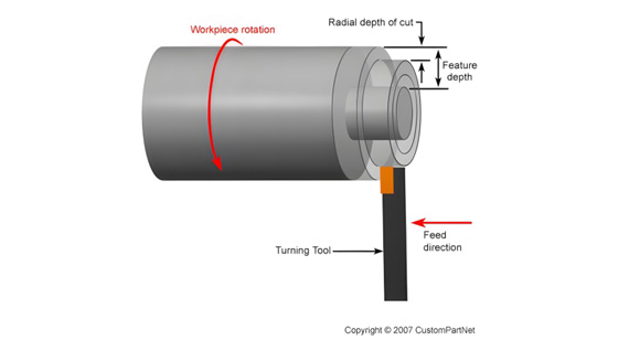
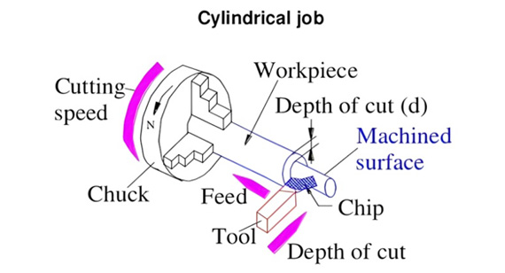
Turning operations revolve around rotating a cylindrical workpiece while the cutting tool traverses, reducing the diameter. The depth of cut here correlates directly with how much the diameter is reduced per pass. Essentially, if the lathe is set to remove 2 mm from the diameter, the radial DOC is 1 mm.
Workpiece Material
The chosen DOC depends heavily on whether the material is mild steel, cast iron, or harder alloys like Inconel. Harder materials necessitate conservative cuts, while softer metals permit more aggressive removal. The interplay between spindle rpm, feed rate, and DOC is integral to preventing surface burnishing or chatter.
Tool Tip Properties
Carbide or ceramic inserts can withstand deeper cuts at higher speeds compared to HSS tools, provided they have the right geometry (chip breakers, corner radius, etc.). The cutting insert’s recommended DOC serves as a reference point to avert excessive deflection or tool failure.
Machine Capabilities
A robust lathe with sufficient horsepower and rigidity can accommodate more substantial radial DOC. Limitations appear if the chucking force or tailstock support is insufficient for the chosen DOC, risking part slippage or poor concentricity. Monitoring vibrations is crucial, as deeper cuts elevate radial forces.
Depth of Cut in Milling
Milling operations can be more varied than turning, with different tool paths and multi-axis movements. As such, the depth of cut can be broken down into radial (RDOC) and axial (ADOC) components, each influencing distinct aspects of the milling process.
Workpiece Material
Just like in turning, metals like steel or titanium call for conservative depth-of-cut strategies to mitigate rapid tool wear, while aluminum supports deeper cuts under the same feed and speed parameters. Milling composites might limit the DOC further to prevent delamination or fiber pull-out.
Tool Tip Properties
End mill geometry—including flute count, helix angle, and corner radius—affects feasible cutting depths. A high flute count end mill might handle shallower cuts more effectively, while a single or double flute design can handle deeper plunges. Coatings such as TiAlN or AlTiN further impact how aggressively one can push the DOC.
Machine Capabilities
Factors such as spindle horsepower, torque, and the rigidity of the CNC milling machine dictate the upper limit of the depth of cut. Overstepping these capabilities invites chatter, dimensional inaccuracy, or mechanical failures like spindle overload. For CNC prototype machining, machinists might opt for moderate DOC to ensure safe operation and consistent outcomes, gradually testing more aggressive parameters once they confirm the setup’s stability.
Practical Applications
Depth of cut decisions fundamentally shape the success of various machining tasks, from roughing to finishing. For instance, an automotive cylinder head might require significant material removal in the roughing phase, calling for deeper cuts to swiftly shape the blank. The finishing phase then transitions to minimal depths to achieve a high surface finish and tight tolerances. In aerospace or medical device industries, the margin for error is slim; hence, conservative depth-of-cut strategies ensure parts remain within exacting specifications while mitigating the risk of tool wear and thermal distortion. These examples underline that practical application merges theoretical guidelines with real-world constraints, including the unpredictability of materials, machine condition, and project deadlines.
Mathematically expressing depth of cut (DOC) can clarify the relationship between the final and initial dimensions of the workpiece, guiding consistent and repeatable results. The exact formula may vary slightly based on the operation, but the underlying principle remains consistent across turning, milling, and other CNC machining services. A well-defined formula helps machinists anticipate the necessary passes, estimate production times, and ensure parts remain within tolerance.
Calculated by:

In turning, for example, if d_w is the workpiece’s initial diameter and d_m is the machined diameter after one pass, half the difference between these two measures is the radial DOC. This approach accounts for the fact that turning reduces the workpiece’s radius, effectively cutting into both sides of the diameter.
What Does dw Represent?
d_w symbolizes the initial dimension—commonly the diameter or thickness—of the workpiece prior to the machining pass. For turning, it’s the original outer diameter; for milling, it might be the initial surface height. Monitoring d_w ensures you have an accurate baseline for calculating how much material is removed.
What Does dm Represent?
d_m is the final dimension—again, diameter or thickness—after the machining operation. Measuring d_m confirms how much the workpiece has been reduced, indicating the actual DOC achieved. In custom CNC machining, verifying d_m is essential to ensure the part meets the desired specifications, especially when dealing with high-value materials or complex geometry.
Turn
When turning, the formula for depth of cut is often the radial engagement. A deeper pass might reduce the diameter significantly, but the finishing pass typically employs a shallower depth to refine the surface. This approach ensures both speed in bulk removal and precision in final dimension control.
Milling
In milling, especially face or end milling, a similar principle applies but is often split between axial and radial directions. The formula remains relevant, with dw and dm representing the initial and final surface heights or widths. Milling operations might also factor in stepdown approaches, where each pass reduces the surface by a portion of the total DOC to maintain stable cutting conditions.
Although the fundamental concept of depth of cut applies across various machining methods, each process carries unique requirements, limitations, and best practices. This section summarizes how depth of cut typically differs among turning, milling, drilling, grinding, broaching, sawing, planing, shaping, and even EDM. By appreciating these differences, you can tailor depth-of-cut decisions to each specific operation in your CNC machining factory.
CNC Turning
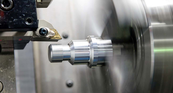
Turning is well-suited for deeper cuts during roughing, given a rigid setup and sufficient spindle horsepower. Depths of a few millimeters per pass are common in simpler steels. For finishing, depths might drop below 0.5 mm to achieve desired surface finishes and tight dimensional tolerances.
CNC Milling
In milling, the radial and axial depths of cut must both be managed. Slot milling or pocket milling might involve lighter radial depths to avoid tool breakage, while face milling could support heavier axial depths. High-speed milling techniques, where shallow cuts pair with high feed rates, are an alternative approach for certain materials.
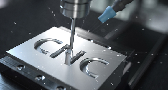
CNC Drilling
Drilling’s depth of cut equates to hole depth, which can be limited by drill geometry, flute length, and chip evacuation concerns. Exceeding recommended depths can result in drill breakage or overheating. Common practice includes peck drilling cycles for deep holes, breaking the total depth into increments to clear chips and reduce heat.
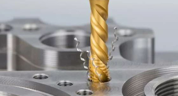
Grinding
Depth of cut in grinding is minimal, often in the thousandths of a millimeter range, to achieve high precision and superior surface finish. Larger depths can induce burning or residual stress, undermining part quality. Therefore, multiple shallow passes are the norm, especially for precision or hardened components.
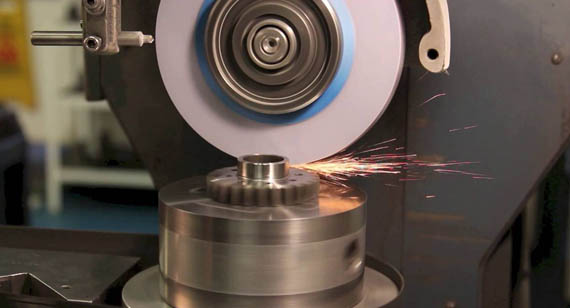
Broaching
Broaching involves a toothed tool that progressively removes material with each tooth. The depth of cut increments from tooth to tooth, culminating in the final profile. Each tooth’s depth is fixed by the broach design, so machinists have limited flexibility. However, the process can produce complex shapes, like splines or keyways, with excellent repeatability.
Sawing
In sawing operations, depth of cut depends on the blade’s geometry and the workpiece thickness. The process focuses on straight cuts rather than intricate geometries. While deeper cuts might expedite cutting, they risk blade deflection or overheating, especially if the material is dense or thick.
Planing and Shaping
Both planing and shaping involve a single-point cutting tool traversing across or along a workpiece. Depth of cut is often shallow, especially in finishing passes, as these processes aim for flat, precise surfaces. The machine’s stroke length and power constraints limit how aggressively the tool can be set.
Electrical Discharge Machining (EDM)
Although not a conventional subtractive cutting method, EDM also deals with a form of “depth of cut.” In EDM, material removal relies on electrical discharges, making deeper cavities more time-consuming and prone to issues like poor flushing of dielectric fluid. Machinists optimize DOC in EDM to balance removal rate with surface integrity and dimensional accuracy.

Depth of cut doesn’t exist in isolation—it interplays with coolant use, tool geometry, rake angle, and cutting speed. Each factor influences or is influenced by depth of cut, demanding a holistic approach to CNC machining part design. By coordinating these elements, you can elevate productivity, manage tool wear, and achieve top-quality finishes. Let’s dissect the primary relationships among depth of cut, coolant, rake angle, and cutting speed.
Coolant and Depth of Cut
Coolant lowers cutting temperatures and flushes chips away, mitigating the heat generated by deeper cuts. Without adequate coolant, deeper cuts may lead to rapid tool degradation or localized thermal expansion in the workpiece. The correct coolant—be it oil-based, water-soluble, or synthetic—further stabilizes the cutting zone, supporting higher DOC without risking tool breakage.
Rake Angle Interaction
The rake angle heavily dictates how a cutting tool engages the workpiece material, affecting chip formation and friction levels. A positive rake angle can make deeper cuts feasible by reducing cutting forces. Conversely, a negative rake angle might limit the depth of cut because it elevates chip resistance and tool stress. Finding synergy between rake angle and DOC prevents mechanical overload or chatter, critical for achieving stable machining conditions.
Cutting Speed and Its Correlation
Cutting speed determines how fast the tool interacts with the material. Lower speeds can tolerate deeper cuts without causing undue heat, but also lengthen production times. Higher speeds produce thinner chips, but might exacerbate heat generation if the cut is too deep. Machinists often adjust cutting speed alongside depth of cut to optimize MRR and control thermal stress on both the tool and the workpiece.
Defining an optimal depth of cut is a balancing act that must consider multiple facets of the machining ecosystem. From CNC machining design constraints to the mechanical properties of tools and materials, each factor either expands or restricts the feasible range of DOC. Knowing how these elements interconnect empowers machinists and engineers to fine-tune processes for cost, efficiency, and part quality.
Material Hardness
Harder materials like tool steels or Inconel demand smaller depths of cut to avoid exacerbating cutting forces and damaging the tool. Softer metals such as aluminum and brass can sustain more aggressive DOC while remaining stable, provided the machine can handle the higher load.
Tool Materials and Geometry
The composition of cutting tools, whether high-speed steel, carbide, or ceramics, dictates permissible DOC ranges. Geometry factors like flute number, helix angle, corner radius, and rake angle also shape how deep the tool can plunge without chatter or breakage.
Machine Power and Stability
A robust machine with ample horsepower and a rigid frame can maintain stable cutting at greater depths. Limited horsepower or less stable setups, conversely, risk chatter, dimensional inaccuracy, and tool wear when the DOC is pushed too high.
Cutting Speeds and Feed Rates
Cutting parameters must harmonize with the chosen DOC. Deeper cuts typically necessitate lower speeds or feeds to manage heat and stress, whereas shallower cuts allow faster speeds and higher feed rates. Balancing these settings is essential for consistent part quality and cost-effective production.
Required Surface Finish
Finer finishes often require shallower depths of cut to ensure minimal tool marks and better dimensional fidelity. While a deeper cut can expedite bulk removal, a subsequent finishing pass with a more moderate DOC may be employed to meet tight surface roughness requirements.
Coolant Use and Type
The decision to use flood coolant, mist, or dry machining influences maximum feasible DOC. Adequate coolant flow can handle deeper cuts by dispersing heat and flushing away chips, but inadequate coolant severely limits cutting depth to avoid thermal issues.
Determining the correct depth of cut involves aligning practical experience, manufacturer data, and the specific requirements of each job. By considering factors like material properties, tool geometry, machine capacity, and finishing criteria, machinists can systematically arrive at an optimal DOC for any operation. Below are guidelines to help orchestrate this process effectively in custom CNC machining or CNC prototype machining environments.
Start with Manufacturer Recommendations
Cutting tool manufacturers often provide recommended DOC ranges for different materials and tool types. These serve as a reliable baseline, ensuring novices or even seasoned operators have a safe starting point.
Consider Material Properties
Evaluate hardness, ductility, and potential for work hardening. For instance, stainless steel might require less aggressive depths than aluminum. Adjust the baseline accordingly.
Monitor Tool Wear
If tool edges degrade too fast, the chosen DOC might be too high. Conversely, if productivity is low with minimal tool wear, you might safely increase the DOC for higher throughput.
Use Test Cuts
Conduct short trial passes to fine-tune the chosen DOC. Observing chip formation, surface finish, and machine load helps confirm if the parameters are optimal or need tweaking.
Adjust Surface Finish Requirements
For finishing passes demanding sub-micron finishes, reduce the DOC to minimize cutter marks and thermal stress, ensuring dimension accuracy and visual appeal.
Check Machine Capabilities
Consult spindle load meters or performance logs to confirm the machine can handle the load without approaching power or rigidity limits.
By integrating these steps, you can systematically calibrate depth-of-cut parameters for each job, balancing the trade-offs between productivity, cost, and quality. A disciplined approach ultimately yields stable, consistent, and efficient machining results—hallmarks of a professional CNC machining factory.
Optimizing depth of cut is more than a means to reduce cycle time or protect the tool—it’s about integrating all machining variables into one cohesive strategy that boosts overall productivity. A well-chosen DOC can significantly elevate CNC machining parts output, enhance quality, and extend cutting tool longevity. This section examines how depth of cut adjustments can transform a machining process by maximizing material removal while safeguarding the tool and part integrity.
Increase Machining Efficiency with Optimal Depth of Cut
Setting an optimized DOC can remove substantial amounts of material per pass, streamlining roughing operations. In many cases, adopting deeper cuts early in the process shortens total cycle time, enabling a swift transition to finishing passes. This approach is especially beneficial for custom CNC machining projects where short lead times are a competitive advantage.
Reduce Tool Wear and Extend Tool Life
Tools subjected to excessive DOC face higher loads, friction, and heat, accelerating wear or even precipitating sudden failure. By carefully balancing DOC with feed rate and cutting speed, machinists can keep tool stress within safe limits. The result is more uniform wear patterns, fewer tool replacements, and minimized downtime for tool changes—yielding a more continuous and cost-effective operation.
Impact on Surface Finish and Dimensional Accuracy
Finishing cuts often necessitate shallow depths to produce fine surface finishes and adhere to close tolerances. Conversely, deeper cuts can sometimes induce surface irregularities or dimension drift. By maintaining a strategic DOC throughout roughing and finishing stages, you can refine the part’s final profile to meet precision demands. This synergy ensures the part’s form and surface quality both align with project specifications.
To Determine the Most Effective Depth of Cut for Any Given Project, Several Factors Need to Be Considered:
Balancing these considerations helps you refine depth-of-cut decisions that underpin an efficient and reliable CNC machining services operation.
Despite best efforts, challenges often arise when specifying the depth of cut in machining operations. Variations in material properties, tool deflection, heat management, and other factors can complicate or undermine the process. Recognizing these hurdles and applying proven solutions preserves productivity and maintains CNC machining part design fidelity. Below are the most frequent issues faced by machinists and practical measures to address them.
Inconsistent Material Properties
Different batches of the same metal or alloy can exhibit variations in hardness, yield strength, or impurity levels. These differences can derail optimal DOC settings established for earlier runs. The solution often lies in test cuts and real-time monitoring, adjusting parameters if cutting forces or spindle loads deviate from normal. Maintaining thorough material traceability and adopting flexible feed and speed strategies also help manage these inconsistencies.
Tool Deflection and Breakage
An overambitious DOC can induce high radial or axial forces, leading to tool deflection or outright breakage. Tool deflection manifests as dimensional inaccuracies and poor surface finishes. Solutions include reducing the DOC, using more rigid toolholders, increasing tool diameter, or opting for advanced tool materials like carbide or ceramic. Deploying fixtures that enhance part rigidity further mitigates deflection concerns.
Heat Buildup
Deeper cuts escalate friction and, consequently, heat generation. Without effective coolant or lubrication, this heat can accelerate tool wear or cause thermal expansion in the part, jeopardizing dimensional accuracy. Implementing high-pressure coolant systems, using thermally stable cutting fluids, or employing intermittent “peck” strategies in drilling can disperse heat more effectively, sustaining stable machining conditions.
Surface Finish Quality
A mismatch between an aggressive DOC and finishing requirements can produce visible tool marks, chatter, or rough surface textures. The fix usually entails dividing machining operations into roughing and finishing passes. Machinists can adopt smaller finishing cuts, slower feeds, or advanced tool geometries for improved surface finishes, ensuring that final pass meets the stringent demands of custom CNC machining for high-end products.
High Power Consumption
Excessively deep cuts not only strain the tool but also draw high power from the CNC machine’s spindle. This can lead to increased operational costs and potential overloading of the machine motor. Monitoring power consumption helps identify when a DOC is too ambitious. Adjusting cutting parameters or investing in higher-horsepower machinery often solves this problem, making it feasible to proceed with deeper cuts if necessary.
Chip Evacuation Difficulties
Thick or volumetric chips can clog tool flutes or obscure the cutting zone, elevating the risk of chip re-cutting and tool breakage. The introduction of specialized chip breakers, angled flutes, or improved coolant nozzles can enhance chip evacuation. Sometimes, adopting segmented passes or step-down strategies ensures that chips are sufficiently small to be managed easily.
Machining challenging materials—such as heat-resistant superalloys, hardened tool steels, or high-temperature composites—demands a meticulous approach to cutting depth in machining. The mechanical properties of these materials can intensify tool wear, accentuate heat buildup, and exacerbate the potential for part distortion. Below are strategies to address these challenges.
Reduce Speeds and Increase Feeds:
Hard or exotic alloys often necessitate lower cutting speeds to avoid thermal damage to the tool. Increasing feed rates slightly can still maintain productivity while controlling heat more effectively.
Use Specialized Cutting Tools:
Opt for carbide or ceramic inserts designed for high-temperature wear resistance. The geometry of these tools typically supports smaller depths of cut, ensuring gradual material removal that mitigates wear.
Optimize Cutting Fluids:
High-performance coolants with strong lubricity help counter the friction and temperatures generated by tough materials. Cryogenic cooling methods are sometimes employed for extremely demanding alloys.
Control Depth of Cut:
Shallow or moderate DOC prevents excessive forces on the tool, helping maintain stable cutting performance. Progressive or multi-pass strategies yield better results than a single heavy pass.
Combining these approaches forms a holistic plan for manufacturing automotive or aerospace CNC machined parts from challenging materials without compromising on quality or efficiency.
It’s easy to conflate “depth of cut” with “chip thickness,” but the two concepts refer to different dimensions in the machining process. Depth of cut measures how far the tool penetrates into the workpiece in a single pass, while chip thickness pertains to the thickness of the metal layer that becomes the chip. Although they interrelate, especially in CNC machining design, each has unique implications for cutting performance, tool wear, and finished part quality.
Understanding this distinction helps machinists fine-tune both the cutting depth in machining and the feed rate to regulate chip load. Excessively thick chips can cause tool overload or short tool life, whereas thin chips may hamper heat dissipation and slow production cycles. Striking the right balance ensures efficient, stable cutting in CNC machining services.
Comparing Chip Thickness Values to Depth of Cut Values
While depth of cut focuses on the unmachined to machined surface distance, chip thickness is highly influenced by the feed rate and the cutting edge geometry. This section lays out how these two parameters differ in conceptual terms but converge practically to shape the success of CNC machining parts.
Cutting Process
During the cutting process, depth of cut defines the total amount of material to be removed in a pass. Meanwhile, feed per revolution or per tooth determines chip thickness, i.e., how large each chip is as it exits the tool’s cutting edge.
Chip Removal Process
A deeper cut typically correlates with a greater chip cross-sectional area, but the feed rate modifies chip thickness. Lower feeds produce thinner chips but more friction-based heat, whereas higher feeds yield thicker chips with improved heat evacuation—assuming the tool and setup can handle the mechanical load.
Cutting Ratio vs. Chip Compression Ratio
The cutting ratio measures how much the original workpiece thickness changes as it transforms into chip thickness. Meanwhile, chip compression ratio reflects how the chip’s geometry is condensed relative to its original thickness, influenced by friction and rake angle. Neither metric directly equals the depth of cut, although deeper cuts often alter compression dynamics by raising cutting forces.
Depth of Cut vs. Cutting Force and Power
A large depth of cut inevitably elevates cutting forces, requiring more spindle power and torque. The correlation implies that as DOC grows, so must the machine’s capacity to handle it. This becomes clear in heavy roughing operations where cycle times are reduced at the expense of higher power draw.
Chip Velocity vs. Cutting Speed
Chip velocity—the speed at which the chip is sheared off and moves along the rake face—differs from cutting speed, which is the relative speed between tool and workpiece. Depth of cut indirectly influences chip velocity by changing how the cutting tool engages material. Although controlling chip velocity is more nuanced, the main focus in day-to-day CNC machining services remains on depth of cut and cutting speed for consistent production outcomes.
Determining the optimal depth of cut demands a holistic evaluation of machine capabilities, tool geometry, material properties, and production objectives. Below are essential pointers to guide machinists, engineers, and CNC machining factory managers in establishing depth-of-cut parameters that foster productivity and preserve part quality.
Material Properties
Properties like hardness, toughness, and thermal conductivity strongly shape feasible DOC ranges. For instance, high-carbon steel or heat-treated alloys may demand incremental passes with conservative depth, whereas aluminum or mild steel could sustain deeper engagements. Understanding your material’s machinability rating is foundational for balancing productivity and tool longevity.
Types of Machine Operations
Each machining process (turning, milling, drilling, etc.) features distinct constraints on how deep the cutting tool can engage. Milling might require balancing radial and axial engagements, while turning largely focuses on radial DOC for diameter reduction. Drilling and boring have unique depth-of-hole limitations and chip evacuation challenges.
Machine Tool Capabilities
A machine’s torque, horsepower, and structural rigidity determine its capacity to handle deeper cuts. Overstepping these capabilities risks mechanical wear, chatter, or subpar part accuracy. Reviewing manufacturer guidelines and monitoring real-time power loads helps match the chosen DOC to machine performance potential.
Cutting Tool Features
Tool geometry (e.g., flute design, rake angle, corner radius) and material composition (carbide, HSS, ceramic) influence feasible DOC. High-performance inserts or coated tools permit greater depth for roughing operations, whereas uncoated or worn tools require more conservative settings to avoid breakage.
When it comes to CNC prototype machining, custom CNC machining, or large-scale production, VMT stands out as a reliable collaborator. Our advanced equipment, seasoned engineers, and comprehensive approach to process optimization ensure every detail—like cutting depth—is refined to perfection. By partnering with VMT, you gain access to a team committed to delivering top-tier CNC machining parts, upholding stringent tolerances, and providing full support from initial design to final inspection.

Depth of cut is more than a straightforward numeric entry in a CAM program; it shapes the entire machining process, from tool life to surface quality and from heat generation to dimensional fidelity. Whether you’re roughing out large volumes of material in a high-speed milling operation or performing finishing passes on delicate, high-precision components, choosing the correct DOC is paramount. By balancing the factors—machine capabilities, tool geometry, material characteristics, and desired finish—manufacturers can realize efficient, cost-effective, and high-quality outcomes. The synergy between precise depth of cut management and other key variables like feed rate, spindle speed, and coolant usage exemplifies best practices in modern CNC machining services. As you refine your CNC machining part design and production strategies, keep the role of depth of cut at the forefront, ensuring every pass moves you closer to manufacturing excellence.
What Is the Depth of Cut?
Depth of cut refers to the distance between the uncut material surface and the machined surface after a single pass of the cutting tool. It determines how much material is removed in one go, influencing cutting forces, tool wear, and surface finish.
How to Find the Depth of the Cut?
You can measure the depth of cut by subtracting the post-machining dimension from the original dimension of the workpiece, often dividing by two for turning operations. Alternatively, referencing tool manufacturer data or machine settings helps determine recommended DOC values.
What Is the Depth of Cut for CNC Machines?
The depth of cut for CNC machines varies depending on the machining process (milling, turning, drilling, etc.), the workpiece material, and the machine’s power and rigidity. It’s typically set based on manufacturer guidelines, tool geometry, and project-specific considerations like surface finish and tolerance requirements.
What Is the Depth of Cut for Drill Presses?
In drilling operations, depth of cut corresponds to hole depth. It is limited by the drill bit length, flute design, and chip evacuation strategies such as peck drilling. Exceeding recommended depths can cause tool breakage, poor surface finish, and inaccurate holes.
What Is the Rule for Depth of Cut?
The general rule is to choose a depth of cut that balances material removal efficiency with tool life and surface quality. This often involves incremental passes for roughing and lighter cuts for finishing, guided by cutting tool and machine capability recommendations.
What Is the 4-Inch Rule in Drilling?
The “4-inch rule” in drilling suggests that beyond a certain hole depth (around 4 inches, depending on material), additional techniques like peck drilling, specialized coolant delivery, or advanced drill geometries are required to manage chip removal and heat buildup efficiently.
What Is the Maximum Depth of Drilling?
Maximum drilling depth is constrained by the drill bit’s geometry, machine horsepower, and chip evacuation efficiency. For deep holes, peck cycles or gun drilling methods may be used to maintain stable chip clearance and adequate coolant flow.
What Is the Minimum Depth of Turning?
In turning, the minimum depth of cut depends on tool tip radius and the required surface finish. If the depth is too shallow—less than the cutting edge radius—there’s a risk of rubbing instead of cutting, leading to poor surface quality and tool damage.
What Is the Rule for Depth of Drilling?
The depth of drilling is commonly determined by the drill’s flute length, the workpiece thickness, and the required final hole depth. For deeper holes, repeated pecking or specialized tooling ensures chip evacuation and mitigates heat or tool breakage.
What Is the Depth of Cut for End Mills?
For end mills, depth of cut (axial DOC) varies with the tool diameter, length-to-diameter ratio, and material hardness. Many CNC machinists start at around 0.5 to 1.0 times the tool diameter for roughing passes, adjusting as needed based on chip evacuation and machine response.
What Is the Depth of Cut for Cut-Off Saws?
In cut-off or slitting saw operations, the depth of cut equals the workpiece thickness. Achievable depth depends on the saw blade diameter, tooth configuration, and feed rates. Exceeding recommended depths can cause binding, blade deflection, or poor surface finish.
What Is the Recommended Depth of Cut for Slotting Operations?
Slotting typically demands a modest depth of cut to ensure proper chip evacuation and maintain stable cutting forces. Machinists often apply 0.5 to 1.0 times the cutter diameter as an initial guideline, adjusting based on part rigidity and material constraints.
What Does Depth of Cut Depend On?
Depth of cut depends on a blend of factors: the machining process (milling, turning, etc.), tool geometry, material properties, machine capacity, desired surface finish, and tolerance requirements. Striking a balance among these variables ensures efficient material removal without sacrificing tool life or part integrity.
