16 years one-stop China custom CNC machining parts factory

Hey there I’m VMT Sam!
With 25 years of CNC machining experience we are committed to helping clients overcome 10000 complex part-processing challenges all to contribute to a better life through intelligent manufacturing. Contact us now
 371 |
Published by VMT at Dec 10 2021
371 |
Published by VMT at Dec 10 2021


Geometrical dimensions and tolerances (GD&T) refers to the geometric shapes of precision CNC machined parts, which are interlocked and point to the shape, direction, position, contour and tolerance (as defined in Table 4). For operations in the United States, the American Society of Mechanical Engineering (ASME) applies the ASMEY14.5 standard as the authoritative guide for the geometric tolerances of precision CNC machining parts. It uses symbols and rules for standardized dimensional communication.
The "Y14" name of the standard determines the governance as the Engineering Drawing and Related Document Convention Standards Committee, while the "5" designation determines the size and tolerance subcommittee. ASMEY14.5 standard symbols describe different geometric characteristics in technical drawings and are used as a tool for precise tolerance communication between engineers and manufacturers of precision CNC machined parts.
The vector template library "Dimensions and Tolerances" contains 45 geometric dimension and mechanical tolerance symbols, geometric symbols, annotations, text boxes and inserts.
Use these geometric dimensions and tolerance (GD&T) shapes to create mechanical drawings with additional annotations.
Geometric Dimensioning and Tolerance of Precision CNC Machining Parts (GD&T) is a system for defining and transferring engineering tolerances. Precision CNC machining parts use a symbolic language on engineering drawings and computer-generated three-dimensional solid models to clearly describe the nominal geometry and its allowable changes.
It tells manufacturing personnel and machines how much precision and precision each controlled feature of precision CNC machining parts needs. GD&T is used to define the nominal (theoretically perfect) geometry of parts and components, define the allowable variation and possible size of each feature, and define the allowable difference between each feature.

The shape example "Design Elements-Dimensions and Tolerances" was created using Concept Draw Pro graphical and vector drawing software and mechanical engineering solutions extension of the concept Dlaw Solutions Park.
According to the role of the elements in the body, there are the following names.
Ideal and actual elements of precision CNC machining parts:
(1) Ideal elements are absolutely correct elements with geometric meaning, such as points, straight lines, planes, spheres, etc. It does not have any shape error and is in an ideal state.
(2) The actual elements are the elements formed by machining that actually exist on the precision CNC machined parts. It is usually replaced by measured elements. Due to the existence of CNC machining and measurement errors, the actual shapes and positions of points, lines, and surfaces cannot have ideal shapes and positions.
Measured elements and benchmark elements of precision CNC machined parts:
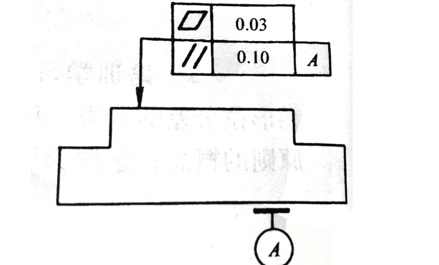
(1) The measured element is the element that gives the shape and position tolerance on the drawing. It is the object of detection: the surface pointed by the leader arrow in the figure below.
(2) The reference element is the element used to determine the direction and position of the measured element and should be marked with the reference symbol: plane A is the reference element as shown in the figure below.
Single elements and related elements:
(1) A single element is an element that only requires the shape tolerance of the element itself. Elements with only shape tolerance requirements and no position tolerance requirements on the drawings of precision CNC machining parts belong to a single element.
(2) Relevant elements are elements that have a functional relationship between the measured element and other elements. The elements required for position tolerances on the drawings of precision CNC machined parts are related elements. Functional relationship refers to the azimuth relationship between elements, such as vertical, parallel, coaxial, symmetrical, etc.

 +86 15099911516


 Read more