16 years one-stop China custom CNC machining parts factory

Hey there I’m VMT Sam!
With 25 years of CNC machining experience we are committed to helping clients overcome 10000 complex part-processing challenges all to contribute to a better life through intelligent manufacturing. Contact us now
 63 |
Published by VMT at Aug 19 2026 | Reading Time:About 4 minutes
63 |
Published by VMT at Aug 19 2026 | Reading Time:About 4 minutes


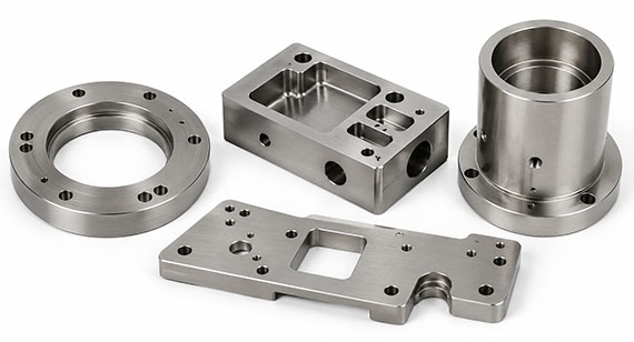
Common metal like aluminum, stainless steel, or carbon steel can't be that highly dimensional precision across fluctuating thermal environments like invar 36( also named 4J36,UNS K93600, W.Nr. 1.3912, FeNi36, Nilo 36 ). This 4J36 invar alloy' ability (resistance to volumetric expansion or contraction over a wide thermal window) make it stand out among aerospace, optics, metrology, and scientific instrumentation fields. However, machining invar 36 can be difficulty for its low thermal conductivity and good ductile property, and there are details about wall thickness, coating thickness, flatness, etc to be considered.
This blog will take you to fully get invar 36 properties, uses, machining challenges and solution; and surface treatments, cost, and design tips of invar 36 parts production. At the end, we will also share a case study of how we manufactured ultra-stable optical mounting seats with invar 36 ( a mounting datum flatness of 0.003 mm and hole position tolerances within +/- 0.005 mm) for our clients.
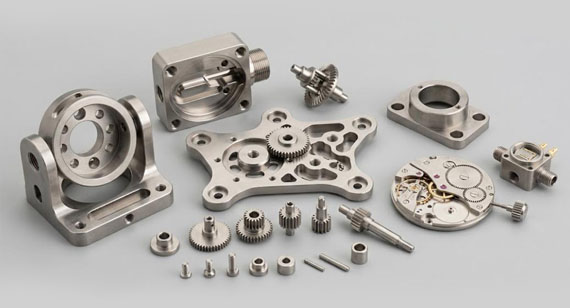
For the invar 36, “36 ” means its composition of 36% nickel (balance iron) while “invar ” comes from “invariable” ( keeping almost-unchanged dimensional stability when the temperature changes).
To be more specifically, this “invariable” is its biggest advantage:
Invar 36 parts have thermal expansion rate of 1.6×10⁻⁶/℃ across the temperature changes of -80℃~230℃.
This almost means the lowest coefficient of thermal expansion among all common metals and alloys, which is roughly 1/10 of that of carbon steel.
Therefore, when you products are highly sensitive to temperature changes, especially like the precision optical or lab instruments, precision laser equipment, precision clocks, precision aerospace sensors or remotes, precision watches, the invar 36 can be the definitely top choice.
Key Properties of 4J36 (Invar Alloy 36)
Besides from its most noteworthy thermal expansion rate of 1.6×10⁻⁶/℃ ( under temp of -80℃~230℃), invar alloy 36 also has the following core physical and mechanical properties for engineering calculation or machining effects:
| Property | Value | Tips |
| Density | 8.10 g/cm³ | None |
| Curie Point | 230°C – 279°C | (Ferromagnetic below the Curie point and non-magnetic paramagnetic above it) You may consider whether precision instruments require protection against magnetic interference. |
| Thermal Expansion (CTE) | 1.6 × 10⁻⁶ / °C (-80°C to 230°C) | Biggest advantage. |
| Thermal Conductivity | 10 W/(m·K) | The very low conductivity causes heat to concentrate on cutting tools rather than dissipating via chips, and this may cause tool wear and tolerance buildup during precision CNC machining. |
| Tensile Strength | ~ 590 MPa | Delivers moderate load-bearing capability enough for precision mechanical frameworks. |
| Yield Strength | ~ 410 MPa | High ductility and yield behavior cause gummy cutting action and built-up edge (BUE) on CNC cutting tools, similar to austenitic stainless steel. |
| Hardness | ~ 141 HBS (Annealed) | Soft in the annealed state, making it prone to material tearing if tool edges are not sharp. |
| Heat Treatment & Hardening | Non-heat-treatable; Work-hardenable via cold working | Cannot be hardened by heat treatment (e.g., quenching); can only be strengthened through cold working, though final strength and hardness remain moderate. |
| Machinability Rating | ~ 60% (relative to AISI B1112 = 100%) | Slightly more difficult to machine than 316 austenitic stainless steel due to severe work hardening, sticky chips, and trapped thermal friction. |
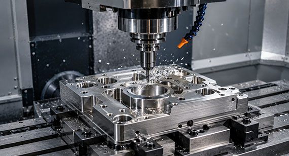
When the low thermal expansion coefficient (the components must maintain dimensional stability under temperature variations) is a must, then you should use the invar 36 rather than other alloys. Here are a few the invar component examples:
1. Precision Optics & Laser Systems
Temperature fluctuations can alter optical alignments by fractions of a micron, compromising beam delivery or image resolution. Invar 36 is widely used to build ultra-stable structural frameworks for optical systems:
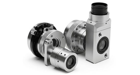
2. Aerospace & Satellite Components
Invar 36 prevents structural warpage and drift in critical flight hardware:
3. Scientific Instruments
High-precision instrumentation relies on material stability to ensure repeatable data and long-term calibration:
4. Other Precision Manufacturing
Beyond optics and space flight, Invar 36 provides solution-oriented stability for some other specialized mechanical assemblies:
When You May Use Other Metals for Parts? (Considering Performance and Cost)
1. Production Cost of Invar 36 Machined Parts Can be Higher than Other Metal Alloys
While Invar 36 excels in thermal stability, it is not always the practical choice for every engineering application. Due to its high nickel content (~ 36% ) and specialized production process, Invar 36 raw material is substantially more expensive than common carbon steel, aluminum, and many stainless steel grades. Additionally, its difficult CNC machinability (higher tool wear and slower processing times compared to 316 stainless steel) further increases total manufacturing costs.
2. Thus, you may evaluate the trade-offs between performance and cost when selecting alternative engineering metals:
CNC machining is fundamentally a subtractive manufacturing process. To produce a finished component, a CNC machine uses cutting tools to systematically remove material from a solid block of raw Invar 36 until the target geometry is achieved.
Machining invar 36 is hard primarily because:
Thus, if a shop approaches Invar 36 like “the relatively easy-to-machine” carbon steel or aluminum, the material will quickly damage cutting tools, warp under internal stress, or produce out-of-tolerance parts.
How a Professional Factory Machines the Invar 36 ( vs. The Risks of Incorrect Techniques )
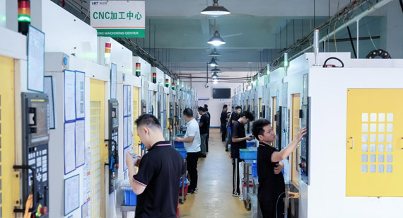
To maintain tight tolerances and pristine surface finishes without damage much cutting tools ( tool fees is a portion of you production cost as well), a professional CNC machining factory usually deal with invar 36 with the following practice:
| Machining Factor | How the Factory Do? | Consequence of Incorrect Technique |
| Cutting Speed (Vc) | Lowered cutting speeds (35–65 m/min for milling/turning) to control friction and thermal accumulation. | Running at high speeds causes intense heat to concentrate on the cutter. This leads to rapid tool wear, edge failure, and dimensional drift across the part. |
| Tool Material & Geometry | Micrograin carbide tools with positive rake angles (10°–15°), sharp cutting edges, and thin PVD coatings (TiAlN/AlTiN). | Dull or heavily honed edges push material rather than shear it, work-hardening the surface layer and causing tool chipping. |
| Feed Rate & Cutting Engagement | Constant positive feed to keep the tool edge cutting below any work-hardened surface layer. | Dwell time or feeds that are too light cause the tool to slide over hardened material, causing blade failure and surface tearing. |
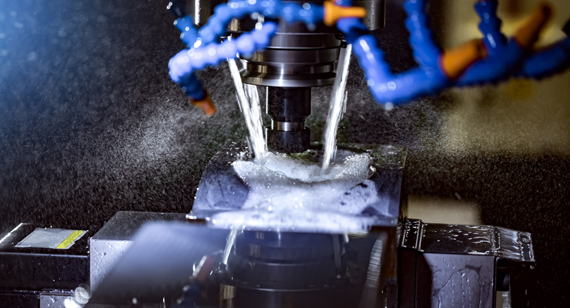
| Coolant Application | High-Pressure Coolant (HPC) directed directly at the cutting edge and chip interface. | Without high-pressure fluid, gummy chips weld onto the insert edge, leading to rough surface roughness and bad tolerances. |
| Threading Strategy | Thread milling or carbide forming taps instead of standard cut tapping. | Standard taps bind on continuous, gummy stringer chips, leading to broken taps lodged inside deep blind holes. |
| Stress Relief Process | Multi-stage machining (Rough → Stress Relief Anneal at ~310°C–350°C → Finish). | Uncareful material removal releases internal stress, causing thin-walled or long components to warp after release from the fixture. |
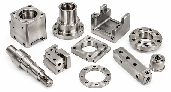
To ensure exceptional dimensional stability, avoid machining distortion, and optimize manufacturing yield, you can consider the following Design for Manufacturability (DFM) recommendations when designing Invar 36 (4J36) prototype parts:
Proper Structural Dimensioning and Mounting Design Tips
Proper structural dimensioning and mounting design are essential when designing Invar 36 (4J36) precision components to avoid machining deformation and ensure long-term dimensional stability.
| Design | Tips | Notes |
| Wall Thickness | Recommended minimum wall thickness of 1.5 mm (can be relaxed to 1.0 mm for non-load-bearing pockets with multi-stage annealing). | Prevents wall chatter, tool deflection, and elastic deformation during CNC milling. |
| Corner Radius | Internal pocket bottom/side radii set to R = 0.25 × pocket depth (and not less than R1.5 mm). | Allows the use of stiffer end mills, reducing tool deflection and localized heat accumulation. |
| Aspect Ratio (Length Ratio) | Keep unsupported wall height-to-thickness ratio under 8:1. | Prevents thin-wall chatter caused by cutting forces and post-machining spring-back distortion. |
| Mounting | Use flexures, 3-point kinematic mounts, or slotted holes with shoulder screws; integrate stainless steel inserts or nitrided steel thread inserts for critical threads. | Absorbs differential thermal expansion of dissimilar metals, prevents over-constraint deformation, and avoids thread galling in the soft Invar matrix. |
| Threading Requirements | Avoid blind threads smaller than M3; design tap drill holes for 65%–70% thread engagement. | To retain over 95% of full thread strength. |
| Flatness Target | Standard as-machined flatness is usually 0.05 mm / 100 mm; achievable down to 0.002–0.005 mm with precision grinding or lapping. | Noting the process limits for optical bases and precision mounting datums. |
Surface Finishes for Invar 36 and the Coating Thickness
The table below outlines the dimensional impact and visual appearance for common finishing processes:
| Surface Treatment Process | Thickness / Dimensional Change (Pre-reserve for Fitment) | Invar 36 Prototype Visual Appearance |
| Vibratory Tumbling | Micron-level removal (~ -1 to -3 µm) | Delivers a uniform, non-directional satin/semi-bright metallic finish. |
| Media Blasting | Surface roughness alteration (dimension change < 2 µm) | Creates a uniform matte gritty or satin silk texture. |
| Powder Coating | 60 – 120 µm (thick) | Forms a heavy, highly wear-resistant colored or textured paint coat (e.g., matte black, textured gloss), fully obscuring the raw metal color. |
| Polishing, or Fine Grinding | Micro-removal (-0.5 to -5 µm) | Produces a mirror-like metal finish. |
| Electroless Nickel Plating (ENP) | 5 – 15 µm (Per side buildup) | Delivers a bright or semi-bright silver-white metallic luster (with a subtle warm nickel tint), enhancing corrosion resistance and surface hardness. |
| Phosphate Coating (Phosphating) | < 2 µm (Ultra-thin) | Forms a dark gray to black matte conversion film; primarily used for baseline rust prevention, oil retention, and light anti-reflection. |
| Laser Marking | None | Creates a black or gray permanent mark directly on the metal surface for part numbers, QR codes, or brand names. |
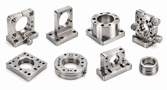
Delivering Ultra-Stable Optical Mounting Seats with Invar 36
A leading manufacturer of high-precision laser instruments reached out to us. The client required a batch of ultra-precision optical mounting seats to align sensitive lens elements, and they said that minor ambient temperature fluctuations caused subtle dimensional shifts in components, leading to micro-optic misalignment and beam distortion. Unsure of which material to choose, the client emphasized that they prioritized component quality, strict thermal stability, and long-term performance over cost.
Solution
To address this challenge, our engineering team recommended Invar 36 (4J36)—a 36% nickel-iron alloy with a near-zero Coefficient of Thermal Expansion of 1.6 × 10⁻⁶/°C between -80°C and 230°C.
To process this ductile and thermally insulating alloy without post-machining distortion, our factory implemented a specialized multi-stage manufacturing protocol.
Components underwent rough CNC milling followed by a controlled thermal stress relief annealing cycle at 330°C for 2 hours before final semi-finishing and finishing. Utilizing high-precision multi-axis CNC machines, sharp micrograin carbide tooling, and high-pressure coolant, we achieved a mounting datum flatness of 0.003 mm and hole position tolerances within +/- 0.005 mm.
For surface aesthetics and functional performance, optical mounting datums were precision-lapped to an ultra-fine surface roughness of Ra 0.4 µm, while external non-functional surfaces received glass bead blasting (#120 mesh) to create an elegant satin silk finish that conceals tool marks and prevents stray light reflections inside the laser housing.
Results
Prior to shipment, 100% of the parts underwent full dimensional and surface inspection on our CMM equipment. Upon receipt, the client installed the Invar 36 seats into their test bed and subjected them to rigorous thermal cycling tests from -20°C to 80°C, where beam drift remained virtually undetectable. Delighted with the flawless mounting accuracy, pristine surface finish, and exceptional thermal stability, the client praised the performance of the components and willing to keep a long-term partnership with our factory.
When sub-micron dimensional stability under fluctuating temperatures for your products is the priority, Invar 36 (4J36) remains the suitable one for optics, aerospace, metrology, and scientific instrumentation. While its near-zero coefficient of thermal expansion solves critical thermal drift challenges, successfully bringing Invar 36 components from blueprint to production requires navigating work-hardening, localized thermal trapping, and post-machining residual stress. But partnering with an experienced precision machining supplier ensures these issues are expertly managed.
Looking for ultra-stable, high-reliability parts tailored to your exact application requirements, or or advice on optimizing your Invar 36 prototype design? Welcome to contact us to gain free DFM review and quick quote with 24 hours! [2D Drawings (PDF files), 3D Drawings (IGS/STP/STEP files)].
Send your 2D drawings, 3D CAD models, material requirements, critical tolerances, flatness requirements, surface-finish requirements, prototype quantity and production quantity. VMT will review manufacturability, machining strategy, inspection and quotation requirements.
All information and uploaded files are secure and confidential.
1 Tell us what you need
2 Get solution & quote
3 Approve production
Email: inquiry@vimetal.com.cn
What type of alloy is Invar 36?
It is a single-phase austenitic nickel-iron precision alloy containing 36% nickel and ~64% iron.
Can Invar 36 be hardened by heat treatment?
No. Invar 36 cannot be hardened through heat treatment processes like quenching or aging. It can only be work-hardened through cold working.
Is Invar 36 hard to machine?
Yes. Invar 36 is classified as a difficult-to-machine alloy due to its high ductility, strong work-hardening behavior, gumminess, and low thermal conductivity (10 W/m·K).
What is the material equivalent of Invar 36?
Invar 36 is equivalent to :
Does Invar 36 rust, and how can it be protected against corrosion?
Yes. Although Invar 36 contains approximately 36% nickel, it contains virtually no chromium, making it susceptible to atmospheric oxidation and rusting in humid environments. To prevent corrosion, components are commonly treated with Electroless Nickel Plating (ENP) at a uniform thickness of 5 to 15 µm, or a thin phosphate conversion coating for basic indoor protection.
What is the difference between Invar 36 and Super Invar?
While Invar 36 contains 36% nickel and ~64% iron with a CTE of approximately 1.6 × 10⁻⁶/°C (-80°C to 230°C), Super Invar incorporates roughly 5% cobalt (32% Ni, 5% Co, ~63% Fe) to achieve an even lower CTE of near-zero (approx. 0.35 × 10⁻⁶/°C at ambient temperatures). However, Super Invar is more expensive, slightly more prone to phase transformation at cryogenic temperatures, and even more challenging to machine than Invar 36.
The technical information and manufacturing advice shared on the VMT website are for general guidance only. While we strive for accuracy, VMT does not guarantee that the processes, tolerances, or material properties mentioned are applicable to every specific project. Any reliance you place on such information is strictly at your own risk. It is the buyer's responsibility to provide definitive engineering specifications for any production orders. Final specifications and service terms shall be subject to the formal contract or quotation confirmed by both parties.


 +86 15099911516




 Read more