16 years one-stop China custom CNC machining parts factory

Hey there I’m VMT Sam!
With 25 years of CNC machining experience we are committed to helping clients overcome 10000 complex part-processing challenges all to contribute to a better life through intelligent manufacturing. Contact us now
 932 |
Published by VMT at Dec 13 2021
932 |
Published by VMT at Dec 13 2021


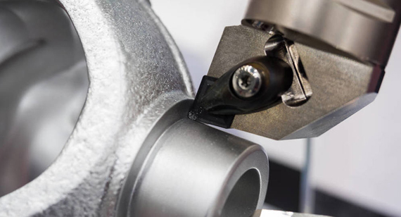
1. The geometry of the cutting part of the milling cutter in the turning and milling combined processing
(1) Rake face: The surface through which the chips flow on the tool is called the rake face.
(2) Backward surface: The surface opposite to the surface produced during cutting on the CNC machined part is called the flank surface.
(3) Secondary flank: The flank of the secondary cutting edge is formed when the cutting tool intersects with the rake surface.
(4) Main cutting edge: starting from the point of zero entering angle on the cutting edge, and at least one cutting edge is used to cut out the entire cutting edge of the transition surface on the CNC machined part.
(5) Minor cutting edge: The cutting edge other than the main cutting edge also starts at the point where the entering angle is zero, but it extends in the direction away from the main cutting edge.
(6) Tool tip: refers to a relatively small part of the cutting edge at the connection between the main cutting edge and the secondary cutting edge.
2. The geometric angle of the milling cutter for turning and milling compound processing
To correctly determine and measure the geometric angle of the milling cutter, two coordinate planes of the angle measurement datum are required, namely the base plane and the cutting plane. The main geometric angle of the CNC machining milling cutter is the clamp between each cutter face or cutting edge and the coordinate plane. Horn. The base plane is a plane passing through a selected point on the cutting edge.
It is parallel or perpendicular to a plane or axis suitable for installation or positioning of the tool during manufacturing, sharpening and measurement, and its orientation is perpendicular to the assumed main movement direction. The base surface on the milling cutter is generally a plane containing the milling cutter axis.
The cutting plane is a plane that is tangent to the cutting edge and perpendicular to the base plane through a selected point on the cutting edge. The cutting plane on the milling cutter is generally a plane tangent to the outer cylinder (cone) of the CNC milling cutter. The main cutting plane on the main cutting edge and the secondary cutting plane on the secondary cutting edge. The main geometric angles of the milling cutter are as follows:
(1) Rake angle: The rake angle is the angle between the front surface and the base surface, measured in an orthogonal plane perpendicular to the base surface and the cutting plane.
(2) Relief angle: The relief angle is the angle between the back surface and the cutting plane, measured in an orthogonal plane.
(3) Edge angle and helix angle: The edge angle of the face milling cutter and the helix angle of the cylindrical milling cutter are the included angle between the main cutting edge and the base surface, measured in the main cutting plane.
(4) Main deflection angle: The main deflection angle is the angle between the main cutting plane and the assumed working plane parallel to the feed direction, measured in the base plane.
(5) Secondary deflection angle: The secondary deflection angle is the angle between the secondary cutting plane and the assumed working plane, measured in the base plane.

 +86 15099911516


 Read more