16 years one-stop China custom CNC machining parts factory

Hey there I’m VMT Sam!
With 25 years of CNC machining experience we are committed to helping clients overcome 10000 complex part-processing challenges all to contribute to a better life through intelligent manufacturing. Contact us now
 342 |
Published by VMT at Nov 22 2022
342 |
Published by VMT at Nov 22 2022


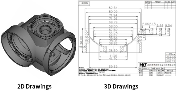
The design drawing of CNC machining parts is one of the main bases for product processing in an enterprise. The design drawing of parts has a very important relationship with the precision and quality of CNC machining products. Therefore, when designing the part drawing, it is also necessary to comply with some technical requirements according to the performance and characteristics of the product. In this article, VMT will introduce the technical requirements of general part drawings in detail.
1). Heat Treatment Requirements
1. Carburizing depth 0.3mm.
2. Carry out high temperature aging treatment.
3. After quenching and tempering, HRC50~55.
4. High frequency quenching for CNC parts, tempering at 350~370℃, HRC40~45.
1. The casting tolerance zone is symmetrical to the basic dimension configuration of the rough casting.
2. The unmarked shape tolerance shall meet the requirements of GB1184-80.
3. The allowable deviation of the unmarked length dimension is ±0.5mm.

3). General Technical Requirements
1. Remove burrs.
2. CNC machining parts to remove scale.
3. There should be no scratches, scratches and other defects that damage the surface of the parts on the surface of CNC parts.
4). CNC Machining and Assembly Requirements
1. When assembling, the taper pin and the hole should be painted and inspected, and the contact rate should not be less than 60% of the matching length, and should be evenly distributed.
2. The flat key and the two sides of the keyway on the shaft should be in even contact, and there should be no gap between the mating surfaces.
3. The number of tooth surfaces in contact with the spline assembly at the same time shall not be less than 2/3, and the contact ratio shall not be less than 50% in the direction of the length and height of the spline teeth.
4. After the flat keys (or splines) of the sliding fit are assembled, the relative parts can move freely without uneven tightness.
5. After bonding, remove excess adhesive that flows out.
6. The outer ring of the bearing and the semi-circular hole of the open bearing seat and bearing cover must not be stuck.
7. The outer ring of the bearing should be in good contact with the semi-circular hole of the open bearing seat and the bearing cover. When inspecting with coloring, it should be 120° symmetrical to the center line with the bearing seat and 90° symmetrical to the center line with the bearing cover. even contact. When checking with a feeler gauge within the above range, the 0.03mm feeler gauge shall not be inserted into 1/3 of the outer ring width.
8. After the bearing outer ring is assembled, it should be in even contact with the end face of the bearing cap at the positioning end.
9. After the rolling bearing is installed, it should be flexible and stable to rotate by hand.
10. The joint surfaces of the upper and lower bearing shells should be closely attached and cannot be checked with a 0.05mm feeler gauge.
11. When fixing the bearing bush with the locating pin, drill the hinge and match the pin under the condition that the mouth and end face of the bush are flush with the opening and closing face and end face of the relevant bearing hole. After the pin is driven in, it must not be loosened.
12. The bearing body and the bearing seat of the spherical bearing should be in uniform contact, and the contact should not be less than 70%.
13. When the surface of the alloy bearing lining is yellow, it is not allowed to use, and there is no nucleation phenomenon within the specified contact angle. The nucleation area outside the contact angle shall not be greater than 10% of the total area of ??the non-contact area.
14. The datum end face of the gear (worm gear) and the shaft shoulder (or the end face of the positioning sleeve) should fit together, and check with a 0.05mm feeler gauge. And the verticality requirements of the gear reference end face and the axis should be guaranteed.
15. The joint surface of the gear box and the cover should be in good contact.
16. Strictly check and remove the sharp corners, burrs and foreign objects left in the processing of parts before assembly. Make sure that the seals are not scratched when they are installed.
17. Each seal must be saturated with oil before assembly.
18. The assembly of rolling bearings is allowed to be heated by oil, and the temperature of the oil should not exceed 100 °C.
19. After the gear is assembled, the contact spots and backlash of the tooth surface should meet the requirements of GB10095 and GB11365.
20. Sealing packing or sealant is permitted when assembling hydraulic systems, but should be prevented from entering the system.
21. Parts and components (including outsourced parts and outsourced parts) that enter the assembly must have a certificate from the inspection department before they can be assembled.
22. CNC machined parts must be cleaned and cleaned before assembly, and there should be no burrs, flashes, oxide scales, rust, chips, oil, colorants and dust.
23. Before assembly, the main fit dimensions of parts and components, especially the interference fit dimensions and related accuracy, should be reviewed.
24. The parts are not allowed to be knocked, bumped, scratched and corroded during the assembly process.
25. When tightening screws, bolts and nuts, it is strictly forbidden to strike or use unsuitable bits and wrenches. 10. Fasteners with the specified tightening torque must be tightened with a torque wrench and tightened according to the specified tightening torque.
26. When the same part is fastened with multiple screws (bolts), each screw (bolt) should be tightened crosswise, symmetrically, gradually and evenly.
5). Edges and Corners of CNC Machining Parts
1. Sharp corners/sharp corners/sharp edges are blunt.
2. The corner radius R5 is not specified.
3. The unmarked chamfer is 2×45°.
6). Coating Requirements
1. The time interval between the surface to be coated by shot peening or manual rust removal and the priming shall not be more than 6h.
2. The surfaces of the riveted parts in contact with each other must be coated with anti-rust paint with a thickness of 30-40 μm before connecting. Lap edges should be closed with paint, putty or adhesive. Primer damaged due to processing or welding, to be repainted.
3. Before painting the surface of all steel parts to be painted, rust, scale, grease, dust, mud, salt and dirt must be removed.
4. Before rust removal, use organic solvent, lye, emulsifier, steam, etc. to remove grease and dirt on the surface of steel parts.
7). Piping Requirements
1. When assembling, tighten the pipe clamps, supports, flanges and joints that are fixed with threaded connections to prevent loosening.
2. The welded part of the prefabricated pipe shall be subjected to a pressure test.
3. When the piping is replaced or transported, the separation port of the piping must be blocked with tape or plastic pipe to prevent any debris from entering, and a label must be attached.
4. All pipes should be free of end flash, burrs and chamfers prior to assembly. Use compressed air or other methods to remove debris and rust attached to the inner wall of the pipe.
5. Before assembly, all steel pipes (including prefabricated pipes) should be degreased, pickled, neutralized, washed with water and anti-rust.
8). Repair Welding Requirements

1. Welding should be performed in a horizontal position as far as possible.
2. During repair welding, the electrode should not swing too much laterally.
3. When surfacing welding on the surface of steel castings, the overlap between the weld bead shall not be less than 1/3 of the width of the weld bead. The welding meat is full, and the welding surface is free of burns, cracks and obvious nodules. The appearance of the welding seam is beautiful, and there are no defects such as bite, slag, pores, cracks, and splashes; the welding wave is uniform.
4. The defects must be completely removed before welding, the groove surface should be smooth and smooth, and there should be no sharp corners.
5. According to the defects of steel castings, the defects in the welding area can be removed by shovel excavation, grinding, carbon arc gouging, gas cutting or mechanical processing.
6. Dirt such as sticky sand, oil, water, rust and other dirt within 20mm around the welding area and the groove must be thoroughly cleaned.
7. During the whole welding process, the temperature of the preheating zone of the steel casting shall not be lower than 350°C.
9). Casting Requirements

1. The molding sand, core sand, core bone, succulent, sticky sand, etc. on the casting should be smoothed and cleaned.
2. Correction of wrong type and cast deviation of boss should be done to achieve a smooth transition and ensure the appearance quality.
3. For the wrinkles on the non-machined surface of the casting, the depth is less than 2mm, and the spacing should be greater than 100mm.
4. The non-machined surfaces of machine product castings shall be shot peened or roller treated to meet the requirements of cleanliness Sa2 1/2.
5. Castings must be water toughened.
6. The surface of the casting should be flat, and the gate, burr, sticky sand, etc. should be cleaned.
7. Castings are not allowed to have casting defects such as cold partitions, cracks and holes that are detrimental to the use.
8. Cold space, cracks, shrinkage cavities, penetrating defects and serious incomplete defects (such as under-casting, mechanical damage, etc.) are not allowed on the casting surface.
9. The castings should be cleaned without burrs or burrs. The pouring risers on the non-processed surface should be cleaned and flush with the surface of the castings.
10. The cast characters and signs on the non-machined surface of the castings should be clearly identifiable, and the positions and fonts should meet the requirements of the drawings.
11. The roughness of the non-machined surface of the casting, sand casting R, is not more than 50μm.
12. Castings should be free of pouring risers, flying spurs, etc. The residual amount of the pouring riser on the non-machined surface should be leveled and polished to meet the surface quality requirements.
13. The molding sand, core sand and core bone should be removed from the casting.
14. The casting has inclined parts, and its dimensional tolerance zone should be symmetrically arranged along the inclined plane.
10). Requirements for CNC Machining Parts
1. Rolling and finishing the surface, there should be no peeling after rolling.
2. There should be no oxide scale on the surface of the parts after the final heat treatment. Finished mating surfaces and tooth surfaces should not be annealed.
3. The surface of the CNC machined thread is not allowed to have defects such as black skin, bumps, random buckles and burrs.
4. CNC machined parts should be inspected and accepted according to the procedure, and only after passing the inspection of the previous procedure can they be transferred to the next procedure.
5. The parts after CNC machining are not allowed to have burrs.
6. The finished parts should not be placed directly on the ground, and necessary support and protection measures should be taken. The machined surface is not allowed to have rust, bumps, scratches and other defects that affect performance, life or appearance.
11). Forging Requirements

1. Forgings are not allowed to have visible cracks, folds and other appearance defects that affect the use. Local defects can be removed, but the cleaning depth should not exceed 75% of the machining allowance. Defects on the non-machined surface of the forging should be cleaned up and smoothly transitioned.
2. Forgings are not allowed to have white spots, internal cracks and residual shrinkage cavities.
3. The nozzles and risers of the ingots should have enough cutting amount to ensure that the forgings have no shrinkage holes and serious deflection.
4. The forgings should be forged on a forging press with sufficient capacity to ensure that the interior of the forgings is fully forged.
The above are the 11 technical requirements on the drawings of precision CNC machining parts, have you learned it?

 +86 15099911516


 Read more