15 years one-stop China custom CNC machining parts factory

Hey there I’m VMT Sam!
With 25 years of CNC machining experience we are committed to helping clients overcome 10000 complex part-processing challenges all to contribute to a better life through intelligent manufacturing. Contact us now
 713 |
Published by VMT at Oct 27 2024 | Reading Time:About 2 minutes
Geometric Dimensioning and Tolerancing (GD&T) is an essential framework used in engineering to define and communicate the allowable variations in the shape and position of a part. Among its many features, straightness plays a pivotal role in ensuring that components fit together correctly and function as intended. Understanding straightness within the context of GD&T, including its definitions, measurement techniques, and applications, is crucial for manufacturers and engineers alike. This guide aims to provide a comprehensive overview of straightness in GD&T, offering insights into its measurement methods and practical implications in CNC machining.
Straightness is a geometric tolerance that defines the condition of a line or surface being perfectly straight within specified limits. In GD&T, straightness is often applied to both the centerline of cylindrical parts and the surface of flat components. This tolerance ensures that the part maintains its intended functionality by preventing misalignment or undue stress during operation. For example, in a machined shaft, straightness ensures that the shaft will rotate smoothly without wobbling or excessive wear on bearings. By controlling straightness, engineers can enhance the performance, longevity, and overall quality of machined parts.

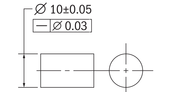
In GD&T, straightness is represented by specific symbols and dimensions that clarify the requirements for a particular feature. The straightness symbol consists of a straight line with two arrows pointing to the feature that is being controlled. This symbol is usually accompanied by a tolerance value that indicates the allowable deviation from the ideal straightness. The application of straightness can be indicated for various features, including surfaces, edges, and centerlines. For example, a straightness tolerance of 0.1 mm means that the feature must not deviate from a true straight line by more than 0.1 mm over its entire length.
Surface straightness refers specifically to the flatness of a surface along its length, ensuring that it remains within specified tolerances. This concept is crucial in applications where surfaces must interface correctly with other components. In GD&T, surface straightness is a critical factor in determining how parts align and function together, influencing the assembly process and the performance of the final product.
How to Measure Surface Straightness?
Measuring surface straightness requires precision instruments to ensure accuracy. The two most common tools used are micrometers and Coordinate Measuring Machines (CMM).
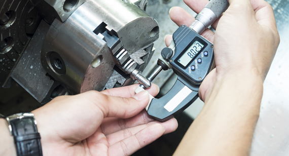
Micrometer
A micrometer is a manual tool that allows for precise measurement of small distances. To measure surface straightness, a micrometer can be used along different points of the surface. By taking multiple readings along the length of the surface and calculating the differences, the degree of straightness can be determined. This method, while accurate, can be time-consuming and requires a skilled operator to interpret the results correctly.

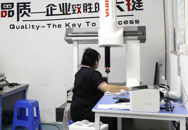
Coordinate Measuring Machine (CMM)
A CMM is a sophisticated machine used for measuring the physical geometrical characteristics of an object. It can be operated manually or controlled via computer. When measuring surface straightness, the CMM probes the surface at various points, collecting data that is processed to analyze the straightness condition. This method is highly accurate and can significantly reduce measurement time, making it a preferred choice in modern manufacturing environments.

The straightness of a derived centerline refers to maintaining a straight line through the center of a cylindrical feature, such as a hole or a shaft. This concept is critical in applications where the alignment of components is vital for their functionality. In GD&T, the derived centerline is crucial for controlling the orientation and positioning of various features.
MMC/LMC Dimensions
Maximum Material Condition (MMC) and Least Material Condition (LMC) are two concepts that are often applied to the straightness of derived centerlines. MMC refers to the condition where a feature contains the maximum amount of material (e.g., the largest diameter of a hole), while LMC refers to the condition with the least amount of material (e.g., the smallest diameter of a hole). The relationship between these conditions and straightness tolerances helps engineers define the acceptable limits for manufacturing.
Bonus Tolerance
Bonus tolerance is an additional allowance given when a feature is produced at its MMC. For example, if a hole is manufactured at its MMC, the straightness tolerance may be relaxed, allowing for greater deviation. This concept provides manufacturers with flexibility in production, accommodating variations that can occur during machining while still ensuring the overall quality of the parts.
Measuring the straightness of a derived centerline requires specialized techniques to ensure accuracy. One common method involves using a CMM to probe the centerline at multiple points, allowing for precise calculations of any deviations. Another method utilizes laser systems to project a straight line along the centerline, which can then be compared against the actual feature to assess straightness. Both methods are effective in providing detailed information about the alignment of cylindrical features and ensuring they meet the specified tolerances.
While straightness and flatness are both geometric tolerances used in GD&T, they serve different purposes and apply to different features.
Line vs. Plane
Straightness pertains to a line, such as the centerline of a cylindrical feature, whereas flatness concerns a plane, such as a surface of a part. Essentially, straightness measures the degree to which a line can deviate from being perfectly straight, while flatness measures the degree to which a surface can deviate from being perfectly flat.
2D vs. 3D
Straightness is often considered a 2D characteristic since it applies to the line in a two-dimensional space, while flatness is a 3D characteristic, assessing the surface across three dimensions. This distinction is vital in determining which tolerance to apply based on the geometric features being manufactured.
Control Features
Control features also differ between straightness and flatness. Straightness is generally used to control features that are meant to be aligned, such as the axis of a shaft, while flatness is used to control surfaces that must be uniformly flat for proper mating with other components. Understanding these differences is crucial for engineers and machinists in the design and manufacturing process.
Straightness in GD&T is a fundamental aspect of quality assurance in CNC machining and manufacturing. By understanding the principles of straightness, including its definitions, measurement techniques, and applications, engineers can effectively design parts that meet stringent performance standards. As manufacturers strive for precision and reliability, mastering the concept of straightness will enhance overall product quality and functionality. Working with experienced partners like VMT can help ensure your engineering projects achieve their desired outcomes.
What is Straightness and Flatness?
Straightness refers to the condition of a line, while flatness refers to the condition of a surface.
What is Straightness Error?
Straightness error is the deviation of a line from being perfectly straight within specified limits.
What is flatness in GD&T?
Flatness is a tolerance that controls how much a surface can deviate from being flat.
What is straightness in GD&T?
Straightness is a geometric tolerance that specifies how straight a line or surface must be.
What standard is used for the straightness symbol?
The straightness symbol is defined by the ASME Y14.5 standard for GD&T.
Does straightness require a datum?
Straightness does not always require a datum but may reference one for certain applications.
Can straightness be used to control a surface?
Yes, straightness can control the surface when specified for the centerline of a surface feature.
How to check straightness?
Straightness can be checked using tools like micrometers, CMMs, or laser systems.
Ready To Start Your Next Project?
Get Instant Quote

Request a Free Quote
Send us a message if you have any questions or request a quote. We will get back to you ASAP!
