15 years one-stop China custom CNC machining parts factory
 2307 |
Published by VMT at Jan 16 2025
Have you ever faced a situation where a weld fails, causing a critical component to malfunction? It’s a frustrating and costly problem that can disrupt production and compromise the quality of your products. Imagine pouring time and resources into manufacturing CNC machining parts, only to have defects undermine your efforts, leading to wasted materials and missed deadlines. Understanding welding defects is essential to prevent these issues and ensure the integrity of your custom CNC machining projects. This comprehensive guide explores 19 common welding defect types, their causes, and effective solutions to help you maintain high standards in your CNC machining factory and services.
Welding defects can significantly impact the quality and durability of CNC machining parts. By identifying and addressing these defects early, you can enhance the reliability of your products and reduce production costs. Whether you’re involved in CNC prototype machining or large-scale manufacturing, this guide provides valuable insights into the most prevalent welding defects and how to resolve them effectively.
Ready to dive into the world of welding defects and learn how to overcome common challenges in your CNC machining processes? Let’s explore the various types of welding defects, their causes, and practical solutions to ensure flawless welds every time.
Preface
Welding is a fundamental process in the manufacturing of CNC machining parts, playing a crucial role in assembling components with precision and strength. However, despite its importance, welding is not without its challenges. Welding defects can arise from various factors, including material issues, improper techniques, and environmental conditions. These defects can compromise the structural integrity and functionality of the final product, leading to increased costs and reduced reliability. Understanding the different types of welding defects, their causes, and how to address them is essential for anyone involved in CNC machining services, whether in a CNC machining factory or providing custom CNC machining solutions. This guide aims to provide a clear and detailed overview of the 19 most common welding defect types, offering practical solutions to help you achieve high-quality welds consistently.
A welding defect is any imperfection or flaw that occurs during the welding process, affecting the quality and performance of the welded joint. These defects can range from minor surface irregularities to significant internal flaws that compromise the strength and integrity of the weld. Welding defects are undesirable because they can lead to product failure, safety hazards, and increased maintenance costs. In the context of CNC machining parts, welding defects can undermine the precision and durability that are critical to the functionality of the final product.
Welding defects can be categorized into external and internal types. External defects are visible on the surface of the weld, such as cracks, porosity, and slag inclusions. Internal defects, on the other hand, are hidden within the weld and require specialized inspection techniques to detect. Understanding the nature of these defects and their underlying causes is crucial for implementing effective solutions and improving overall welding quality. By addressing welding defects promptly and effectively, manufacturers can ensure that their CNC machining parts meet the highest standards of performance and reliability.
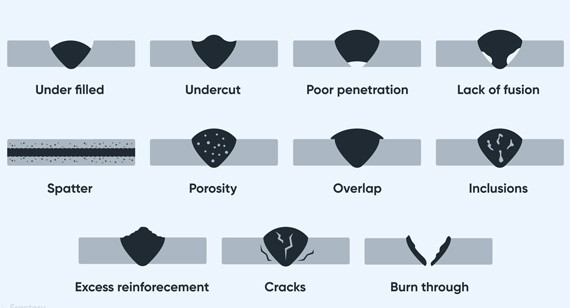
Welding defects can be broadly classified into external and internal defects, each with its own set of characteristics and implications for the quality of the weld. External defects are visible on the surface of the weld and can often be detected through visual inspection. Internal defects are hidden beneath the surface and require more sophisticated inspection methods, such as ultrasonic testing or radiographic analysis, to identify. Understanding the distinction between these two categories is essential for diagnosing issues and implementing appropriate corrective measures in CNC machining services.
External Welding Defects
External welding defects are imperfections that occur on the surface of the weld, making them easily identifiable through visual inspection. These defects can affect both the aesthetic appearance and the functional integrity of the weld. Common external welding defects include cracks, porosity, slag inclusions, undercut, and spatter. Each of these defects has specific causes and requires targeted solutions to ensure a high-quality weld.
Internal Welding Defects
Internal welding defects are hidden imperfections that occur within the weld or the base metal, making them more challenging to detect. These defects can significantly impact the strength and reliability of the weld, even if the surface appears flawless. Common internal welding defects include lack of fusion, incomplete penetration, internal porosity, and internal cracks. Detecting these defects typically requires non-destructive testing (NDT) methods, which are essential for ensuring the integrity of critical CNC machining parts.
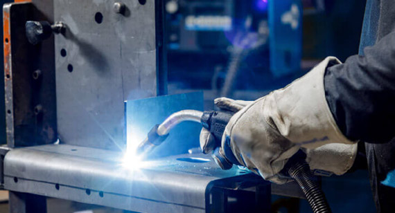
Welding defects can be divided into three main categories: dimensional defects, discontinuities, and defects in material properties. Each category encompasses various types of defects that can occur during the welding process, affecting the quality and performance of the weld. Understanding these categories helps in diagnosing issues and applying appropriate solutions to enhance the reliability of CNC machining parts.
Dimensional Defects
Dimensional defects involve deviations from the intended dimensions of the weld or the components being joined. These defects can result from improper welding techniques, incorrect settings on welding equipment, or issues with the alignment of the parts. Common dimensional defects include warping, distortion, and incorrect weld bead size. Ensuring precise control over the welding process and proper alignment of parts are crucial for preventing dimensional defects in CNC machining services.
1. In the Weld
Dimensional defects in the weld refer to inconsistencies in the shape, size, or position of the weld bead. These defects can compromise the mechanical properties of the weld, leading to weakened joints that may fail under stress. Common issues include uneven weld bead profiles, excessive bead size, or insufficient weld material. Proper welding techniques, precise control of welding parameters, and regular inspection can help prevent dimensional defects in the weld area.
2. In the Play
Dimensional defects in the play involve gaps or misalignments between the parts being welded. These gaps can lead to weak joints that are more susceptible to failure. Causes include poor alignment of the parts, improper fixturing, or excessive welding speed. Ensuring accurate alignment and using appropriate fixturing methods are essential for minimizing gaps and maintaining the integrity of the welded joint.
Discontinuities
Discontinuities are irregularities or flaws within the weld or the base metal that disrupt the continuity of the material. These defects can significantly reduce the strength and reliability of the weld, making it prone to failure. Discontinuities are further classified into internal and external types, each requiring specific detection and remediation techniques.
Defects in Material Properties
Defects in material properties refer to changes or inconsistencies in the physical or chemical characteristics of the welded material. These defects can result from improper welding techniques, unsuitable materials, or unfavorable environmental conditions during welding. Common issues include variations in hardness, brittleness, or ductility of the weld area compared to the base metal. Maintaining proper welding parameters and selecting appropriate materials are crucial for preventing defects in material properties, ensuring that the weld meets the required performance standards for CNC machining parts.
Classification of Discontinuities
Weld discontinuities are flaws that interrupt the continuity of the weld or the base material, potentially weakening the joint and leading to failure. These discontinuities are categorized based on their location and nature, including internal and external types, as well as volume and plane discontinuities. Understanding the different classifications of weld discontinuities is essential for identifying and addressing these defects effectively.
Discontinuities in welding are imperfections that disrupt the uniformity and integrity of the welded joint. They can occur in various forms and locations, each posing different challenges for detection and repair. Proper identification and classification of these discontinuities are critical for maintaining the quality and strength of CNC machining parts. By understanding the nature of weld discontinuities, manufacturers can implement targeted solutions to prevent and mitigate these defects.
Internal Discontinuities
Internal discontinuities are flaws that occur beneath the surface of the weld or within the base metal. These defects are not visible through normal inspection methods and require specialized techniques to detect. Common internal discontinuities include porosity, slag inclusions, lack of fusion, and internal cracks. These defects can significantly weaken the weld, making it susceptible to failure under load or stress. Non-destructive testing (NDT) methods, such as ultrasonic testing or radiographic inspection, are essential for identifying internal discontinuities and ensuring the integrity of the weld.
External Discontinuities
External discontinuities are visible flaws that occur on the surface of the weld. These defects can be easily identified through visual inspection and can range from minor surface imperfections to significant structural flaws. Common external discontinuities include surface cracks, spatter, undercut, and overlap. While some external discontinuities may only affect the appearance of the weld, others can compromise its strength and functionality. Proper welding techniques, careful control of welding parameters, and thorough inspection are necessary to prevent and address external discontinuities in CNC machining parts.
Volume Discontinuities
Volume discontinuities are defects that occur within the body of the weld or the base metal, disrupting the internal structure and continuity of the material. These defects can include porosity, slag inclusions, and internal cracks, which weaken the weld and reduce its load-bearing capacity. Volume discontinuities are typically caused by issues such as inadequate shielding gas, contamination of the weld area, or improper welding techniques. Preventing volume discontinuities requires strict control over welding conditions, proper material preparation, and the use of appropriate welding parameters.
Plane Discontinuities
Plane discontinuities are defects that occur along a plane or boundary within the weld or the base metal, disrupting the continuity of the material along that plane. These defects can include cracks, separations, and misalignments, which compromise the integrity of the weld and increase the risk of failure. Plane discontinuities are often caused by thermal stresses, improper cooling rates, or residual stresses from the welding process. Addressing plane discontinuities involves optimizing welding parameters, ensuring proper cooling rates, and using techniques such as preheating and post-weld heat treatment to minimize residual stresses.
Welding defects can vary widely in their nature and impact, affecting the quality and performance of the welded joint. Among the numerous types of discontinuities associated with the welding process, 19 are particularly common and noteworthy. Understanding these defects, their causes, and how to address them is essential for maintaining high standards in CNC machining services and ensuring the reliability of your CNC machining parts.
1. Weld Cracks
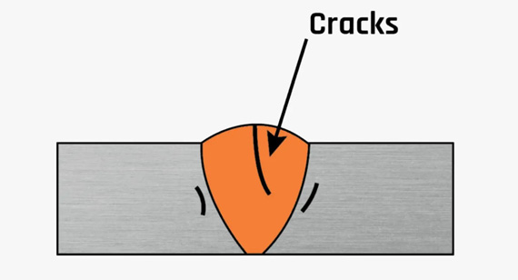
Weld cracks are fractures that occur within the weld or the heat-affected zone (HAZ) of the base metal. These cracks can significantly weaken the joint, making it prone to failure under stress or load. Weld cracks can be classified based on the temperature at which they form: hot cracks and cold cracks.
Depending on the Temperature at Which the Cracks Appear, Cracks May Appear As:
Causes of Weld Cracks
Weld cracks can result from various factors, including:
Preventing Weld Cracks
To prevent weld cracks, consider the following solutions:
2. Craters
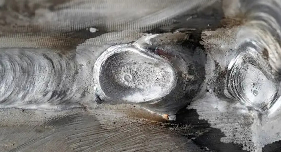
Craters are shallow depressions that form at the end of a weld bead, typically occurring at the termination point of a weld pass. These defects result from improper welding techniques, such as insufficient filler material or excessive heat input during the weld termination.
Causes of Craters
Craters are primarily caused by:
Preventing Craters
To prevent craters, implement the following measures:
3. Lack of Penetration or Incomplete Penetration
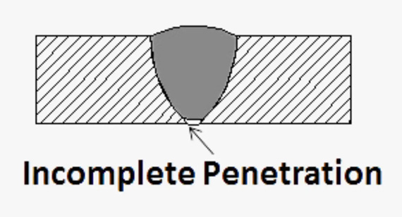
Lack of penetration, also known as incomplete penetration, occurs when the weld metal does not fully fuse with the base metal, resulting in a weak joint. This defect can significantly reduce the strength and integrity of the weld, making it susceptible to failure under load.
Appearance
Lack of penetration is typically visible as an incomplete fusion between the weld bead and the base metal. It may appear as a gap or a shallow weld bead that does not extend fully into the joint.
Possible Consequences
The consequences of lack of penetration include:
Causes of Lack of Penetration
Lack of penetration can be caused by:
How to Repair Lack of Penetration
To repair lack of penetration, follow these steps:
4. Incomplete Fusion or Incomplete Fusion
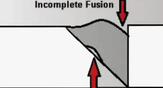
Incomplete fusion occurs when the weld metal does not fully fuse with the adjacent weld bead or the base metal, creating a weak bond within the weld. This defect can lead to reduced weld strength and increased susceptibility to failure under stress.
Appearance
Incomplete fusion appears as gaps or voids within the weld bead, where the weld metal does not properly adhere to the adjacent material. These gaps can be detected through visual inspection or non-destructive testing methods.
Possible Consequences
The consequences of incomplete fusion include:
Causes of Incomplete Fusion
Incomplete fusion can result from:
How to Fix Incomplete Fusion
To fix incomplete fusion, take the following actions:
5. Undercut
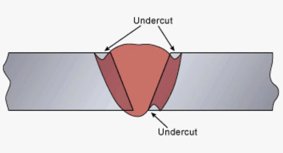
Undercut is a welding defect characterized by a groove or depression along the edges of the weld bead, where the base metal is eroded away. This defect can weaken the weld and reduce its load-bearing capacity.
Appearance
Undercut appears as a narrow, V-shaped groove along the edge of the weld bead, creating an uneven surface where the base metal is not fully fused with the weld.
Possible Consequences
The consequences of undercut include:
Causes of Undercut
Undercut is typically caused by:
How to Fix Undercut
To fix undercut, follow these steps:
6. Spatter
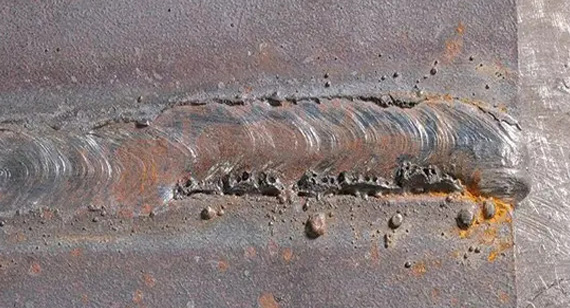
Spatter consists of small droplets of molten metal that are expelled from the welding arc and adhere to the surrounding surfaces. While minor spatter is common, excessive spatter can lead to defects in the weld and surrounding areas.
Appearance
Spatter appears as small, irregular droplets of metal scattered around the weld area, creating a rough and uneven surface.
Possible Consequences
The consequences of spatter include:
Causes of Spatter
Spatter can be caused by:
How to Fix Spatter
To fix spatter, implement the following solutions:
7. Slag Inclusions
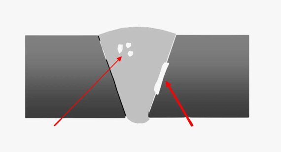
Slag inclusions are non-metallic solid materials that become trapped within the weld metal during the welding process. Slag is a byproduct of the welding process that should be removed before the weld solidifies.
Appearance
Slag inclusions appear as black or dark-colored patches within the weld bead, indicating the presence of trapped slag material.
Possible Consequences
The consequences of slag inclusions include:
Causes of Slag Inclusions
Slag inclusions are caused by:
How to Fix Slag Inclusions
To fix slag inclusions, take the following steps:
8. Cracks
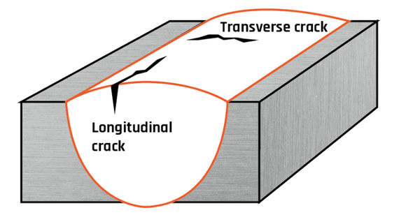
Cracks are fractures that occur within the weld or the heat-affected zone, compromising the strength and integrity of the weld. Cracks can significantly reduce the load-bearing capacity of the welded joint, making it susceptible to failure under stress.
Appearance
Cracks appear as visible lines or fractures within the weld bead or along the joint, often extending into the base metal.
Possible Consequences
The consequences of cracks include:
Causes of Cracks
Cracks are caused by:
How to Fix Cracks
To fix cracks, follow these steps:
9. Porosity
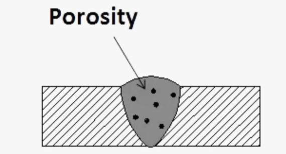
Porosity refers to the presence of small holes or voids within the weld metal, caused by trapped gas during the welding process. These voids can weaken the weld and reduce its overall strength.
Appearance
Porosity appears as small, round holes or bubbles within the weld bead, creating a rough and uneven surface.
Possible Consequences
The consequences of porosity include:
Causes of Porosity
Porosity is caused by:
How to Fix Porosity
To fix porosity, implement the following measures:
10. Overlap
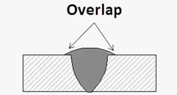
Overlap is a welding defect where the weld bead extends beyond the joint, causing the weld metal to lay on top of the base metal without proper fusion. This creates a weak bond and can lead to reduced weld strength.
Appearance
Overlap appears as excess weld metal that flows over the edge of the joint, creating a flat or bulging area where the weld does not properly fuse with the base metal.
Possible Consequences
The consequences of overlap include:
Causes of Overlap
Overlap is caused by:
How to Fix Overlap
To fix overlap, implement the following solutions:
11. Warp
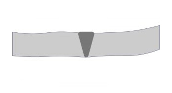
Warp refers to the distortion or bending of the welded component caused by uneven heating and cooling during the welding process. This defect can result in misalignment and dimensional inaccuracies in the final product.
Appearance
Warp appears as a bent or twisted component where the weld has caused uneven expansion and contraction, leading to a non-flat or non-aligned surface.
Possible Consequences
The consequences of warp include:
Causes of Warp
Warp is caused by:
How to Fix Warp
To fix warp, implement the following measures:
12. Burn Through
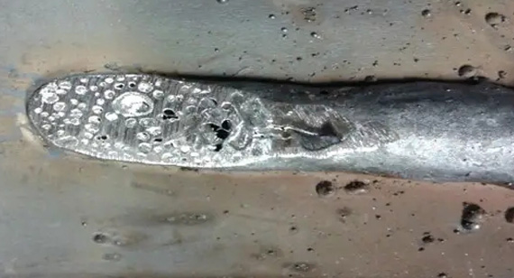
Burn through is a welding defect where excessive heat input causes the weld metal to penetrate too deeply, leading to perforation or thinning of the base metal. This defect can weaken the joint and create leaks or structural weaknesses.
Appearance
Burn through appears as a hole or significantly thinned area in the base metal where the weld has penetrated excessively.
Possible Consequences
The consequences of burn through include:
Causes of Burn Through
Burn through is caused by:
How to Fix Burn Through
To fix burn through, follow these steps:
13. Overroll/Overlap

Overroll, also known as overlap, is a welding defect where the weld bead flows over the edge of the joint without proper fusion. This creates an uneven and weak connection, reducing the overall strength of the weld.
Causes of Overroll
Overroll is caused by:
Prevent Overroll
To prevent overroll, implement the following measures:
14. Laminar Tearing
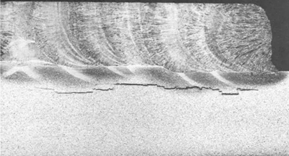
Laminar tearing is a welding defect characterized by thin, tear-like fractures that occur parallel to the weld surface. These defects can weaken the weld and reduce its load-bearing capacity.
Causes of Laminar Tearing
Laminar tearing is caused by:
Prevent Laminar Tearing
To prevent laminar tearing, consider the following solutions:
15. Distortion
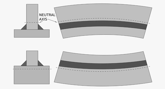
Distortion refers to the warping or bending of the welded component due to uneven heating and cooling during the welding process. This defect can lead to dimensional inaccuracies and misalignment of the welded parts.
Causes of Distortion
Distortion is caused by:
How to Prevent Distortion
To prevent distortion, implement the following measures:
16. Mechanical Damage
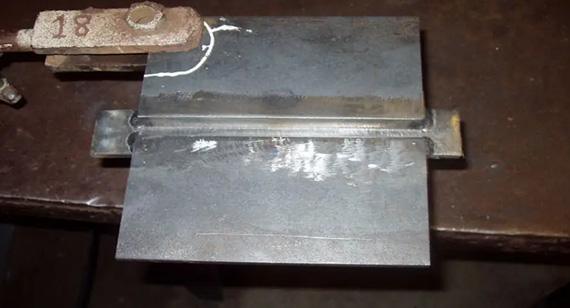
Mechanical damage refers to physical injuries or deformities in the weld or base metal caused by external forces during the welding process. This damage can include scratches, dents, or other surface imperfections that compromise the integrity of the weld.
Causes of Mechanical Damage
Mechanical damage is caused by:
How to Prevent Mechanical Damage
To prevent mechanical damage, follow these steps:
17. Over-Reinforcement
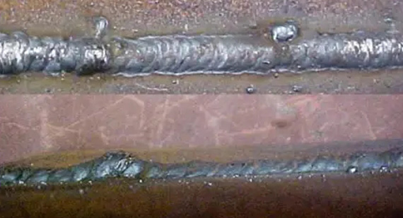
Over-reinforcement is a welding defect where excessive weld metal is deposited, leading to an overly thick weld bead. This defect can cause stress concentrations and reduce the flexibility of the welded joint.
Causes of Over-Reinforcement
Over-reinforcement is caused by:
Prevent Over-Reinforcement
To prevent over-reinforcement, implement the following solutions:
18. Whiskers
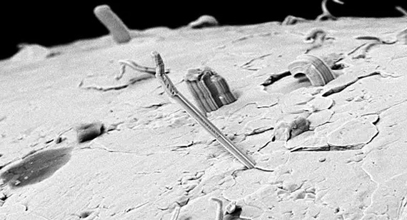
Whiskers is a welding defect characterized by the formation of protrusions or irregularities along the edge of the weld bead. These protrusions can create uneven surfaces and weaken the weld joint.
Causes of Whiskers Formation
Whiskers formation is caused by:
Prevent Whiskers
To prevent whiskers formation, consider the following measures:
19. Misalignment
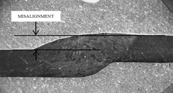
Misalignment refers to the improper alignment of the welded components, resulting in an uneven or off-center weld joint. This defect can lead to weak connections and compromised structural integrity.
Causes of Misalignment
Misalignment is caused by:
Prevent Misalignment
To prevent misalignment, implement the following solutions:
Invisible weld defects, those that are hidden beneath the surface of the weld, can significantly impact the strength and reliability of the welded joint. Detecting these defects is crucial for ensuring the integrity of CNC machining parts and preventing potential failures. Nondestructive Testing (NDT) and Inspection techniques are essential tools for identifying and assessing these hidden flaws without damaging the weld.
Nondestructive Testing (NDT)
Nondestructive Testing (NDT) encompasses a range of inspection methods used to evaluate the integrity of welds without altering or damaging the material. These techniques allow for the detection of internal and surface defects, ensuring that the weld meets the required quality standards.
Magnetic Particle Testing
Magnetic Particle Testing (MPT) is an NDT method used to detect surface and near-surface defects in ferromagnetic materials. The process involves magnetizing the material and applying magnetic particles to the surface. Defects such as cracks and discontinuities disrupt the magnetic field, causing the particles to accumulate at the defect location, making it visible under appropriate lighting conditions.
Ultrasonic Testing - Phased Array
Ultrasonic Testing (UT) using phased array technology is an advanced NDT method that provides detailed images of internal weld defects. This technique involves sending ultrasonic waves into the material and analyzing the reflected signals to identify flaws such as porosity, cracks, and inclusions. Phased array UT offers high accuracy and resolution, making it suitable for inspecting complex welds in CNC machining parts.
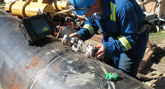
Radiographic Testing
Radiographic Testing (RT) uses X-rays or gamma rays to create images of the internal structure of the weld. This method is effective for detecting internal defects such as voids, inclusions, and cracks that are not visible through other NDT methods. Radiographic Testing provides a permanent record of the weld quality, allowing for thorough inspection and documentation.
Determining whether an irregularity in the weld is a mere discontinuity or a significant defect involves assessing the nature, location, and impact of the flaw. Weld discontinuities are natural imperfections that occur during the welding process and may not necessarily compromise the weld's integrity. On the other hand, weld defects are serious flaws that affect the strength and performance of the weld.
To differentiate between the two:
The future of welding, Nondestructive Testing (NDT), and Nondestructive Evaluation (NDE) is poised for significant advancements driven by technological innovations and evolving industry demands. As manufacturing processes become more sophisticated, the need for precise and reliable welding and inspection techniques continues to grow, especially in the context of CNC machining services and custom CNC machining projects.
Advancements in automation and robotics are transforming the welding industry, enabling more consistent and high-quality welds with reduced human intervention. Automated welding systems equipped with artificial intelligence (AI) and machine learning algorithms can optimize welding parameters in real-time, minimizing defects and enhancing weld quality. This shift towards automation not only improves efficiency but also ensures greater repeatability and precision in the production of CNC machining parts.
In the realm of NDT and NDE, emerging technologies such as digital imaging, advanced sensor systems, and real-time data analysis are revolutionizing inspection processes. These innovations allow for more accurate and comprehensive detection of weld defects, enabling proactive maintenance and quality control. Techniques like phased array ultrasonic testing, digital radiography, and infrared thermography are becoming more prevalent, offering higher resolution and faster inspection times.
Moreover, the integration of NDT and NDE with Industry 4.0 concepts is facilitating smarter and more connected manufacturing environments. The use of cloud-based platforms and the Internet of Things (IoT) enables seamless data sharing and remote monitoring of weld quality, enhancing decision-making and operational efficiency in CNC machining factories.
As sustainability and environmental considerations become increasingly important, future welding practices will also focus on reducing energy consumption and minimizing waste. Eco-friendly welding materials and processes, coupled with efficient recycling methods, will play a crucial role in promoting sustainable manufacturing practices.
In summary, the future of welding, NDT, and NDE is set to be shaped by technological advancements, automation, and a focus on quality and sustainability. These developments will enhance the capabilities of CNC machining services, ensuring the production of high-quality, reliable CNC machining parts that meet the ever-evolving demands of various industries.
Welding defects are a significant concern in the manufacturing of CNC machining parts, as they can compromise the strength, reliability, and functionality of the final product. Understanding the 19 common welding defect types, their causes, and effective solutions is essential for maintaining high-quality standards in CNC machining services. By implementing proper welding techniques, selecting appropriate materials, and utilizing advanced Nondestructive Testing (NDT) methods, manufacturers can identify and address defects early in the production process, ensuring the integrity and performance of their CNC machining parts.
Addressing welding defects not only enhances the durability and safety of products but also reduces production costs and increases efficiency by minimizing the need for rework and repairs. Whether you’re engaged in custom CNC machining, operating within a CNC machining factory, or handling CNC prototype machining, a thorough understanding of welding defects and their mitigation is crucial for achieving excellence in manufacturing.
At VMT CNC Machining Services, we prioritize quality and precision in every aspect of our production process. Our expertise in welding and advanced NDT techniques ensures that our CNC machining parts meet the highest standards of performance and reliability. Partner with us to benefit from our commitment to excellence, leveraging our knowledge of welding defects to deliver superior CNC machining solutions tailored to your specific needs.
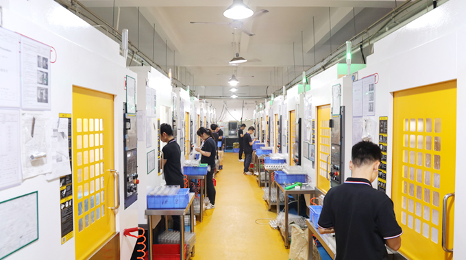
VMT CNC Machining Services is dedicated to providing top-quality CNC machining parts and custom CNC machining solutions for a wide range of industries. Our state-of-the-art CNC machining factory is equipped with the latest technology and staffed by skilled professionals who are experts in precision welding and advanced manufacturing techniques. We understand the critical role that welding plays in the production of durable and reliable CNC machining parts, and we employ rigorous quality control measures to ensure that every weld meets our stringent standards.
Our commitment to excellence extends to our use of advanced Nondestructive Testing (NDT) and Nondestructive Evaluation (NDE) methods, allowing us to detect and address welding defects before they impact the performance of your CNC machining parts. Whether you require CNC prototype machining for testing and development or large-scale production runs for commercial manufacturing, VMT has the expertise and resources to deliver high-quality, defect-free parts that meet your exact specifications.
By partnering with VMT CNC Machining Services, you gain access to a team of dedicated professionals who prioritize quality, efficiency, and customer satisfaction. Our comprehensive approach to welding and defect prevention ensures that your CNC machining projects are completed with the highest level of precision and reliability, driving success and innovation in your manufacturing endeavors.
What Other Types of Weld Defects Are There?
In addition to the 19 common welding defects discussed, other types include incomplete joint penetration, joint misalignment, and surface imperfections. Each defect type has its own causes and solutions, contributing to the overall complexity of welding quality control.
How Do I Tell If It Is a Weld Discontinuity or a Weld Defect?
Determining whether an irregularity is a weld discontinuity or a weld defect involves assessing the nature, location, and impact of the flaw. Discontinuities are natural imperfections that may not compromise weld integrity, while defects are serious flaws that weaken the weld and require corrective action.
What Are the Three Types of Defects That Welders Need to Watch Out For?
Welders need to watch out for surface defects (such as cracks and spatter), internal defects (such as porosity and slag inclusions), and dimensional defects (such as warping and distortion). Each type of defect can impact the quality and reliability of the weld.
What Is the Difference Between a Defect and an Imperfection?
A defect is a flaw that compromises the strength and integrity of the weld, leading to potential failure. An imperfection is a minor irregularity that does not significantly affect the weld’s performance or reliability.
What Are the Two Main Types of Weld Repairs?
The two main types of weld repairs are re-welding (removing and reapplying weld metal) and grinding (removing defects from the weld surface). Re-welding addresses internal defects, while grinding is used for external defects.
Which 3 Common Metals Can Be Welded?
The three common metals that can be welded are steel, aluminum, and stainless steel. Each metal requires specific welding techniques and parameters to achieve strong and reliable welds.
What Is the Easiest Metal to Weld?
The easiest metal to weld is mild steel, due to its low carbon content and good ductility, making it highly malleable and easy to join using various welding techniques.
Which Metal Is Difficult to Weld?
Titanium is considered difficult to weld because it requires an inert atmosphere to prevent contamination and is highly sensitive to oxygen and nitrogen, which can cause brittleness and defects.
What Metals Cannot Be Welded?
Some metals that are difficult or nearly impossible to weld include lead, mercury, and certain high-alloyed metals that react adversely to welding conditions, making reliable welds challenging to achieve.
Why Do Small Holes Appear in My Weld?
Small holes in a weld, known as porosity, can appear due to trapped gases during the welding process. Causes include contaminants on the weld surface, inadequate shielding gas coverage, and improper welding parameters.
What Does Undercut Mean When Welding?
Undercut refers to a welding defect where the weld bead recedes into the base metal along the weld joint, creating a groove or depression that weakens the joint and increases the risk of failure.
This comprehensive guide on welding defects aims to equip you with the knowledge needed to identify, understand, and prevent common issues in your CNC machining projects. By implementing the solutions outlined, you can enhance the quality and reliability of your welds, ensuring that your CNC machining parts meet the highest standards of performance and durability.
