16 years one-stop China custom CNC machining parts factory

Hey there I’m VMT Sam!
With 25 years of CNC machining experience we are committed to helping clients overcome 10000 complex part-processing challenges all to contribute to a better life through intelligent manufacturing. Contact us now
 505 |
Published by VMT at Oct 16 2026 | Reading Time:About 6 minutes


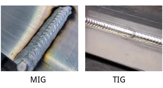
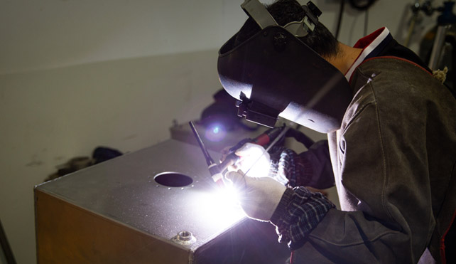
Welding is an essential process in the manufacturing industry, used to join metal components together in a durable and long-lasting way. Among the various welding techniques available, MIG (Metal Inert Gas) and TIG (Tungsten Inert Gas) welding are the two most popular methods. Both techniques are used across a wide range of industries, including automotive, aerospace, construction, and CNC precision machining. MIG welding excels at rapid, continuous production and joining thicker sections cost-effectively, whereas TIG welding provides superior arc control, flawless aesthetic finishes, and ultra-precise leak-tight seals for critical components.
This article provides a detailed comparison of MIG welding vs. TIG welding, outlining the key differences, applications, advantages, and limitations of each method. By understanding the strengths and weaknesses of MIG and TIG welding, manufacturers can make informed decisions when choosing the best welding technique for their specific needs.
Case Overview
At the end of this guide, we will also share a case study showcasing how we completed the CNC machining of 304 stainless steel exhaust flanges, achieving a flatness <= 0.05 mm, linear tolerance ±0.05 mm, position tolerance ±0.10 mm, sealing surface Ra 1.6 μm, and outer diameter Ra 3.2 μm, followed by expert TIG welding to ensure a smooth interior weld seam (addressing the client's previous supplier issue where the TIG welds were uneven, being higher on one side than the other).
MIG and TIG welding are both arc welding processes that use electricity to create the heat required for welding. Despite their similarities, they differ significantly in terms of their power sources, materials, and the techniques involved. Here's a breakdown of the main differences between the two welding methods:
Comparison Table: MIG Welding vs. TIG Welding
| Comparison | MIG Welding (GMAW) | TIG Welding (GTAW) |
| Power Source and Output | Constant Voltage (CV) • Voltage: 15V – 30V • Amperage: 60A – 250A+ |
Constant Current (CC) • Voltage: 10V – 25V • Amperage: 5A – 200A+ |
| Welding Speed and Productivity | Rating: ★★★★★ (High) • Travel Speed: 30 – 60+ inches/min • Ideal for continuous production |
Rating: ★★☆☆☆ (Low/Slow) • Travel Speed: 3 – 10 inches/min • Slower, meticulous process |
| Operator Skill Required | Rating: ★★★☆☆ (Moderate) • Faster learning curve, semi-automatic wire feed |
Rating: ★★★★★ (Advanced) • Requires high dexterity, two-handed coordination |
| Cost Factors | Cost Level: | Cost Level: $$ (High) • Higher equipment/torch investment • Pricier tungsten electrodes and filler rods |
| Material Thickness Suitability | • Best for: Medium to thick metals (>1.0 mm to heavy plate) • High heat input |
• Best for: Thin sheets and precision parts (0.5 mm – 3.0 mm+) |
| Weld Quality and Aesthetics | Rating: ★★★☆☆ (Functional) • Minor spatter, visible transition, requires post-weld cleanup |
Rating: ★★★★★ (Superior) • Zero spatter, smooth fish-scale ripples, premium aesthetic finish |
| Shielding Gas and Cooling | • Gas: Argon + CO2 mix • Cooling: Air-cooled standard (Water-cooled for heavy duty) |
• Gas: Pure Argon or Argon/Helium • Cooling: Air-cooled (light) or Water-cooled (industrial) |
1. Power Source
MIG welding typically uses a constant voltage power source, making it more suitable for welding thicker materials. On the other hand, TIG welding uses a constant current power source, which provides more precise control over the welding arc. This allows TIG welding to excel in applications where precision is critical, especially for thin metals.
2. Material Compatibility and Thickness
MIG welding is more versatile when it comes to the types of materials it can handle. It works well with a range of metals, including steel, aluminum, and copper alloys. MIG welding is best suited for thicker materials due to its high heat input. In contrast, TIG welding is ideal for thinner materials such as stainless steel, aluminum, and titanium. Its ability to create clean, precise welds makes it perfect for applications where weld aesthetics and quality are paramount.
3. Type of Electrode Used
In MIG welding, a consumable wire electrode is fed through the welding gun, which melts and becomes part of the weld pool. TIG welding, on the other hand, uses a non-consumable tungsten electrode, which heats the metal without melting itself. A filler rod may be used in TIG welding, but it’s not always necessary. The use of a non-consumable electrode in TIG welding gives it more control over the weld.
4. Type of Shielding Gas
Both MIG and TIG welding require the use of shielding gas to protect the weld area from contamination by atmospheric gases such as oxygen and nitrogen. MIG welding commonly uses a mix of argon and carbon dioxide, whereas TIG welding typically uses pure argon or a mixture of argon and helium. The choice of shielding gas affects the quality and stability of the weld, with TIG welding providing a more refined shielding environment for precision work.
5. Gun Cooling System
MIG welding guns are generally air-cooled, which makes them suitable for short welding jobs or non-intensive applications. For longer, high-heat welding tasks, water-cooled MIG guns may be used. TIG welding torches are often air-cooled for light-duty work, but water-cooled systems are more common in industrial applications where prolonged welding is required.
6. Quality of Welded Parts
TIG welding is known for producing cleaner, higher-quality welds with minimal spatter. The process is slower but results in aesthetically pleasing welds with superior strength and integrity. MIG welding is faster and more suited to applications that prioritize speed over precision. However, MIG welds may produce more spatter and are generally less refined than TIG welds, especially in critical applications.
7. Productivity
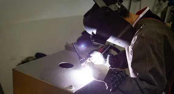
MIG welding is generally more productive than TIG welding due to its faster speed and automation capabilities. MIG welding is often semi-automatic or fully automatic, making it ideal for long production cycles and mass production. TIG welding, while more precise, is slower and requires greater operator skill, which limits its productivity in high-volume production environments.
8. Cost
In terms of initial equipment costs, MIG welding is typically more affordable than TIG welding. The consumables used in MIG welding, such as wire electrodes, are also less expensive than the tungsten electrodes and filler rods used in TIG welding. However, the longer time required for TIG welding may increase labor costs, especially in projects requiring large volumes of welding.
Both MIG and TIG welding can be used on a variety of metals materials, but each technique has its strengths depending on the material being welded.
Stainless Steel
For stainless steel, TIG welding is generally preferred due to its ability to produce clean, precise welds with minimal contamination. TIG welding’s slower process gives the operator better control, resulting in aesthetically pleasing, high-strength welds. MIG welding, while faster, may produce more spatter and is often used when speed is a priority.
Mild Steel and Cast Iron
MIG welding is ideal for mild steel and cast iron, as it provides a fast and efficient method for joining these materials. The high heat input and faster welding speed make MIG welding suitable for thicker sections of steel, commonly used in construction and heavy manufacturing.
Aluminum
When welding aluminum, TIG welding is often the preferred method because it provides more control over the heat input, which is critical for preventing warping and distortion in thin aluminum sheets. However, MIG welding is also used for aluminum, particularly for thicker pieces where speed is a priority.
Titanium
For titanium and its alloys, TIG welding is virtually mandatory. Because titanium is highly reactive at elevated temperatures and prone to embrittlement from atmospheric contamination, TIG welding, supported by rigorous inert gas shielding (including trailing shields), provides the precise atmosphere control required. MIG is rarely recommended for titanium due to the high risk of oxidation and weld degradation.
Copper and Copper Alloys
Copper and its alloys (such as brass and bronze) possess extremely high thermal conductivity, meaning heat dissipates rapidly away from the weld zone. TIG welding is excellent for thinner copper components when paired with proper preheating to manage heat loss. For thicker copper sections, MIG welding is often utilized because the continuous wire feed helps overcome high thermal conductivity by delivering a steady, high-energy input.
Galvanized Steel
MIG welding is frequently chosen for galvanized steel in sheet metal and automotive fabrication because its speed helps minimize the breakdown of the protective zinc coating. TIG welding galvanized steel can be challenging; the intense localized heat vaporizes the zinc coating violently, causing porosity and unstable arcs unless the zinc is meticulously ground off prior to welding.
Summary Table: Best Welding Method by Material
| Material | Preferred Method | Engineering Consideration |
| Stainless Steel | TIG Welding (Best for quality) MIG (For speed) |
TIG delivers clean, corrosion-resistant, high-aesthetic joints with zero spatter; MIG is used for faster production. |
| Mild Steel and Cast Iron | MIG Welding | High deposition rate, excellent for thick sections, structural fabrication, and cost-effective production. |
| Aluminum | TIG Welding (Thin sheets) MIG Welding (Thick plates) |
TIG prevents distortion and controls heat on thin gauges; MIG provides high speed on thicker structural aluminum. |
| Titanium | TIG Welding Only | Essential for preventing atmospheric contamination and embrittlement through precise gas shielding. |
| Copper and it’s Alloys | TIG (Thin) / MIG (Thick) | TIG with preheating for precision parts; MIG's continuous feed helps compensate for high thermal conductivity on thick parts. |
| Galvanized Steel | MIG Welding | Faster travel speed reduces zinc burn-off and coating degradation compared to slower TIG welding. |
The components involved in TIG and MIG welding differ in terms of power supply, electrodes, and other equipment.
1. TIG Welding Components
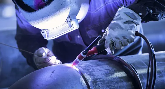
Power:TIG welding uses a constant current power source, allowing for precise control of the welding arc, which is critical for delicate welding tasks.
Torch:The torch in TIG welding holds a tungsten electrode and directs the shielding gas to the weld area. It can be either air-cooled or water-cooled, depending on the welding task.
Foot Pedal:TIG welding often includes a foot pedal to control the amperage, giving the welder more control over the heat input.
Electrode and Shielding Gas:TIG welding uses a non-consumable tungsten electrode and typically relies on argon or a mix of argon and helium as the shielding gas.
Filler Material:Filler material is used as needed in TIG welding and is manually fed into the weld pool.
Support Rod:A support rod may be used for additional reinforcement, particularly when welding thicker materials.
2. MIG Welding Components
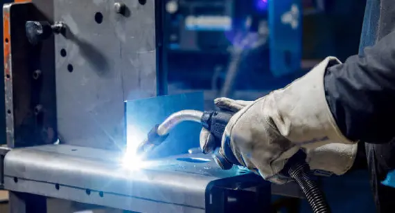
Power Supply:MIG welding uses a constant voltage power supply, which provides the high heat required for welding thicker materials.
Wires:A consumable wire is fed continuously through the MIG gun, acting as both the electrode and the filler material.
Electrode:The consumable electrode in MIG welding is a metal wire that melts into the weld pool to join the two metal pieces.
Torch:The MIG torch directs the wire electrode and shielding gas onto the weld area. MIG torches are generally air-cooled, but water-cooled options are available for more intensive applications.
Shielding Gas:MIG welding typically uses a blend of argon and carbon dioxide to shield the weld area from contaminants.
Principles of TIG Welding
TIG welding uses a non-consumable tungsten electrode to create an arc that heats the metal. The process may or may not require filler material, depending on the type of weld being performed. A shielding gas, typically argon, is used to protect the weld from contamination.
Advantages of TIG Welding
Disadvantages of TIG Welding
Applications of TIG Welding
Principles of MIG Welding
In MIG welding, a consumable wire electrode is continuously fed through the welding gun and melts into the weld pool. The process is shielded by an inert gas, typically a mixture of argon and carbon dioxide, which protects the weld from contaminants.
Advantages of MIG Welding
Disadvantages of MIG Welding
Applications of MIG Welding
Examining weld appearance and structural consistency is one of the most effective ways to judge supplier craftsmanship. To help you distinguish between exceptional fabrication and substandard workmanship, refer to the following inspection items for both TIG and MIG welding.
1. TIG Welding Quality Inspection
TIG welding is prized for its precision and aesthetics. When reviewing TIG-welded components, inspect them against the following criteria:
| Inspection Item | Premium TIG Weld Appearance | Defective / Poor TIG Weld Appearance |
| Overall Color | Bright silver, light straw/gold, with minimal pale purple tint. | Dark gray, pitch black, or matte surface with heavy oxidation. |
| Bead Ripple Pattern | Fine, closely spaced fish-scale ripples with uniform pitch and smooth transitions. | Coarse, irregular ripples, or completely smooth with no visible ripple pattern. |
| Edge Transition | Smooth, gradual transition blending seamlessly into the flange or tube wall. | Deep, sharp grooves along the edges (undercutting) or visible gaps. |
| Surface Integrity | Mirror-smooth finish, free of any surface inclusions, cracks, or impurities. | Pitting, pinholes, porosity, or black slag residue trapped on the surface. |
| Flange Flatness and Fit | Perfect, tight-fitting joints with exceptional alignment and zero distortion. | Warped flanges, noticeable gaps, or visible misalignment to the naked eye. |
2. MIG Welding Quality Inspection
MIG welding is built for speed and efficiency, but quality execution still requires strict parameter control. Look out for these indicators during your evaluation:
| Inspection Item | Premium MIG Weld Appearance | Defective / Poor MIG Weld Appearance |
| Overall Color | Silver or light gold (achieved via proper gas shielding, free of heavy carbonization). | Pitch black or dark gray, covered with a thick layer of heavy black oxide scale. |
| Metal Spatter (Key Indicator) | Exceptionally clean surface with virtually zero scattered metallic droplets. | The area surrounding the weld is heavily covered in hard, stubborn metal spatter beads. |
| Weld Profile and Shape | Flat, smooth profile blending naturally with base metals (gentle concave or low convex contour). | Heavily mounded bead ("stacking up") or overflowing past the joint boundaries. |
| Ripple Texture | Tight, consistent ripple pattern—while less pronounced than TIG, it remains smooth and uniform. | Coarse, chaotic texture, or a rough, unrefined solid chunk appearance with no consistent flow. |
| Edge Integration | Clean edge definition with zero depressions or sink marks. | Severe undercutting (grooves) or visible gaps/lack of fusion between the weld and parent part. |
To dive deeper into the technical causes behind these defects, learn how to optimize welding parameters, or require reliable, high-precision welding services that meet these exact quality standards, you can reach out to our engineering team. We are always glad to assist you with your project requirements.
Precision CNC Machining (Flatness <= 0.05 mm) and Advanced TIG Welding for 304 Stainless Steel Exhaust Flanges
In high-performance automotive exhaust systems, component durability under high thermal and mechanical stress is essential. A client came to us seeking to resolve recurring quality inconsistencies from their previous manufacturing supplier for 304 stainless steel exhaust flanges. The former process resulted in asymmetric TIG weld seams that were higher on one side than the other. This uneven weld profile restricted internal gas flow and increased the defect rate during stress testing under elevated pressure and temperature.
To establish a stable geometric foundation, our engineering team first optimized the multi-axis CNC machining process for the 304 stainless steel flanges. We utilized specialized soft-jaw setups and multi-stage rough-to-finish toolpaths to allow internal stress relief without deforming the flange face. Advanced carbide tooling with high-pressure coolant delivered smooth surface finishes, strictly controlling material removal and thermal expansion. Consequently, every part achieved exceptional precision across production batches: Flatness <= 0.05 mm, Linear Tolerance ±0.05 mm, Position Tolerance ±0.10 mm, sealing surface Ra 1.6 μm, and outer diameter Ra 3.2 μm.
Following precision machining, our certified welders executed optimized TIG welding techniques tailored for stainless steel components. To eliminate internal weld bead unevenness, we applied high-purity argon back-purging to support the root pass, preventing internal oxidation and sagging during penetration. Using pulsed TIG current, our welders maintained precise arc-length control, spreading heat evenly around the circumference. This refined technique eliminated internal flow restrictions, optimized exhaust gas velocity, and provided structural strength to resist cracking during thermal expansion cycles.
By combining tight-tolerance CNC machining with refined TIG welding, we resolved the weld profile variations and reduced defect rates to zero. The completed exhaust flange assemblies successfully met all sealing, alignment, and durability standards, delivering smooth internal airflow and long-term operating reliability for the client.
This article has outlined the core differences, material compatibilities, and quality inspection techniques for MIG and TIG welding, along with the precise manufacturing solution required to achieve an excellent flatness and smooth interior weld seams on 304 stainless steel components ( maintaining a flatness <= 0.05 mm and smooth, turbulence-free internal weld seams). Also with many considerations, you can understand how to balance welding speed, aesthetic finish, and tight geometric tolerances, while equipping yourself with practical standards to evaluate manufacturing craftsmanship. For problem like solving recurring weld inconsistencies, high defect rates , or get expert guidance on your custom metal fabrication projects, feel free to contact our engineering team. We are always glad to review your specifications and provide reliable, high-precision manufacturing solutions.
Send your 2D drawings, 3D CAD models, material, welding method, tolerance requirements, weld appearance requirements, prototype quantity and production quantity. VMT will review CNC machining, MIG or TIG welding, DFM, inspection and quotation requirements.
All information and uploaded files are secure and confidential.
1 Tell us what you need
2 Get solution & quote
3 Approve production
Email: inquiry@vimetal.com.cn
What are the main differences between MIG welding and TIG welding?
The primary differences are in the power source, electrode type, speed, and material compatibility. TIG is more precise but slower, while MIG is faster and better suited for thicker materials.
Is MIG or TIG better for welding aluminum?
TIG welding is generally preferred for aluminum because it provides better control over the heat input, which is important for preventing warping.
Should I choose riveting instead of welding?
Riveting may be a better option for some applications where welding is not feasible or if disassembly is required in the future.
Is TIG welding more difficult than MIG welding?
Yes, TIG welding is more difficult to master due to the level of precision and control required.
Which is better, MIG welding or TIG welding?
It depends on the application. MIG is better for high-volume, thicker materials, while TIG is better for precision work and thin metals.
What metals cannot be welded?
Metals such as cast iron, certain high-carbon steels, and some alloys may be difficult or impossible to weld effectively.
Can MIG weld aluminum?
Yes, MIG can weld aluminum, though TIG welding is often preferred for thin aluminum sheets.
The technical information and manufacturing advice shared on the VMT website are for general guidance only. While we strive for accuracy, VMT does not guarantee that the processes, tolerances, or material properties mentioned are applicable to every specific project. Any reliance you place on such information is strictly at your own risk. It is the buyer's responsibility to provide definitive engineering specifications for any production orders. Final specifications and service terms shall be subject to the formal contract or quotation confirmed by both parties.


 +86 15099911516




 Read more