16 years one-stop China custom CNC machining parts factory

Hey there I’m VMT Sam!
With 25 years of CNC machining experience we are committed to helping clients overcome 10000 complex part-processing challenges all to contribute to a better life through intelligent manufacturing. Contact us now
 1620 |
Published by VMT at Jun 13 2025 | Reading Time:About 20 minutes
1620 |
Published by VMT at Jun 13 2025 | Reading Time:About 20 minutes


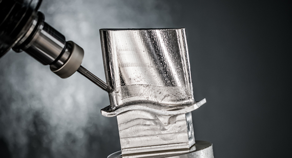
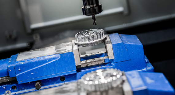
If you’ve ever struggled with fitting CNC machining parts precisely or encountered stress fractures at sharp edges, you’re not alone. In high-precision manufacturing, even the smallest detail—like the edge of a part—can be the difference between success and costly failure. A common, often overlooked solution to these challenges is chamfering. Yet many professionals are still unsure of its function, execution, and benefits.
Chamfering in CNC machining offers a proven way to reduce mechanical stress, improve part safety, and enhance assembly precision. But what exactly is a chamfer, and how does it affect your machining process?
In this guide, we’ll explore everything you need to know about chamfering—from its definition and types to methods, applications, tools, and challenges—so you can create better, safer, and more functional CNC machining parts.
A chamfer is a beveled edge that replaces a 90-degree corner on a machined part, created to reduce sharp edges, improve assembly, and enhance durability. Chamfering in CNC machining is essential for stress relief, safety, precision, and aesthetics, and it is achieved using specialized tools or multi-axis CNC machining services.
Now that you know what a chamfer is in general terms, let’s dive deeper. Why are chamfers so critical in CNC machining services? What roles do they play in the functionality, safety, and aesthetics of CNC machining parts? This guide will walk you through their historical background, primary purposes, key methods, tooling options, and more. Whether you're a designer, machinist, or decision-maker in CNC machining factories, this guide will give you clarity and actionable insights into chamfering.
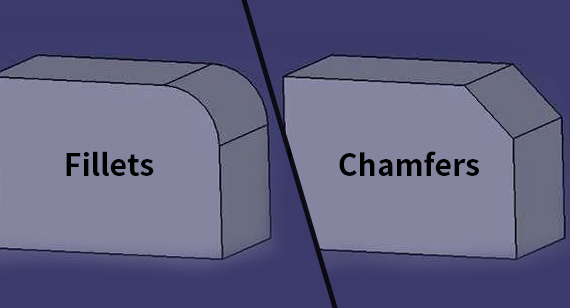
A chamfer is a beveled edge that replaces a sharp, 90-degree corner with an angled cut, typically made at a 45-degree angle, though the angle can vary depending on the design requirements. Unlike a fillet, which rounds the corner, a chamfer creates a flat edge between two intersecting surfaces, softening the transition without fully removing the material. This simple geometric modification serves a variety of purposes in CNC machining, particularly in enhancing the functionality, durability, and appearance of parts.
In CNC machining, chamfers are commonly applied to the edges of parts to address a number of technical and operational challenges. A chamfered edge can help reduce stress concentration, prevent sharp edges that could cause injury or wear during handling, and improve part fit during assembly. Additionally, chamfers can enhance the aesthetic appeal of a product by giving it a more polished, professional look.
Chamfering is used across various industries, from aerospace to automotive, to create parts that are safer, more durable, and easier to assemble. Whether dealing with complex mechanical components or simple fasteners, chamfering plays an integral role in ensuring that parts function as intended and meet quality standards.
In CNC machining, chamfering can be achieved using different tools and techniques, ranging from traditional manual methods to advanced multi-axis CNC machines. The type of chamfer applied, along with the specific angle and depth, depends on the application and the requirements of the part being produced.
In the next section, we will explore how chamfering works in more detail, including the different types of chamfers and the tools used to create them in CNC machining processes.

Chamfering is a machining process that involves cutting away the sharp edges of a part to create a beveled, angled edge. This process can be performed on a variety of materials, including metals, plastics, and composites, using a variety of tools. In CNC machining, chamfering is done with high precision to ensure that the resulting edge meets both functional and aesthetic requirements.
The chamfering process works by removing a portion of the material from the corner of a part at a specific angle, typically between 15 to 45 degrees, although the angle can vary depending on the design specifications. This is done by applying a cutting tool to the edge of the part in a controlled manner. The cutting tool can be a chamfer mill, an end mill, or specialized tools like chamfering inserts or rotary tools, depending on the complexity and material of the part.

Here’s a step-by-step breakdown of how chamfering works in CNC machining:
In addition to these basic steps, chamfering may also involve additional processes, such as deburring, to remove any remaining sharp edges or burrs that could affect the function or appearance of the part. Chamfering is particularly useful when dealing with CNC machining parts that will undergo assembly, as it helps to ensure a smooth and precise fit between components.
Chamfering is often used alongside other CNC machining processes, such as turning, milling, or drilling, to complete the part and prepare it for its final application.
In the next section, we’ll dive into the different types of chamfers used in CNC machining and their specific applications.
The use of chamfers dates back to the early days of mechanical engineering, where the need for more refined, functional, and aesthetically pleasing designs led to the introduction of edge treatments such as chamfering. While the exact timeline of chamfering’s development is unclear, its applications have evolved alongside advancements in manufacturing technology.
In the early stages of industrial machining, parts were crafted manually or with rudimentary tools, often resulting in rough edges that could lead to assembly issues, wear, or even injury. Sharp edges posed problems, especially in the automotive and machinery industries, where parts needed to fit together precisely without damaging other components or harming workers. The solution came in the form of edge treatments, and the chamfer became one of the most widely adopted methods for addressing these issues.
The industrial revolution in the 18th and 19th centuries marked a significant turning point for manufacturing processes, including chamfering. The introduction of precision tools and machinery made it easier to shape parts with greater accuracy, and the concept of chamfering as a standard technique began to take shape. Chamfers were not just practical; they also helped to improve the aesthetics of components, as the beveled edge created a more polished and professional appearance.
By the early 20th century, chamfering tools became more specialized, and manufacturers began to use dedicated chamfer mills and cutters designed to create consistent, accurate chamfered edges. These tools allowed for better control over the angle and depth of the chamfer, which was essential for high-precision applications such as aerospace, automotive, and electronics.
The rise of Computer Numerical Control (CNC) technology in the latter half of the 20th century further revolutionized chamfering. CNC machines brought unparalleled precision, speed, and flexibility to the process. Chamfering, once performed by hand or with simple mechanical machines, could now be executed with tight tolerances and minimal operator intervention. This was particularly important for industries such as aerospace, where even the smallest deviations from specifications could result in catastrophic failures.
As CNC machining became more advanced, the application of chamfering expanded to a wide range of industries, from medical device manufacturing to consumer electronics. The ability to program chamfering into the production cycle allowed for the creation of complex geometries and ensured that parts met strict quality standards.
Today, chamfering is a standard procedure in CNC machining factories around the world. It is an essential part of ensuring that parts are safe, functional, and ready for assembly. Whether it’s a small mechanical component, a precision aerospace part, or an intricate piece of medical equipment, chamfering continues to be a vital technique in modern manufacturing.
The historical development of chamfering reflects broader trends in industrial manufacturing, from the advent of simple tools to the integration of highly automated CNC systems. This evolution has led to increasingly precise and cost-effective ways of improving part quality, safety, and performance—goals that remain just as relevant today as they were in the early days of machining.
Next, we will explore why chamfers are so important in CNC machining and how they contribute to the overall quality and functionality of parts.
Chamfers play a crucial role in CNC machining because they address a variety of practical, safety, and aesthetic challenges that arise during the manufacturing of parts. While chamfering is often considered a simple modification, its impact on the overall functionality and quality of a part cannot be overstated. In fact, chamfers are one of the most commonly used edge treatments in the machining process due to their ability to improve the performance and durability of CNC machining parts.
By removing sharp edges and creating beveled corners, chamfers provide a host of benefits that go beyond mere appearance. Whether it's enhancing safety, improving assembly precision, or reducing mechanical stress, chamfers are an essential feature in high-quality CNC machining parts. Let’s take a closer look at why chamfers are so important in the world of CNC machining.
Why are Chamfers Important?
Chamfers are essential for several reasons, all of which contribute to the overall performance, safety, and quality of CNC machined parts. The importance of chamfers in CNC machining lies in their ability to fulfill specific functional requirements while also improving the efficiency and precision of the machining process. Here are the key reasons why chamfers are widely adopted in the industry:
Reducing Stress
One of the primary reasons for adding chamfers to CNC machining parts is to reduce stress concentrations at sharp corners. When a part has a sharp 90-degree edge, stress tends to accumulate at this point during use, especially when the part is subjected to forces, pressure, or vibrations. Over time, this stress can lead to cracks, material fatigue, and even part failure.
Chamfering helps to redistribute the stress more evenly across the part, reducing the likelihood of these issues. By creating a sloped or angled edge, chamfers lower the peak stress at critical points, increasing the part's overall durability and lifespan. This is particularly important in high-performance applications, such as aerospace and automotive, where even small imperfections can lead to catastrophic results.
Additionally, chamfers can help prevent stress-related issues in parts that are subject to repeated loading and unloading cycles, ensuring they maintain their integrity under pressure. Whether the part is a structural component or a fastener, chamfering ensures it remains strong and resilient throughout its use.
Assembly Enhancement
Chamfering also improves the ease and accuracy of assembling CNC machining parts. When two components need to fit together, such as in the case of bolts and nuts, shafts and bearings, or even complex assemblies in aerospace or automotive systems, chamfered edges make it easier to align and connect the parts.
Without chamfers, sharp edges can cause parts to catch or bind during assembly, leading to difficulties in aligning components or creating tight fits. Chamfers eliminate this problem by creating a smoother transition between surfaces, allowing parts to fit together more easily and accurately. This is particularly beneficial when working with high-precision components that must meet tight tolerances, such as in the medical or electronics industries.
In addition to facilitating assembly, chamfers also help ensure that parts maintain a consistent fit during assembly, even when dealing with mass-produced CNC machining parts. The uniformity provided by chamfering leads to reduced defects, faster assembly times, and fewer chances of errors.
Aesthetic Improvement
While the primary function of chamfers in CNC machining is often related to mechanical performance, they also serve a significant aesthetic purpose. Parts with sharp, unfinished edges tend to look rough and unfinished, giving the final product a less professional appearance. Chamfering softens these edges, creating a more refined and polished look.
For many industries, particularly those dealing with consumer electronics, automotive parts, and high-end machinery, the aesthetic quality of a product is just as important as its functionality. Chamfered edges add a touch of sophistication and professionalism, enhancing the overall look of the product. In some cases, chamfers are even used as part of the design language of a product, creating a distinct visual identity.
Moreover, chamfers can be used creatively to enhance the visual appeal of parts, especially when combined with other surface treatments like anodizing or polishing. The clean, smooth lines created by chamfering can elevate the overall design of a part, making it look more modern, durable, and well-crafted.
In the next section, we’ll dive into the Main Functions of Chamfers and how they contribute to safety, performance, and other key considerations in CNC machining.
Chamfers serve several critical functions in CNC machining, enhancing both the mechanical properties and the aesthetic appeal of parts. While they are primarily designed to improve the functionality and safety of components, chamfers also contribute to the overall efficiency of the manufacturing and assembly process. In this section, we’ll explore the main functions of chamfers in CNC machining, emphasizing their practical benefits and why they are indispensable for high-quality machining parts.
1. Facilitates Assembly
One of the most significant roles of chamfers in CNC machining is their ability to simplify the assembly process. When two parts are designed to fit together, chamfered edges help ease the alignment, making it easier for the components to connect precisely. Sharp edges or corners can make it difficult to align parts during assembly, potentially causing misalignment, binding, or even damaging the components.
Chamfers help prevent these issues by providing a smooth, beveled transition between surfaces, allowing the parts to slide or fit into place more easily. This is especially important in industries like automotive, aerospace, and electronics, where components need to fit together with high precision. The chamfered edges make it possible to achieve tighter tolerances and reduce the chance of defects during assembly, resulting in higher quality products and faster assembly times.
2. Prevents Chipping or Cracking of Edges
In CNC machining, sharp edges are highly susceptible to chipping, cracking, or other forms of damage, especially when the part is exposed to mechanical stress, impact, or friction. By chamfering the edges, the risk of such damage is significantly reduced. Chamfered edges distribute forces more evenly and help to prevent stress concentrations that can cause the edges to fail.
In industries like automotive, where parts are subjected to extreme conditions such as high pressures and vibrations, preventing edge damage is critical to ensuring the longevity and safety of the part. Additionally, chamfering can improve the performance of parts that come into contact with other components during operation, as the beveled edges reduce the potential for wear and tear over time.
3. Improves Operator and User Safety
Sharp edges on CNC machining parts present a safety hazard, especially for operators handling the parts during manufacturing or assembly. In industries where parts are handled frequently, such as in machining factories, tools, or electronics assembly lines, chamfering sharp edges ensures a safer working environment by eliminating the risk of cuts or abrasions.
Chamfers also reduce the likelihood of injury during the final use of a part, particularly in consumer-facing products. For example, in medical devices or consumer electronics, chamfered edges help prevent accidental injuries when users interact with the product. By creating smooth, rounded transitions at critical points, chamfers play a role in both the immediate and long-term safety of a part.
4. Reduces Stress Concentrations
Stress concentrations occur when forces are concentrated in specific areas of a part, often at sharp corners or edges. These areas are more likely to experience fractures or deformations, especially under load or pressure. Chamfering the edges of a part redistributes the forces more evenly, reducing the likelihood of stress build-up at critical points.
By eliminating sharp edges and creating a more gradual transition, chamfers enhance the part's overall durability and resistance to mechanical failure. This is particularly important in industries like aerospace, where parts must withstand high stresses without compromising safety or performance. Chamfers can extend the life of a part by minimizing the risk of fatigue failure, which can be caused by repeated loading cycles.
5. Assists with Coatings and Surface Treatments
Chamfers are beneficial when parts are subjected to surface treatments such as anodizing, painting, or coating. Sharp edges can cause uneven coating thickness or issues with adhesion, leading to defects in the surface treatment. Chamfered edges, on the other hand, promote more uniform coating applications, as they allow coatings to spread evenly across the surface.
In addition, chamfers help reduce the risk of coating chipping or peeling at the edges, which could otherwise affect the part’s performance or appearance. In industries such as automotive and consumer electronics, where surface finish quality is critical, chamfers play an important role in ensuring the durability and consistency of coatings.
6. Enhances Aesthetics and Professional Appearance
Beyond their functional benefits, chamfers significantly enhance the visual appeal of CNC machining parts. Parts with sharp, unfinished edges often appear rough and poorly finished, which can negatively affect the overall impression of the product. Chamfers create a clean, polished look by softening edges and providing a more refined transition between surfaces.
In many industries, such as consumer electronics, automotive, and luxury goods, aesthetics are just as important as functionality. A well-machined part with chamfered edges not only looks more professional but also gives the impression of higher quality. Chamfers help products stand out by creating smooth, elegant lines that are both visually pleasing and indicative of precision craftsmanship.
7. Assists with Measurement and Inspection
Chamfered edges are often easier to measure and inspect than sharp edges. During quality control and inspection, it’s essential to ensure that parts meet specific tolerances, and chamfered edges help inspectors assess dimensions more accurately. The beveled shape allows measurement tools like calipers and micrometers to fit more easily into the corners, making it easier to obtain precise readings.
Moreover, chamfers can simplify the inspection process when checking for features like hole alignment, surface flatness, or edge consistency. By reducing the complexity of the edge geometry, chamfers ensure that the part can be inspected more efficiently, which is crucial for maintaining high-quality standards in industries that require tight tolerances.
Chamfers are a versatile and essential feature in CNC machining, offering a wide range of benefits that improve part performance, safety, and aesthetic quality. As we continue to explore the different methods of chamfering and their applications, we'll look at how chamfers are created in CNC machining and which tools are best suited for the task.
Here's a table summarizing the Main Functions of Chamfers in CNC machining:
| Function |
Description |
| Facilitates Assembly |
Chamfers make it easier to align and fit parts together, reducing the risk of misalignment, binding, or damage during assembly. |
| Prevents Chipping or Cracking of Edges |
Chamfering redistributes stress, preventing sharp edges from chipping, cracking, or experiencing material fatigue under pressure. |
| Improves Operator and User Safety |
By removing sharp edges, chamfers reduce the risk of cuts, abrasions, and other injuries to operators and users handling the parts. |
| Reduces Stress Concentrations |
Chamfers eliminate sharp corners, distributing stress more evenly across the part and preventing stress-related failures. |
| Assists with Coatings and Surface Treatments |
Chamfers help achieve uniform coating applications, ensuring better adhesion and reducing the risk of coating defects such as peeling or chipping. |
| Enhances Aesthetics and Professional Appearance |
Chamfers create smooth, refined edges, improving the overall visual appeal and professional look of the part. |
| Assists with Measurement and Inspection |
Chamfered edges are easier to measure and inspect accurately, enabling more precise quality control and dimensional checks. |
This table summarizes the core functions of chamfers and how they contribute to various aspects of CNC machining, from assembly to quality control.
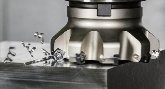
Chamfering in CNC machining can be accomplished through several techniques, each suited for specific applications and machining conditions. The method you choose depends on factors such as the part geometry, material, required precision, and production volume. Understanding the various chamfering methods available allows manufacturers to select the best approach for achieving high-quality results.
Below, we explore one of the most commonly used methods: using chamfer milling cutters, along with its benefits, limitations, and applications.
Using Chamfer Milling Cutters
Chamfer milling cutters are specifically designed tools that allow for the creation of chamfers on parts in CNC machining. These tools are used to cut precise bevels or angled edges on a variety of materials. Chamfer milling cutters are popular in both high-volume production environments and small-scale, custom manufacturing due to their versatility and ability to produce accurate chamfers.
Chamfer milling cutters can be used with different types of CNC milling machines, including vertical and horizontal mills. The cutters are typically designed with a specific angle, allowing operators to achieve consistent and uniform chamfers at the desired angle. These tools are available in various sizes and configurations, making them suitable for a wide range of part geometries.
Benefits
Consistency
Chamfer milling cutters provide high consistency in the chamfering process. The tool's design allows for uniform cutting along the edge, ensuring that the chamfers are identical across multiple parts. This is particularly important in mass production where precision and uniformity are crucial. As a result, chamfer milling cutters help maintain part quality and reduce the likelihood of defects.
Easy Programming
CNC machines that use chamfer milling cutters allow for relatively easy programming. Since these tools are designed to create chamfers at specific angles, the CNC program can be optimized for efficient cutting with minimal adjustments. This leads to faster setup times and reduces the complexity of programming when compared to other methods like manual chamfering.
Speed
Chamfer milling cutters are designed for high-speed cutting, making them an ideal choice for fast production environments. They can remove material quickly, helping to shorten cycle times and increase throughput. In industries where time is a critical factor—such as automotive or electronics manufacturing—speed is a significant advantage, and chamfer milling cutters can help keep operations efficient and cost-effective.
Limitations
Limited to Straight Edges
One of the primary limitations of chamfer milling cutters is that they are typically only effective on straight edges. If the part has curves, intricate contours, or complex geometries, this method may not be suitable without additional tooling or process steps. For more complex parts, specialized tools or multi-axis machining may be required to achieve the desired chamfer.
Tool Wear
Like all cutting tools, chamfer milling cutters are subject to wear over time, particularly in high-volume applications where they are used extensively. Tool wear can affect the quality and accuracy of the chamfers, leading to inconsistencies in the cut. Regular tool inspection and replacement are necessary to maintain performance, but this can increase maintenance costs and downtime.
Best Suited For
Chamfer milling cutters are best suited for the following:
Applications
Chamfer milling cutters are used in various industries and applications, including:
In the next section, we'll explore other chamfering methods, such as using end mills for chamfering, to compare their benefits, limitations, and best applications.
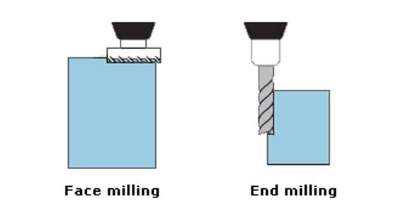
Chamfering with End Mills
End mills are one of the most versatile cutting tools used in CNC machining. While they are primarily designed for milling operations, they can also be employed to create chamfers on parts. Chamfering with end mills is a widely used method due to its adaptability and effectiveness in various applications. This method is suitable for a range of part geometries, and it offers flexibility for machinists working on both simple and complex designs.
End mills are typically used to cut chamfers by running them along the edges of a part at an angle. The versatility of end mills allows for different approaches depending on the desired chamfer size, angle, and part material. By adjusting the CNC programming, end mills can create consistent and high-quality chamfers.
Benefits
Versatility
One of the major advantages of chamfering with end mills is their versatility. End mills come in various shapes and sizes, making them suitable for a wide range of machining tasks. Whether you need a small chamfer on a simple part or a larger chamfer on a complex, multi-featured part, an end mill can be adapted to fit the specific requirements. Additionally, end mills can be used to machine features on both external and internal edges, providing great flexibility in chamfering.
Effectiveness
End mills are highly effective at chamfering because they allow for precise, controlled cutting along the edges. Their ability to cut smoothly and consistently ensures that chamfers are well-defined and accurate. Whether you are working with metals like aluminum, stainless steel, or titanium, end mills provide an efficient method for producing chamfers that meet tight tolerances. This effectiveness is particularly important in industries that require high precision, such as aerospace, automotive, and medical device manufacturing.
Limitations
Programming Complexity
While end mills offer flexibility, one of the challenges of using them for chamfering is the increased complexity in CNC programming. Unlike chamfer milling cutters, which are specialized for creating chamfers, end mills require precise programming to achieve the correct angle and size of the chamfer. This can involve adjusting feed rates, tool paths, and machining parameters to ensure that the chamfer is produced to the desired specifications. As a result, programming for end mills may take more time and expertise compared to other chamfering methods.
Risk of Inconsistency
Another limitation of chamfering with end mills is the potential for inconsistency in the chamfer dimensions. End mills are not always as precise as chamfer milling cutters, especially when machining parts with tight tolerances or when multiple chamfers are required on the same part. The quality of the chamfer can vary depending on tool wear, material properties, and machining parameters, leading to potential issues with consistency. Regular monitoring of tool wear and machine calibration is crucial to minimize this risk.
Best Suited For
Chamfering with end mills is particularly well-suited for:
Applications
Chamfering with end mills is commonly applied in a variety of industries, including:
Next, we will explore CNC turning chamfering, focusing on its benefits, limitations, and applications, to compare it with other methods like end milling and chamfer milling.
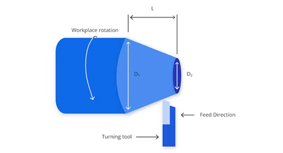
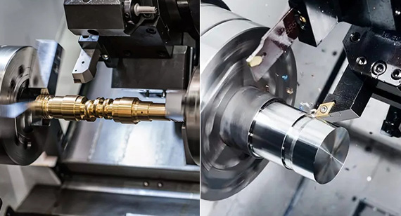
CNC turning chamfering is a process where chamfers are created on rotating cylindrical parts using a CNC lathe machine. This method is widely used in industries that produce parts with a round or cylindrical geometry, such as automotive, aerospace, and manufacturing. Unlike milling-based chamfering methods, turning involves cutting the material as it rotates, which can be particularly effective for creating chamfers on parts with circular edges or external contours.
In CNC turning chamfering, the part is mounted on a lathe, and a cutting tool is applied to the rotating surface to create the chamfer. The tool can be set at a specific angle to achieve the desired bevel, making this method ideal for precise chamfering on cylindrical or tubular parts.
Advantages
Integration
CNC turning chamfering offers excellent integration with other turning operations. Since the chamfer is created directly during the turning process, it eliminates the need for additional operations like milling or manual grinding. This integration makes it possible to efficiently produce parts with chamfers in a single machining setup, improving productivity and reducing cycle time.
High Precision
CNC turning chamfering offers high precision, particularly when dealing with rotating parts. CNC lathes are known for their ability to machine complex geometries with tight tolerances, and the same level of accuracy can be applied to chamfering. The chamfer angle and depth can be precisely controlled, ensuring consistent results for both small and large production runs.
Efficiency
CNC turning chamfering is a highly efficient process, particularly for parts that require multiple chamfers. The ability to chamfer during the turning operation means fewer tool changes and less time spent on multiple setups. This efficiency is especially advantageous in mass production settings where speed is critical. Additionally, the use of a lathe for both turning and chamfering eliminates the need for a secondary operation, saving time and reducing costs.
Limitations
Limited to Rotating Parts
One of the primary limitations of CNC turning chamfering is that it is limited to parts that can be rotated. This means that parts with non-cylindrical or irregular geometries, such as flat surfaces or intricate features, cannot be effectively chamfered using this method. For parts with more complex shapes, additional machining methods, such as milling or multi-axis machining, may be required to create the desired chamfers.
Tool Requirements
CNC turning chamfering requires specific cutting tools that are designed for turning operations. These tools must be precisely angled and strong enough to handle the forces generated during the turning process. Additionally, the cutting tools may need to be replaced more frequently due to wear, particularly when machining harder materials. Tool selection and maintenance are crucial to ensure the accuracy and longevity of the chamfering process.
Best Suited For
CNC turning chamfering is best suited for the following:
Applications
CNC turning chamfering is used across various industries for a wide range of applications, including:
Next, we will explore specialized chamfering tools on multi-axis CNC machines, comparing their benefits and limitations with the turning and milling methods to provide a comprehensive understanding of when to choose each approach.
Specialized Chamfering Tools on Multi-Axis CNC Machines
Specialized chamfering tools on multi-axis CNC machines are designed to create highly precise and complex chamfers on parts with intricate geometries. These tools are used on multi-axis CNC machines, which offer more than the typical two-axis movements of traditional CNC machines. By using advanced tools on multi-axis systems, machinists can achieve chamfers on parts with curved surfaces, complex angles, and multi-directional features.
The use of specialized chamfering tools on multi-axis CNC machines allows for efficient machining of intricate designs, typically found in high-precision industries like aerospace, automotive, and medical manufacturing. This process not only improves accuracy but also enhances the overall production time and quality.
Advantages
Complex Geometries
One of the most significant advantages of using specialized chamfering tools on multi-axis CNC machines is their ability to handle complex geometries. Multi-axis machines can move in multiple directions simultaneously, enabling them to create chamfers on parts with intricate curves, angles, and multi-dimensional surfaces. Whether the part has a non-conventional shape or features that require chamfering on angled or internal surfaces, these advanced tools can accommodate a variety of geometric challenges that traditional CNC machines cannot.
Excellent Surface Finish
Multi-axis CNC machines can deliver superior surface finishes when creating chamfers, which is particularly valuable for parts requiring high-quality aesthetics and performance. Specialized chamfering tools can produce smooth, consistent edges with minimal tool marks, reducing the need for secondary finishing processes. This is essential for industries where the part's appearance, as well as its functional quality, is critical, such as in aerospace and medical device manufacturing.
Flexibility
Another significant benefit of specialized chamfering tools on multi-axis machines is flexibility. These machines can easily adjust the chamfering angle and depth, adapt to different materials, and handle complex toolpaths. This flexibility allows manufacturers to respond quickly to design changes or customer requirements, making them ideal for industries that demand custom, high-precision parts.
Limitations
Higher Costs
Specialized chamfering tools and multi-axis CNC machines tend to have higher upfront and operational costs. The complexity of the machine and the specialized tools required for chamfering can result in significant investment costs. Furthermore, the need for skilled operators to manage these systems adds to the overall cost of production. This can be a limiting factor for smaller manufacturers or businesses working with tight budgets, particularly when compared to more conventional machining methods.
Programming Complexity
Multi-axis CNC machines, while highly versatile, also come with the challenge of increased programming complexity. Setting up the machine to execute the precise chamfering toolpath requires advanced software and expert programming knowledge. Machinists must account for the multi-dimensional movements of the machine and ensure that the chamfer is applied correctly across different surfaces. For complex parts, this programming can be time-consuming, requiring expertise to optimize the process and avoid errors.
Best Suited For
Specialized chamfering tools on multi-axis CNC machines are best suited for:
Applications
Specialized chamfering tools on multi-axis CNC machines are commonly used in various industries for complex and high-precision applications, including:
Next, we will dive into when to choose a chamfer over a fillet, comparing the two methods and exploring the factors that influence this decision in CNC machining.
Here's a table summarizing the different CNC chamfering methods in machining, including key points on their benefits, limitations, best use cases, and typical applications:
| CNC Chamfering Method |
Benefits |
Limitations |
Best Suited For |
Applications |
| Using Chamfer Milling Cutters |
- Consistency in chamfering - Easy programming - Speed in production |
- Limited to straight edges - Tool wear due to continuous use |
- Parts with straight edges - High-volume production |
- General machining operations - Automotive components, structural parts |
| Chamfering with End Mills |
- Versatile for both straight and angled surfaces - Effective on a range of materials |
- Programming complexity - Risk of inconsistency in angle |
- Parts requiring more flexibility - Low-volume production, prototyping |
- Complex geometries requiring versatility in chamfer angles - Aerospace, medical device components |
| CNC Turning Chamfering |
- High precision, especially for rotating parts - Efficient, integrates well with lathe processes |
- Limited to parts that can rotate - Requires specific tools for turning operations |
- Rotating parts like shafts and cylindrical objects - High-precision turning jobs |
- CNC turning parts, shafts, gears - Automotive, aerospace, and precision machining for rotating components |
| Specialized Chamfering Tools on Multi-Axis CNC |
- Can handle complex geometries - Excellent surface finish and flexibility - Ideal for parts with non-conventional or intricate designs |
- Higher costs and maintenance requirements - Programming complexity |
- Complex parts with multi-directional surfaces and intricate features - High-precision, low-volume, custom manufacturing |
- Aerospace, medical devices, consumer electronics, tooling - High-precision, custom, or low-volume production of intricate parts |
This table provides a quick comparison of chamfering methods, helping to guide the selection of the right approach for specific machining needs and applications. Each method has distinct advantages, limitations, and ideal use cases depending on the complexity of the part, volume of production, and required precision.
When deciding between using a chamfer or rounded corners, the specific function, design requirements, and material considerations play a critical role. Both chamfered and rounded edges are commonly used in CNC machining, but they serve different purposes and are better suited to different types of parts. Here’s a breakdown of when to choose a chamfer over rounded corners, based on various factors like part edges, outer edges, and holes.
Part Edges
Chamfer:
Rounded Corners:
When to Choose Chamfer:
Outer Edges
Chamfer:
Rounded Corners:
When to Choose Chamfer:
On Holes
Chamfer:
Rounded Corners:
When to Choose Chamfer:
Conclusion
Choosing between chamfered and rounded edges in CNC machining ultimately depends on the part's function, the type of stress it will encounter, and the desired aesthetic outcome. While chamfers are perfect for parts that require precise fitting, stress relief, and professional appearances, rounded corners are better suited for applications that prioritize smooth transitions, user safety, and fluid flow. By understanding the specific needs of your part, you can make an informed decision about which edge treatment to use.
Here’s a table that summarizes when to choose chamfered edges instead of rounded corners based on part edges, outer edges, and holes:
| Edge Type |
Chamfer |
Rounded Corners |
| Part Edges | - Sharp transition needed between two surfaces | - Smooth, continuous transition between surfaces |
| - Useful for parts under mechanical stress | - Reduces stress concentration over a larger area | |
| - Helps with precise fitting and assembly | - Better for dynamic stress or wear | |
| When to Choose | - Precise fitting required (tight tolerances) | - Aesthetic or ergonomic designs with smooth transitions |
| - Stress relief for high-stress parts | - Parts with frequent movement or heavy wear | |
| Outer Edges | - Easier assembly and alignment of parts | - Enhanced ergonomics and comfort for frequently handled parts |
| - Professional appearance with a clean, sharp edge | - Aesthetically smoother and softer finish | |
| - Reduces the risk of damage during assembly | - Improves safety by reducing sharp edges | |
| When to Choose |
- Mechanical parts or tooling that need precise alignment | - Consumer electronics, tools, or parts requiring soft edges |
| - Parts that don’t require frequent handling | - Parts that are ergonomically handled or exposed to users | |
| On Holes |
- For countersunk holes or aligning fasteners | - For smoother flow through holes (pipes, vents) |
| - Prevents cracking and stress concentration around holes | - Reduces friction and wear on moving parts | |
| - Enhances fitting of fasteners (screws, bolts) | - Good for parts with minimal stress around holes | |
| When to Choose | - Fasteners or precise fitting required | - Fluid or material flow through the hole |
| - Parts with holes subjected to stress | - Parts with holes that experience continuous motion or wear |
This table helps in quickly deciding between using chamfered or rounded edges for various machining applications.
Chamfering is a widely used technique in CNC machining, and it comes in various types, each suited to specific applications. The choice of chamfer type depends on the design, function, and manufacturing requirements of the part. Below are the most common types of chamfers used in CNC machining:
1. Leg Length Chamfers
Description:
Leg length chamfers are the most straightforward type of chamfer, where the chamfered edge is defined by two straight lines at a 45° angle from the edge of the part. The length of the chamfer is determined by the distance of each leg.
Applications:
Advantages:
2. Distance and Angle Chamfers
Description:
This type of chamfer specifies both the distance and the angle of the chamfer. The distance refers to how far the chamfer extends from the edge of the part, while the angle is the slope of the chamfered surface.
Applications:
Advantages:
3. Double Distance Chamfers (Asymmetric Chamfers)
Description:
Double distance or asymmetric chamfers involve two different distances for the chamfer on either side of the edge. This results in an uneven or non-symmetrical angle, often used for specialized
applications.
Applications:
Advantages:
4. Hole Entry Chamfers
Description:
Hole entry chamfers are applied at the entrance of a hole, typically to facilitate the insertion of fasteners like bolts or screws. This chamfer helps guide the fastener into the hole smoothly.
Applications:
Advantages:
5. Face Chamfers
Description:
Face chamfers are applied to the flat faces of parts, often to ease assembly or enhance the appearance. The chamfer is cut at the edge of the face, typically to remove sharp corners.
Applications:
Advantages:
6. Custom Chamfer Profiles
Description:
Custom chamfer profiles are tailored to meet specific design needs. These chamfers can vary in both angle and shape, offering maximum flexibility in machining.
Applications:
Advantages:
Conclusion
Each type of chamfer serves a distinct purpose in CNC machining, and the choice of chamfer type should be driven by the design, material, and functional needs of the part. Whether it’s for improving assembly, enhancing aesthetics, or ensuring precision, selecting the right chamfer can significantly improve the performance and appearance of machined parts.
Here’s a table summarizing different types of chamfers and their descriptions, applications, advantages, and common uses:
| Chamfer Type |
Description |
Applications |
Advantages |
| Leg Length Chamfers |
Chamfer defined by two straight lines at a 45° angle from the edge of the part, with a uniform leg length. |
- Structural components - Mechanical assemblies - General-purpose machining |
- Simple to machine - Uniform, symmetrical edge |
| Distance and Angle Chamfers |
Chamfer defined by both distance and angle from the edge, offering flexibility in geometry. |
- Complex edge geometries - Aerospace, automotive, and precision machinery |
- Greater control over chamfer size and shape - Flexible design |
| Double Distance Chamfers (Asymmetric Chamfers) |
Chamfer with different distances on each side, creating an asymmetric edge. |
- Custom or specialized parts - Design-specific machining |
- Versatile for non-standard applications - Customizable geometry |
| Hole Entry Chamfers |
Chamfer applied to the entrance of a hole to help align and guide fasteners like bolts or screws. |
- Fastener holes - Mechanical and structural components |
- Helps with alignment and insertion - Reduces assembly issues |
| Face Chamfers |
Chamfer applied to the flat faces of parts, typically to remove sharp edges or improve aesthetics. |
- Parts requiring a finished or professional appearance - Mechanical assemblies |
- Enhances aesthetics - Prevents damage or injury from sharp edges |
| Custom Chamfer Profiles |
Chamfer designed for specific needs, offering flexibility in both angle and shape for unique requirements. |
- Specialized design parts - Aerospace, automotive, and electronics |
- Highly customizable - Ideal for complex geometries and non-standard parts |
This table provides a quick reference for understanding the various types of chamfers, their uses, and advantages in CNC machining.
Chamfering provides a range of advantages that enhance both the functional and aesthetic aspects of parts in CNC machining. By applying a chamfer to the edges of a part, manufacturers can improve safety, reduce costs, and ensure that parts perform to their intended specifications. Here are some of the key benefits of chamfers:
1. Improved Safety
Chamfers help to remove sharp edges from parts, reducing the risk of injury during handling and assembly. Sharp corners can be hazardous, especially in high-traffic environments or in parts that will be frequently handled. By creating a chamfered edge, operators are less likely to experience cuts or scrapes, contributing to overall workplace safety.
Applications:
2. Ease of Assembly
Chamfers make it easier to assemble parts, especially when fasteners such as screws, bolts, or rivets are involved. The beveled edge guides the fastener into place and improves the alignment process. This not only speeds up assembly time but also reduces the risk of misalignment or damage to parts.
Applications:
3. Enhanced Aesthetics
Chamfering contributes to the visual appeal of a part by smoothing out rough edges. A well-executed chamfer gives parts a professional, finished appearance, which is especially important in consumer-facing products where aesthetics play a role in marketability.
Applications:
4. Stress Relief
Chamfering helps to relieve stress concentrations at edges and corners, which can be points of failure in parts under load. By creating a smoother transition between surfaces, chamfers distribute stress more evenly, improving the part's durability and lifespan.
Applications:
5. Deburring
Chamfering can also aid in the deburring process, which involves removing sharp edges or residual material left behind by cutting or machining. Chamfering automatically removes burrs and smooths out edges, reducing the need for additional manual deburring.
Applications:
6. Improved Fit and Functionality
Chamfered edges help improve the fit of parts, especially in assemblies that require a tight tolerance. Chamfers allow parts to be aligned more easily and provide a more reliable interface between connected components. They also ensure that parts function properly by eliminating interference from sharp corners.
Applications:
7. Improved Precision and Consistency
Chamfering provides a higher degree of control over edge geometry, which is critical in maintaining precise and consistent part dimensions. The uniformity of the chamfer helps to ensure that parts are manufactured to the exact specifications required for high-quality output.
Applications:
8. Cost Effectiveness and Efficiency
Chamfering can streamline manufacturing by reducing the need for additional post-machining processes such as deburring, sanding, or edge finishing. By integrating chamfering into the machining process, manufacturers can save time and reduce overall production costs.
Applications:
9. Customization and Flexibility
Chamfers can be customized in terms of angle, size, and geometry, offering flexibility for different design needs. Whether you need a simple 45-degree chamfer or a more complex, customized profile, chamfering provides the versatility to meet a wide variety of part requirements.
Applications:
Conclusion
Chamfers are an essential feature in CNC machining that contribute significantly to the safety, functionality, and appearance of parts. By offering benefits such as improved stress relief, ease of assembly, and enhanced aesthetics, chamfering is a key tool in ensuring the production of high-quality, durable, and cost-effective components. Whether for large-scale manufacturing or customized precision parts, chamfers provide a simple yet effective solution to various machining challenges.
Here's a table summarizing the benefits of chamfers in CNC machining:
| Benefit |
Description |
Applications |
| Improved Safety |
Reduces sharp edges to prevent injuries during handling and assembly. |
- Mechanical parts - Tools with frequent human interaction |
| Ease of Assembly |
Guides fasteners into place and improves alignment, reducing misalignment and damage. |
- Fastener holes - Parts requiring manual/automated assembly |
| Enhanced Aesthetics |
Provides a professional, finished appearance by smoothing rough edges. |
- Consumer electronics
- Automotive parts - Furniture design |
| Stress Relief |
Reduces stress concentrations at edges, improving durability and lifespan under load. |
- Load-bearing parts - Components exposed to vibration or heavy loads |
| Deburring |
Helps in automatically removing burrs and smoothing edges during machining. |
- Precision parts - High-precision machining with tight tolerances |
| Improved Fit and Functionality |
Enhances alignment and provides a more reliable interface between components. |
- Interlocking parts - High-precision mechanical assemblies |
| Improved Precision and Consistency |
Provides control over edge geometry, ensuring part dimensions meet exact specifications. |
- Parts requiring tight tolerances - Aerospace, medical devices |
| Cost Effectiveness and Efficiency |
Reduces post-machining processes like deburring, lowering production time and cost. |
- Mass production parts - CNC operations aiming for reduced processing time |
| Customization and Flexibility |
Offers customizable angles, sizes, and profiles to meet specific design needs. | - Custom parts for various industries like aerospace, automotive, consumer goods |
This table presents the key benefits of chamfering, demonstrating how chamfers improve not only the safety and quality of parts but also contribute to more efficient and cost-effective production processes.
Chamfered edges are widely used across various industries due to their ability to improve part performance, ease of assembly, and overall appearance. By applying chamfers, manufacturers can address specific functional and aesthetic requirements of their products. Below are some of the key applications where chamfered edges play a critical role:
1. Mechanical Parts (Shafts, Gears)
Chamfered edges are essential in mechanical parts like shafts and gears to ensure smooth assembly, reduce wear, and enhance performance. The chamfer helps prevent damage to the edges during installation and allows for better engagement with other components, minimizing the risk of misalignment.

Benefits:
Applications:
2. Injection Molds
In injection molding, chamfered edges help parts fit together more easily and reduce stress concentrations at critical junctions. Chamfering aids in the alignment of molds and prevents issues like cracking or warping during the injection process.
Benefits:
Applications:
3. Aerospace Fastener Holes
Chamfered edges around fastener holes are particularly important in aerospace applications, where precision and safety are paramount. The chamfered edges make it easier to insert fasteners, ensuring secure and reliable connections, while also minimizing the risk of damaging the material surrounding the hole.
Benefits:
Applications:
4. Automotive Engine Parts
In automotive engine parts, chamfering serves multiple purposes, such as reducing the risk of fatigue at edges, improving assembly accuracy, and enhancing the overall durability of engine components under high pressure and stress.
Benefits:
Applications:
5. Consumer Electronics (Housings)
Chamfered edges in consumer electronics, such as smartphone housings, laptop frames, and other devices, contribute to the aesthetics and ergonomic design of the product. Chamfers not only improve the product's appearance but also reduce the risk of injury from sharp edges during handling.
Benefits:
Applications:
6. Architecture and Furniture Design
Chamfering is also used in architectural and furniture design to soften the edges of materials, adding visual appeal while maintaining structural integrity. Chamfered edges are particularly useful for reducing sharpness in corners, making furniture pieces safer and more aesthetically pleasing.
Benefits:
Applications:
Conclusion
Chamfered edges are a versatile feature with a broad range of applications across industries such as aerospace, automotive, consumer electronics, and architecture. From enhancing safety to improving the fit and performance of mechanical components, chamfers provide significant benefits that are essential in producing high-quality, durable parts. Whether it’s improving the ease of assembly or contributing to the aesthetic appeal of a product, chamfers play a vital role in modern CNC machining.
Here’s a table summarizing the applications of chamfered edges in CNC machining:
| Application |
Description |
Benefits |
Examples |
| Mechanical Parts (Shafts, Gears) |
Chamfers are used to improve the fit and prevent wear in mechanical parts like shafts and gears. |
- Prevents damage during assembly - Improves fit and function - Reduces wear and tear |
- Shafts in motors - Gears in machines |
| Injection Molds |
Chamfered edges help improve mold alignment and prevent cracking or warping in injection molding. |
- Enhances mold alignment - Reduces stress concentrations - Improves part ejection |
- Plastic injection molds - Metal casting molds |
| Aerospace Fastener Holes |
Chamfers around fastener holes ease insertion and ensure secure connections in aerospace applications. |
- Eases fastener insertion - Enhances reliability - Reduces material fatigue |
- Aircraft fuselage components - Aerospace structural assemblies |
| Automotive Engine Parts |
Chamfering engine parts reduces stress and improves durability and performance under high stress. |
- Reduces risk of stress fractures - Enhances durability - Improves engine performance |
- Engine block components - Transmission parts - Piston heads |
| Consumer Electronics (Housings) |
Chamfered edges in electronics improve both aesthetics and ergonomics, while preventing sharp edges. |
- Enhances aesthetics - Improves ergonomics - Prevents injury from sharp edges |
- Smartphone housings - Laptop frames - Wearable electronics |
| Architecture and Furniture Design |
Chamfering softens sharp corners, adding aesthetic value and improving safety in furniture and design. |
- Improves aesthetic appeal - Softens sharp corners - Adds modern, finished look to design |
- Furniture frames |
This table presents a concise overview of how chamfered edges are applied across different industries, showcasing the various benefits and providing examples of practical use.
While chamfering offers numerous benefits, there are certain situations where it is not advisable to apply chamfers to a part. In some cases, chamfering may compromise the part's functionality, aesthetic design, or structural integrity. Below are specific scenarios in which chamfering should be avoided:
1. Load-Bearing Contact Edges Require Close Verticality
For parts that involve load-bearing contact edges, chamfering should be avoided. These edges often need to remain vertical to ensure a precise fit and reliable load distribution. Chamfering could alter the geometry of the contact area, potentially weakening the part’s structural integrity and making it less effective at bearing loads.
When to avoid:
2. Need to Flush Seal or Gasket Surface
When parts require a flush seal or gasket surface for sealing purposes, chamfering may interfere with the proper fit of the seal. Chamfered edges could cause gaps or misalignment between mating surfaces, leading to potential leaks or compromised seal integrity.
When to avoid:
3. Aesthetic or Geometric Design Restrictions
In certain aesthetic or geometric designs, chamfering may not be suitable. For example, in parts where the sharpness or specific shape of edges is integral to the design, chamfering may alter the desired look or interfere with the design intention. Additionally, chamfers may not fit well with certain artistic or geometric patterns.
When to avoid:
4. Insufficient Material Thickness
Chamfering should be avoided if the material thickness is too thin to accommodate a chamfer without compromising the part's strength or structural integrity. Applying a chamfer to a part with insufficient thickness could lead to weakened edges, making the part susceptible to cracking, warping, or other forms of damage during use.
When to avoid:
Conclusion
While chamfering is a versatile and beneficial process in CNC machining, there are situations where it should be avoided. Careful consideration of load-bearing requirements, sealing needs, aesthetic designs, and material thickness is essential to determine whether chamfering is appropriate. In these cases, alternative edge treatments or machining methods may be more suitable.
Here’s a table summarizing when you should avoid chamfering a part:
| Situation |
Reason to Avoid Chamfering |
When to Avoid |
| 1. Load-bearing contact edges require close verticality |
Chamfering can alter the geometry of load-bearing edges, weakening their ability to carry loads effectively. |
- When parts are designed to carry significant loads. - When vertical edges are crucial for load distribution. |
| 2. Need to flush seal or gasket surface |
Chamfering may cause misalignment between sealing surfaces, leading to leaks or compromised seals. |
- When a flush surface is needed for sealing with gaskets or O-rings. - In applications requiring tight sealing. |
| 3. Aesthetic or geometric design restrictions |
Chamfering could interfere with the part’s intended design or alter its geometric features. |
- When a specific shape or edge sharpness is integral to the design. - In decorative or precision parts. |
| 4. Insufficient material thickness |
Chamfering may weaken thin materials, increasing the risk of cracking or warping. |
- When the material is too thin to support chamfering. - In thin-walled parts or those with tight tolerances. |
This table provides a concise overview of the situations where chamfering should be avoided, along with the reasons and examples of when it is not suitable.
In the context of CAD (Computer-Aided Design), a chamfered edge refers to an edge that has been beveled or truncated at a specific angle, typically to remove sharpness and enhance functionality, aesthetics, or ease of assembly. A chamfer is essentially a small, angled cut made to replace a right-angle corner, providing smoother transitions between adjacent surfaces. Chamfering in CAD is commonly used for parts designed to be machined or assembled, offering benefits such as improved fit, reduced stress concentrations, and enhanced safety.
What is a Chamfer in Engineering?
A chamfer in engineering refers to the process of beveling or cutting an edge at an angle, typically between 15° and 45°. Unlike a fillet, which is a rounded edge, a chamfer is a straight, angled cut. Chamfers are essential in the design of mechanical components, as they help reduce stress, improve assembly, and prevent the cracking or chipping of edges during machining or assembly processes. In CAD software, chamfers are commonly used to define these types of edges and are represented with specific measurements (angle and length) for precision manufacturing.
How to Define a Chamfered Hole in CAD?
A chamfered hole in CAD refers to a hole that has been chamfered at the edge, typically to assist in easier insertion of fasteners or to prepare the surface for a better fitment with other components. To define a chamfered hole in CAD:
Conclusion
Chamfered edges in CAD are used extensively in engineering to modify the geometry of parts, ensuring improved fit, safety, and ease of use. Defining a chamfered hole in CAD is a straightforward process that allows designers to specify the exact dimensions and angles required for efficient manufacturing and assembly.
Creating chamfers in CAD is a simple yet crucial task for engineers and designers who aim to ensure better assembly, improved safety, and optimized part functionality. CAD software allows for various methods to create chamfers, depending on the desired outcome and the part’s design specifications. Below are three common methods to create chamfers in CAD:
Method 1: Create Uniform Corner Chamfers by Applying a Consistent Distance on Both Edges
This method is commonly used when you want the chamfer to have the same length on both intersecting edges of the corner. It’s often used in applications where the edges meet at a right angle, and a symmetrical chamfer is needed.
Steps:
Method 2: Create Corner Chamfers by Specifying Distance and Angle
This method is useful when a non-uniform chamfer is needed, where the length and angle of the chamfer are both specified. It allows for greater flexibility in part design, especially when working with complex geometries.
Steps:
This method is particularly helpful when creating chamfers for parts that will have specific alignment or fitment requirements.
Method 3: Achieve Corner Chamfers by Specifying Distance on Each Edge
For a more customized chamfer, this method allows you to apply a different chamfer distance to each of the intersecting edges. It’s ideal for designs requiring unique chamfer sizes on each edge for aesthetic or functional purposes.
Steps:
Conclusion
Creating chamfers in CAD is a versatile process that can be done in several ways depending on the geometry and functional requirements of your part. The three methods outlined—uniform corner chamfers, distance and angle chamfers, and distance-based edge chamfers—provide flexibility in the design and machining processes. Selecting the right method allows for better control over the final product’s appearance, functionality, and ease of assembly.
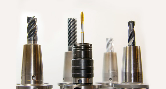
Chamfering is a critical step in CNC machining that involves creating beveled edges on parts to enhance functionality, aesthetics, and ease of assembly. To achieve the desired results, selecting the appropriate chamfering tool is crucial. Different types of tools offer various capabilities, and understanding the right parameters is key to ensuring high-quality machining results. Below, we’ll explore the types of chamfering tools and the key considerations for selecting the right one.

Choosing the Right Chamfering Tool
Selecting the right chamfering tool depends on the machining application, the material being used, and the specific requirements of the part being produced. Different tools are suited to different tasks, from simple chamfering to complex geometries that require specialized tools. A proper selection will improve tool life, reduce production time, and deliver high-quality results.
Types of Chamfering Tools
Chamfering Mills
Chamfering mills are commonly used for creating simple beveled edges on flat surfaces. These tools are designed to cut at a specific angle and are highly effective for generating consistent chamfers on parts with straightforward geometries.
Advantages:
Limitations:
End Mills
End mills are versatile tools used for a variety of cutting tasks, including chamfering. When used for chamfering, end mills are able to cut along both the X and Y axes, making them ideal for more complex parts with irregular geometries or multi-axis machining.
Advantages:
Limitations:
Specialized Chamfering Tools
Specialized chamfering tools are designed specifically for chamfering operations and are used for creating high-quality chamfers on both flat and complex parts. These tools include chamfer mills with specific features like integrated tool geometries or adjustable angles.
Advantages:
Limitations:
CNC Chamfering Tools for Lathes
CNC chamfering tools for lathes are specialized tools designed for lathe machining operations, where parts rotate and the tool moves in and out of the workpiece. These tools typically feature specific tool geometries suited for cutting angles on rotating parts, such as shafts or circular components.
Advantages:
Limitations:
Considerations for Tool Selection
When selecting the appropriate chamfering tool, several factors must be considered to optimize performance and achieve the desired results. These considerations ensure that the tool is well-suited to the material, geometry, and specific application needs.
Material Compatibility:
Chamfering Requirements:
Tool Geometry and Size:
Durability and Cost:
Conclusion
The right selection of CNC chamfering tools ensures that parts are manufactured efficiently, with precision and durability. Whether using chamfering mills, end mills, specialized tools, or CNC chamfering tools for lathes, it’s important to consider factors like material compatibility, required chamfer specifications, tool geometry, and overall cost-effectiveness. By carefully evaluating these elements, you can optimize your machining processes and ensure the highest quality chamfered edges on your parts.
Here is a table summarizing the CNC Chamfering Tools and Considerations for Tool Selection:
| Tool Type |
Description |
Advantages |
Limitations |
| Chamfering Mills |
Used for simple beveled edges on flat surfaces |
- Suitable for high-volume machining - Efficient for uniform chamfers |
- Limited to flat surfaces with a consistent angle |
| End Mills |
Versatile tools used for chamfering on various geometries |
- Can handle a variety of angles and shapes - Flexible and adaptable to multi-axis machining |
- More complex programming - Slower cutting speeds for high-volume production |
| Specialized Chamfering Tools |
Designed specifically for precise chamfering operations |
- High precision and superior surface finish - Handles complex geometries |
- Typically more expensive - Limited availability depending on CNC machine |
| CNC Chamfering Tools for Lathes |
Used for chamfering parts in lathe machining operations |
- Efficient for cylindrical or rotating parts - High precision chamfering on rotating components |
- Limited to lathe-based CNC machines - Requires additional setups for non-rotating parts |
| Consideration |
Details |
| Material Compatibility |
- Choose tools based on material hardness and composition |
| - Carbide tools for harder materials; HSS for softer materials | |
| Chamfering Requirements |
- Specify angle and size of chamfer for tool selection |
| - Tools should match precision and tolerance needs | |
| Tool Geometry and Size |
- Flute length, geometry, and diameter impact performance |
| - Longer flutes for deeper cuts; shorter flutes for rigidity | |
| Durability and Cost |
- Carbide tools last longer but cost more |
| - Cost-effective tools for softer materials or less complex tasks |
This table summarizes the key tools available for CNC chamfering and provides insight into the considerations for selecting the right tool.
Here’s a table summarizing the Key CNC Machining Parameters for Chamfering:
| Parameter |
Details |
Impact on Chamfering |
| Feed Rate |
The rate at which the tool advances through the material. | - Affects surface finish and chip removal rate |
| - Too high a feed rate may cause poor surface finish and increased tool wear | ||
| Cutting Forces |
The force required to shear material during cutting. | - High cutting forces may lead to tool deflection or vibration, affecting chamfer quality |
| - Lower forces help achieve better precision and longer tool life | ||
| Surface Finish |
The smoothness of the machined surface after chamfering. | - Controlled feed rate and spindle speed can help achieve desired surface finish |
| Tool Life |
The amount of time a tool can perform effectively before it needs replacement. | - Excessive cutting forces, feed rates, or improper parameters reduce tool life |
| Spindle Speed |
The rotational speed of the spindle and tool during machining. | - Affects cutting forces and surface finish |
| - High spindle speeds can improve surface finish but may lead to excessive wear | ||
| Material Hardness |
The resistance of the material to deformation or cutting. | - Harder materials require lower feed rates, specialized tools, and slower speeds |
| - Softer materials allow faster speeds and feed rates without compromising finish | ||
| Tool Materials |
The composition of the tool (e.g., carbide, high-speed steel). | - Harder materials (carbide, ceramics) provide longer tool life but higher costs |
| - Soft materials (HSS) are cheaper but wear faster on harder materials | ||
| Desired Surface Finish |
The finish quality required for the chamfered edges, ranging from rough to polished. | - Determines the necessary cutting parameters for tool selection, speed, and feed rate |
| Parameter |
Details |
Impact on Chamfering |
| Depth of Cut |
The distance the tool penetrates into the material. | - Affects the total material removal rate and finish quality |
| - Shallow depth of cut helps reduce tool stress and improve finish | ||
| Shallow Depth of Cut |
A smaller cut made in one pass. | - Helps achieve a finer finish but takes more passes to complete the chamfer |
| Incremental Cutting |
Making several passes to gradually remove material. | - Reduces the risk of excessive tool wear and damage to the material |
| - Essential for deep or high-precision chamfers |
This table provides an overview of how key CNC machining parameters influence chamfering operations and how they should be adjusted based on the material, tool, and desired results.
Chatter During Chamfering
Chatter refers to vibrations that occur during the machining process, leading to poor surface finish and reduced accuracy. These vibrations can be caused by improper tool selection, incorrect machining parameters, or machine instability.
To address these issues, several countermeasures are recommended:
Tool Selection
Increase Tool Rigidity
Reduce the Number of Blades
Reduce Spindle Speed
Reduce Chamfer Width
Uneven Chamfer Width
Uneven chamfer width can occur when there is inconsistency in the tool's position, wear, or programming errors. This can affect the precision and functionality of the chamfer, leading to quality issues in the final product.
Solution:
Consistent Programming and Setup
Tool Wear Management
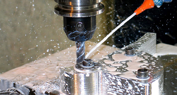
Chip Management During Machining
During chamfering, chips generated from material removal need to be managed effectively to ensure smooth machining operations and prevent damage to the tool or workpiece. Poor chip management can cause clogging, excessive heat buildup, and inconsistent cuts.
Solution:
Use Coolants/Lubricants
Optimize Feed Rate and Speed
Periodic Tool Cleaning
These strategies can effectively tackle the most common challenges encountered during chamfering processes, leading to improved machining accuracy, extended tool life, and better-quality chamfered edges.
Here’s a table summarizing the Common Chamfering Challenges and Solutions:
| Challenge |
Description |
Solution |
| Chatter During Chamfering | Vibrations caused by tool instability, leading to poor surface finish and inaccurate chamfers. | - Tool Selection: Use vibration-resistant tools. |
| - Increase Tool Rigidity: Use shorter, stiffer tools to minimize flex. | ||
| - Reduce the Number of Blades: Fewer blades reduce vibrations and improve surface quality. | ||
| - Reduce Spindle Speed: Lower speed to reduce vibrations, especially in harder materials. | ||
| - Reduce Chamfer Width: A smaller chamfer width reduces the tool load and vibration. | ||
| Uneven Chamfer Width | Inconsistency in chamfer width caused by programming errors, tool wear, or machine setup issues. | - Consistent Programming & Setup: Ensure accuracy in toolpath programming and machine calibration. |
| - Tool Wear Management: Replace or sharpen worn tools to maintain consistent chamfer width. | ||
| Chip Management During Machining | Inability to effectively clear chips can cause clogging, overheating, and inconsistent cuts. | - Use Coolants/Lubricants: Apply cooling fluids to remove chips and reduce heat. |
| - Optimize Feed Rate and Speed: Adjust feed rate and speed to control chip formation and clearance. | ||
| - Periodic Tool Cleaning: Regularly clean the tool to prevent chip buildup and reduce tool wear. |
This table highlights the key challenges in chamfering and offers practical solutions for each to ensure smooth and effective machining.
Overcutting or Undercutting
Problem:
Overcutting or undercutting refers to errors in the chamfer depth or angle that result in a chamfer that is either too deep or too shallow. This leads to poor fitment, aesthetics, and functionality of the part.
Cause:
Solution:
Uneven Chamfer Edge
Problem:
An uneven chamfer edge occurs when one side of the chamfer is more pronounced than the other, leading to inconsistency in the final part.
Cause:
Solution:
Excessive Tool Wear
Problem:
Excessive tool wear results in a loss of sharpness, reduced cutting performance, and an overall decline in chamfer quality, leading to poor surface finishes and increased machining time.
Cause:
Solution:
Programming Error
Problem:
Programming errors occur when the CNC code is incorrect, leading to unintended tool paths, incorrect chamfer angles, or undesired results in the final part.
Cause:
Solution:
These common mistakes can significantly impact the final output in CNC chamfering. By understanding the causes and applying the recommended solutions, manufacturers can reduce errors, improve part quality, and optimize machining efficiency.
Here’s a table summarizing Common Mistakes and Avoidance Methods in CNC Chamfering:
| Mistake |
Problem |
Cause |
Solution |
| Overcutting or Undercutting |
Chamfer depth or angle is incorrect, leading to poor fitment, aesthetics, and functionality. |
- Incorrect tool selection or wear - Inaccurate machine calibration - Improper programming - Incorrect feed rates |
- Proper tool selection - Verify toolpath - Calibrate and set up machines - Adjust feed rates and cutting parameters |
| Uneven Chamfer Edge |
One side of the chamfer is more pronounced than the other, causing inconsistency in the part. |
- Uneven tool wear - Tool deflection - Inconsistent feed rates - Machine instability |
- Regularly inspect and replace worn tools - Use stiffer, shorter tools - Adjust machine setup - Maintain a consistent feed rate |
| Excessive Tool Wear |
Tool loses sharpness, resulting in poor surface finishes and reduced cutting performance. |
- Aggressive cutting without considering material hardness - Using worn-out tools - Lack of cooling or lubrication - Incorrect cutting parameters |
- Choose the correct tool and replace it regularly - Use cooling fluids - Optimize feed rates and cutting speeds - Inspect tools regularly |
| Programming Error |
Incorrect CNC code leads to undesired tool paths and chamfer specifications. |
- Manual coding mistakes - Inadequate program verification - Miscommunication between design and machining teams |
- Verify and simulate CNC programs - Use CAM software for precision - Ensure clear communication between design and machining teams - Double-check CNC code |
This table provides a clear breakdown of common mistakes in CNC chamfering, their causes, and the solutions to avoid or correct them.
Chamfers and bevels are two commonly used edge treatments in CNC machining. While they might seem similar, they serve different purposes and are applied in various scenarios. Understanding the difference between the two can significantly impact both the functionality and aesthetics of a part. Below, we explore their definitions, tools and machining methods, internal features, and more to help you distinguish between the two.

Definition
| Feature |
Chamfer |
Bevel |
| Edge Type |
A chamfer is a straight-edge cut that removes the sharp corner or edge, typically at a 45° angle. | A bevel is a slanted edge, not necessarily at a 45° angle, often used to create a slope between two surfaces. |
| Shape |
A straight-line cut. | A sloped edge, typically angled differently from a chamfer. |
| Purpose |
To ease assembly, reduce stress concentrations, improve safety, and enhance appearance. | To create an angular transition between two surfaces, often to fit into a specific part geometry or aesthetic. |
Tools and Machining Methods
| Feature |
Chamfer |
Bevel |
| Common Tools |
- Chamfer mills - End mills - Specialized chamfer tools |
- Bevel mills - Angular cutters - End mills |
| Machining Process |
Chamfers are typically created by straight-line cuts along the edges using dedicated chamfering tools. |
Bevels are created by cutting along the edge at an angle, often with specific angles required for the intended design. |
| Programming Complexity |
Chamfering is simpler to program as it often uses standard 45° or other common angles. |
Bevels require more precise control over the angle, making them more complex to program, especially if the angle varies. |
Internal Features
| Feature |
Chamfer |
Bevel |
| Internal Edges |
Chamfers typically do not alter the internal edges of parts; they only remove the sharp exterior edges. | Bevels can modify both internal and external edges, depending on the angle and application. |
| Part Fitment |
Chamfers are often used to ensure easier assembly or to prevent damage when parts come in contact. | Bevels are commonly used for precise alignment or fitting parts together at specific angles, especially in weldments. |
Connotation
| Feature |
Chamfer |
Bevel |
| Use in Manufacturing |
Chamfers are often used in parts requiring smooth edge transitions for safety, assembly, or machining efficiency. | Bevels are used in parts where a sloped edge is necessary for fitting or aesthetic purposes. |
| Context in Design |
Chamfers have a utilitarian connotation, commonly found in parts that need functional edge treatments (e.g., reducing stress or improving assembly). | Bevels are seen more in parts that require specific angular transitions, often for aesthetic or design precision. |
Machining Costs
| Feature |
Chamfer |
Bevel |
| Cost of Machining | Chamfering is generally less costly as it requires less precision and simpler tools. | Bevel machining can be more expensive due to the need for more precise tools and programming to achieve specific angles. |
Machining Time
| Feature |
Chamfer |
Bevel |
| Time Efficiency | Chamfering typically takes less time, especially for standard angles such as 45°. | Beveling can take more time, especially when non-standard angles are required or if the part geometry is complex. |
Stress Concentration
| Feature |
Chamfer |
Bevel |
| Stress Relief | Chamfers help reduce stress concentrations by smoothing the sharp edge, which is particularly important in load-bearing applications. | Bevels also relieve stress but can be more effective when precise angles are required to distribute forces along the edges. |
Safety
| Feature |
Chamfer |
Bevel |
| Safety Impact | Chamfers improve safety by removing sharp edges, reducing the risk of injury during handling or assembly. | Bevels also improve safety, particularly in parts where sharp edges could cause damage during operation or handling. However, bevels are often more aesthetic than safety-oriented. |
Conclusion
Both processes offer their own set of advantages depending on the specific needs of the part and its application in the overall design.
In CNC machining, several techniques are employed to treat edges for various purposes like improving fit, safety, functionality, and aesthetics. Three common edge treatments that often get compared with chamfers are edge breaks, countersinks, and deburring. While all of these processes can alter the geometry of a part’s edges, they each serve distinct functions. Here’s a detailed comparison to clarify the differences:
Chamfer vs. Edge Break
| Feature |
Chamfer |
Edge Break |
| Definition |
A chamfer is a straight-edge cut, typically at a 45° angle, that removes sharp corners or edges. | An edge break involves removing a small radius from the edge, which softens sharp corners without creating an angle. |
| Purpose |
Primarily used to ease assembly, reduce stress concentrations, and improve safety. | Used to reduce the risk of injury from sharp edges and prevent damage during handling. |
| Edge Geometry |
Straight, angular cut at a specified angle. | Rounded or radiused edges, with no sharp corners. |
| Common Applications |
Assembly parts, mechanical components, or parts requiring smooth transitions. | Prevents injury and wear in parts that don’t require specific angle modifications. |
| Machining Complexity |
Relatively simple, often requiring specific chamfering tools. | Simple to apply with a radius tool, often with minimal programming complexity. |
| Benefits |
Improves part fit and assembly. Reduces sharpness for safety and stress relief. | Softens edges to reduce injury risk, improves part handling. |
| Drawbacks |
May not be appropriate for parts that require rounded edges or very specific angles. | Doesn't provide the same functional edge treatment as chamfers, such as improved stress distribution. |
Chamfer vs. Countersink
| Feature |
Chamfer |
Countersink |
| Definition |
A chamfer removes a sharp edge by creating an angled cut, typically 45°, between two surfaces. | A countersink creates a conical recess around a hole, usually to fit a specific type of screw head. |
| Purpose |
Used to create smoother edges for safety, ease of assembly, or aesthetic appeal. | Primarily used to accommodate countersunk screws, allowing them to sit flush with the part's surface. |
| Edge Geometry |
Straight, angular cut. |
Conical, typically 82° or 90° angle, depending on the screw. |
| Common Applications |
Structural parts, mechanical components, and parts requiring a smooth edge. | Assembly parts that require flush screw placement, commonly in aerospace, automotive, and electronics. |
| Machining Complexity |
Relatively easy to machine, with simple programming for standard angles. | More precise programming is required to ensure the correct depth and angle for the countersink. |
| Benefits |
Reduces stress, enhances safety, and facilitates smoother assembly. | Provides a flush seating for screws, preventing damage and allowing for a more secure fastener fit. |
| Drawbacks |
Not suitable for accommodating screws or fasteners. | Does not provide the same safety and stress-relieving benefits as a chamfer. |
Chamfer vs. Deburring
| Feature |
Chamfer |
Deburring |
| Definition |
A chamfer involves cutting away a corner at an angle to remove sharp edges or create a smooth transition. | Deburring is the process of removing unwanted material (burrs) from the edges of a part after machining. |
| Purpose |
Primarily for aesthetic appeal, functional assembly, and stress relief. | To eliminate burrs, sharp edges, and leftover material that could affect part function or safety. |
| Edge Geometry |
Angular, with specified angles. | Burrs are usually small, ragged, or sharp protrusions left after cutting, drilling, or machining. |
| Common Applications |
Parts requiring edge smoothness for assembly, aesthetics, or stress distribution. | Parts that need to meet strict functional or safety standards, such as medical or aerospace components. |
| Machining Complexity |
Simple to program for standard chamfer angles. | May require specialized deburring tools or manual processes for small, intricate parts. |
| Benefits |
Improves safety, assembly, and appearance while relieving stress. | Removes unwanted burrs, improving part performance, safety, and ensuring precise fits. |
| Drawbacks |
Not intended for removing burrs or rough edges that need to be smoothed out. | Does not add the functional benefits of a chamfer, such as edge transition or stress reduction. |
Conclusion
While chamfering, edge breaking, countersinking, and deburring all serve to modify the edges of a part, they are distinct processes with unique benefits and applications:
Choosing the right edge treatment depends on the part’s intended function, safety requirements, and aesthetic or assembly needs.
In CNC machining, the choice between fillet and chamfer largely depends on the specific needs of the part’s design, functionality, and performance. Both fillets and chamfers are used to treat the edges of a part, but they each serve different purposes and come with distinct advantages and disadvantages. Here are the key factors to consider when deciding between these two edge treatments:

1. Machining Time
| Fillet |
Chamfer |
| A fillet requires a radius to be applied, which may involve more complex tool paths, especially for larger radii or intricate geometries. This can result in longer machining times. | A chamfer, being an angular cut, is often simpler and faster to machine, particularly when the angles are consistent and the geometry is straightforward. |
| Machining Time: Generally higher due to complexity. | Machining Time: Lower due to simplicity. |
2. Cost
| Fillet | Chamfer |
| Fillets require precise radii cutting, and tool wear can be higher for larger radii or intricate parts. The need for more expensive tools may increase costs. | Chamfers are generally more cost-effective as they can be produced quickly with less wear on tools. They may require only a basic milling cutter or end mill. |
| Cost: Potentially higher due to tool wear and complexity. | Cost: Lower due to faster, simpler machining. |
3. Attractiveness
| Fillet |
Chamfer |
| Fillets are often used in aesthetic applications where a smooth, curved transition between two surfaces is desirable. The soft, flowing curve gives a polished look. | Chamfers provide a crisp, angular transition, offering a more industrial or technical look. This may be suitable for parts requiring a precise, sharp edge. |
| Attractiveness: Ideal for rounded, smooth edges in decorative or ergonomic applications. | Attractiveness: Provides a sharp, professional appearance for technical components. |
4. Rust and Corrosion Resistance
| Fillet |
Chamfer |
| Fillets may be more prone to accumulating moisture or contaminants in the radius, potentially leading to localized rust or corrosion over time, especially in certain environments. | Chamfers can be beneficial for corrosion resistance as the sharp edge allows for better cleaning and drying after exposure to moisture. They often provide a cleaner edge for coatings or finishes. |
| Rust Resistance: Potential issues in intricate, enclosed spaces. | Rust Resistance: Better for preventing moisture accumulation. |
5. Pressure and Stress Distribution
| Fillet |
Chamfer |
| Fillets are excellent at distributing stress and pressure evenly across the part, especially in areas subject to heavy loads or mechanical forces. The rounded shape minimizes localized stress concentrations. | Chamfers help reduce stress but are more effective for easing assembly and creating smoother transitions. They are often used in areas where pressure distribution is less critical. |
| Pressure & Stress: Ideal for load-bearing components where smooth stress distribution is required. | Pressure & Stress: Suitable for parts where stress relief is secondary to functionality. |
6. Hole Edges and Assembly
| Fillet |
Chamfer |
| Fillets can be challenging for parts with holes, as the rounded edge may interfere with the fit of fasteners or create difficulty in assembly. They are generally not used in holes. | Chamfers are often used around holes to allow for flush assembly of fasteners, screws, or other components. The angled edges help parts fit together more easily and are ideal for facilitating bolt or screw insertion. |
| Hole Edges: Not typically used for holes or fastener assembly. | Hole Edges: Commonly used to facilitate assembly and prevent issues with hole alignment. |
Conclusion
The decision to use a fillet or chamfer depends on the specific requirements of the part and its application. Here’s a summary of when to use each edge treatment:
By carefully considering these factors — machining time, cost, aesthetics, corrosion resistance, stress distribution, and assembly needs — you can determine which edge treatment best fits your CNC machining project.
Measuring the angle of a chamfer is a crucial step in ensuring that your CNC machining parts are produced to precise specifications. Several tools and methods can be used to accurately measure the chamfer angle. Below are the most common techniques and the pros and cons of each.
1. Bevel Protractor
A bevel protractor is a versatile tool used for measuring angles, including chamfer angles, with high accuracy. It consists of a blade that can be adjusted to different angles, and the protractor scale can provide precise angle measurements.
Advantages
Limitations
Best Suited for:
2. CMM (Coordinate Measuring Machine)
A Coordinate Measuring Machine (CMM) uses a probe to touch specific points on a part’s surface and measures the coordinates of those points. The machine can calculate the angle of the chamfer by analyzing the spatial relationship between the points on the chamfered surface.
Advantages
Limitations
Best Suited for:
3. Optical Comparator
An optical comparator projects the profile of a part onto a screen, allowing the operator to visually measure the angle of a chamfer. This tool magnifies the part and compares the chamfer angle to a predefined scale or template.
Advantages
Limitations
Best Suited for:
4. Chamfer Gauge
A chamfer gauge is a specialized tool used for measuring chamfer angles. It typically has a series of preset angle blocks or a rotating dial that allows users to compare the chamfer’s angle to known values.
Advantages
Limitations
Best Suited for:
Conclusion
Each method for measuring the angle of a chamfer has its pros and cons, depending on the accuracy required and the type of machining environment. For high-precision parts and large production runs, a CMM or optical comparator may be the best option. For quick checks or smaller batches, a bevel protractor or chamfer gauge might be more suitable. The key is selecting the method that balances accuracy, efficiency, and cost based on your specific machining needs.
Here's a table summarizing the different methods for measuring the angle of a chamfer:
| Measurement Method |
Advantages |
Limitations |
Best Suited For |
| Bevel Protractor |
- Accurate for small chamfers - Easy to use - Manual control |
- Limited range for large angles - Skill-dependent |
- Small chamfers - Quick, in-field measurements |
| CMM (Coordinate Measuring Machine) |
- High accuracy (micrometers) - Non-destructive - Automated |
- Expensive - Requires specialized knowledge |
- High-precision environments - Complex geometries - Quality control labs |
| Optical Comparator |
- Visual feedback - Non-contact - Fast measurement |
- Limited precision - Needs regular calibration |
- Quick inspection - Parts that can be visually compared |
| Chamfer Gauge |
- Simple to use - Portable - Affordable |
- Less accurate than CMM - Limited angle range |
- Routine checks - On-the-go measurements - Simple chamfers |
This table should give a clear overview of the pros, cons, and ideal applications of each method.
As the demand for precision and speed in CNC machining increases, several advanced solutions have emerged to optimize chamfering processes. These innovations help manufacturers achieve more consistent results, reduce cycle times, and minimize tool wear, ultimately increasing efficiency and lowering costs. Here are some key innovations in chamfering:
1. CAM-Driven Automation
CAM (Computer-Aided Manufacturing) systems are revolutionizing the way chamfering is performed in CNC machining. By integrating automatic tool path generation and tool control into the software, CAM-driven systems allow for seamless programming and more precise chamfering operations. These systems can optimize the tool's movement based on the part’s geometry, reducing human error and programming time.
Benefits:
Applications:
2. Indexable Chamfer Milling Cutters
Indexable chamfer milling cutters offer great flexibility in chamfering operations. These tools use replaceable inserts that can be rotated to offer fresh cutting edges, extending the tool’s life and reducing the cost of consumables. The design allows for quicker changes, enabling manufacturers to switch between different chamfering angles and sizes with ease.
Benefits:
Applications:
3. Multi-Axis Chamfering
Multi-axis CNC machines offer the ability to perform chamfering on parts with complex geometries, including curved or angled surfaces that traditional machines cannot handle. These machines can manipulate the tool in multiple directions, allowing for chamfering of challenging features like inclined or spherical edges. Multi-axis systems are ideal for precision parts that require tight tolerances.
Benefits:
Applications:
4. High-Feed Chamfering Tools
High-feed chamfering tools are designed to perform chamfering operations at significantly higher speeds and feeds than traditional tools. These tools are optimized to remove material rapidly while maintaining high-quality finishes. They are ideal for high-volume manufacturing environments, where reducing cycle time is crucial for maintaining profitability.
Benefits:
Applications:
5. Adaptive Machining Systems
Adaptive machining systems use real-time data to adjust machining parameters based on feedback from sensors or monitoring systems. This can include adjustments to cutting speed, tool position, or feed rates during the chamfering operation. Such systems ensure that the chamfering process remains consistent despite changes in part geometry or material variations.
Benefits:
Applications:
These innovations make chamfering more efficient, cost-effective, and adaptable to a wide range of machining needs. By leveraging these technologies, manufacturers can enhance their productivity while ensuring the precision and quality of their chamfering operations.
Here’s a table summarizing the innovative solutions for efficient chamfering:
| Innovation |
Benefits |
Applications |
| CAM-Driven Automation |
- Increases programming speed and accuracy - Reduces human intervention - Adapts to complex geometries |
- Complex or high-volume machining - Parts requiring multiple machining steps |
| Indexable Chamfer Milling Cutters |
- Reduced tool replacement time - Increased tool life with replaceable inserts - Versatile for different chamfer sizes and angles |
- High-volume production - Parts with varying chamfer sizes and angles |
| Multi-Axis Chamfering |
- Works on complex, multi-dimensional surfaces - Higher accuracy - Improved surface finishes |
- Aerospace and automotive parts - Components with non-linear surfaces |
| High-Feed Chamfering Tools |
- Increased material removal rates - Improved efficiency - Better tool life with reduced wear |
- Mass production runs - Parts with high material removal requirements |
| Adaptive Machining Systems |
- Real-time adjustments for optimized machining - Consistent results in varying conditions - Reduced scrap and rework |
- Parts with variable material hardness - High-tolerance, quality-sensitive components |
This table highlights the key benefits and best applications for each of the innovative chamfering solutions.
Chamfering plays a vital role in CNC machining, offering numerous benefits, including improved safety, enhanced aesthetics, and the reduction of stress concentrations. By carefully selecting the right chamfering method, tools, and parameters, manufacturers can achieve high-quality results while optimizing efficiency and cost-effectiveness. Understanding the various chamfer types, machining methods, and challenges helps ensure that chamfering processes are performed with precision and consistency.
As technology continues to evolve, innovative solutions such as CAM-driven automation, multi-axis chamfering, and high-feed chamfering tools are revolutionizing the way chamfers are created, enabling manufacturers to tackle complex geometries with ease and improve overall machining productivity. Whether you are working on mechanical parts, aerospace components, or consumer electronics, chamfering is an essential technique that contributes significantly to the functionality, safety, and appearance of CNC machined products.
By considering the factors discussed in this article and adopting best practices, businesses can refine their chamfering processes, reduce common mistakes, and avoid challenges such as tool wear and uneven chamfer widths, ultimately ensuring that their CNC machining operations remain competitive and efficient.

1. What role does chamfering play in manufacturing?
Chamfering in manufacturing helps improve part functionality by reducing stress concentrations, facilitating assembly, and enhancing safety. It also improves aesthetics and ensures a better fit for parts that need to interlock or be joined.
2. What is the most common angle for chamfering?
The most common chamfer angle is typically 45 degrees, but it can vary depending on the part design, machining requirements, and the desired functionality of the chamfer.
3. Is chamfering the same as deburring?
No, chamfering and deburring are different processes. Chamfering refers to cutting a beveled edge on a part, typically to remove sharp edges, while deburring removes unwanted material or burrs from the surface after machining.
4. What is the difference between chamfering and beveling?
Chamfering and beveling both involve cutting the edges of a part, but chamfering is generally a flat cut that creates a specific angle (usually 45 degrees), while beveling can be a more complex, angular cut that may not necessarily be flat.
5. When should chamfering be avoided?
Chamfering should be avoided when the part requires load-bearing contact edges with close verticality, when a flush seal or gasket surface is needed, when there are aesthetic or geometric design restrictions, or if the material thickness is insufficient.
6. How is chamfering used in CAD software?
In CAD software, chamfering is used to apply a beveled edge to corners or intersections in part designs. The angle and distance can be defined, and the software automatically adjusts the geometry.
7. How can chamfers be measured accurately?
Chamfers can be measured using tools like bevel protractors, coordinate measuring machines (CMM), optical comparators, and chamfer gauges, which allow precise measurement of the angle and dimensions.
8. Can chamfers be added automatically during CNC machining?
Yes, chamfers can be added automatically during CNC machining using specific tool paths or by programming the CNC machine to incorporate chamfering at relevant edges during the machining process.
9. What tools are best for creating chamfers?
Tools like chamfering mills, end mills, specialized chamfering tools, and CNC lathe tools are commonly used for creating chamfers, with the choice depending on the part geometry and required precision.
10. Does chamfering affect structural strength?
Chamfering generally has minimal impact on the structural strength of a part. In some cases, it can reduce stress concentrations, improving the part's overall durability. However, chamfering too much can weaken the edge.
11. What types of chamfers can be made with CNC machining?
CNC machining can produce various types of chamfers, including leg length chamfers, distance and angle chamfers, double distance (asymmetric) chamfers, hole entry chamfers, and custom chamfer profiles.
12. What tools are commonly used for CNC chamfering?
Common tools for CNC chamfering include chamfer mills, end mills, indexable cutting tools, and specialized chamfering inserts that are designed for specific part requirements and angles.
13. What are the key machining parameters for chamfering?
Key parameters for chamfering include feed rate, spindle speed, depth of cut, tool life, cutting forces, and the surface finish. These parameters help achieve consistent chamfer quality.
14. How can you ensure consistent chamfer quality?
To ensure consistent chamfer quality, it's important to maintain proper machine settings, use the correct tool geometry, monitor feed rates, and regularly inspect tool wear. Calibration of the machine also plays a key role in precision.
15. What is chamfering in CNC?
Chamfering in CNC machining is the process of removing sharp edges from a part by cutting a beveled edge at a specific angle. It’s often done to improve assembly, safety, and aesthetics.
16. What is the purpose of chamfering?
The purpose of chamfering is to remove sharp edges from parts, reduce stress concentrations, improve fit and assembly, and provide a more professional and aesthetically pleasing appearance.
17. What is the difference between CNC fillet and chamfering?
A fillet is a rounded edge, while a chamfer is a straight, beveled edge. Fillets are used to reduce stress in certain applications, while chamfers are more often used to improve fit, safety, and appearance.
18. What is the process of chamfering?
Chamfering involves using a cutting tool to bevel the edges of a part at a specified angle. This can be done manually or automatically using a CNC machine, depending on the complexity and precision required.
19. How to calculate chamfers?
Chamfers can be calculated by measuring the distance from the corner to the beginning of the chamfer and the angle of the cut. The angle is typically 45 degrees, but it can vary based on the design.
20. What are the benefits of chamfering?
The benefits of chamfering include improved safety by removing sharp edges, enhanced aesthetics, better part fit, reduced stress concentrations, and easier assembly and handling.
21. What are the disadvantages of chamfering?
Disadvantages of chamfering include potential weakening of parts if done excessively, increased machining time if high precision is required, and higher tool wear.
22. What is chamfering in CAD?
Chamfering in CAD refers to the application of a beveled edge to a corner or part intersection, typically defined by a specific angle and distance to meet design and manufacturing requirements.
23. How to dimension chamfers?
Chamfers are typically dimensioned by specifying the distance from the corner to the start of the chamfer and the angle of the chamfer. CAD tools can help in setting these dimensions accurately.

 +86 15099911516


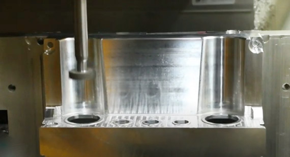
 Read more