16 years one-stop China custom CNC machining parts factory

Hey there I’m VMT Sam!
With 25 years of CNC machining experience we are committed to helping clients overcome 10000 complex part-processing challenges all to contribute to a better life through intelligent manufacturing. Contact us now
 196 |
Published by VMT at Aug 18 2026 | Reading Time:About 5 minutes
196 |
Published by VMT at Aug 18 2026 | Reading Time:About 5 minutes


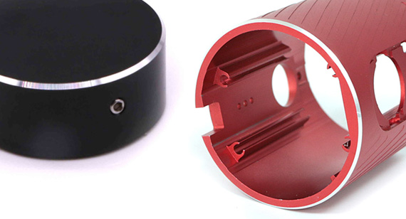
A bright edge can make an aluminum part look premium, but it also makes small machining problems much easier to see. Tool wear, vibration, poor datum control, cutting-fluid residue, burrs, or improper handling can turn an otherwise accurate CNC part into a cosmetic reject. The key is to diagnose the real cause instead of repeatedly adjusting one machining parameter.
Common high-gloss CNC machining defects in aluminum parts include horizontal tool lines, vertical chatter marks, entry and exit marks, uneven bright-edge width, white spots, burrs, and scratches. Preventing them requires control of the cutting tool, spindle, fixture, finishing allowance, toolpath, cleaning, inspection, and post-machining handling.
This guide focuses specifically on the defects you can see on high-gloss aluminum surfaces, why they happen, and how to reduce them from prototype through batch production.

High-gloss machining is often used to create localized decorative features rather than finishing the entire part.
Common high-gloss features on custom aluminum machined parts include:
These surfaces are normally created by a controlled finishing cut after the main geometry has already been machined.
Because the surface is highly reflective, very small variations that may be acceptable on a normal CNC-machined surface can become visually obvious.
A minor tool mark, small amount of runout, slight change in edge width, or scratch may have little effect on function but still cause cosmetic rejection.
If you need a broader explanation of the process, cutting tools, materials, and surface-finishing sequence, see our CNC high-gloss machining guide.
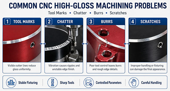
Most high-gloss defects are not caused by one factor alone.
The visible problem is often the result of several manufacturing variables interacting with each other.
For example, a chatter mark may involve:
fixture rigidity + tool overhang + spindle condition + finishing allowance + feed strategy
rather than one incorrect cutting parameter.
The most important factors usually include:
This is why simply increasing spindle speed or reducing feed does not always solve the problem.
The defect should first be identified by its appearance and location, then traced back through the machining process.
| Defect | Common Causes | Main Control Direction |
| Horizontal tool lines | Tool wear, micro-chipping, runout, built-up material | Inspect tool and spindle before changing parameters |
| Vertical chatter marks | Vibration, weak fixture, excessive cutting load | Improve rigidity and stabilize the finishing cut |
| Entry and exit marks | Poor toolpath transition, unstable engagement | Optimize entry, exit, overlap, and cutting direction |
| Uneven bright-edge width | Datum error, flatness, distortion, fixture variation | Control geometry before the final bright cut |
| White spots or staining | Fluid residue, contamination, delayed cleaning | Improve cleaning and process transfer |
| Burrs | Dull tool, cutting direction, edge geometry | Prevent burr formation during machining |
| Scratches | Chips, handling, inspection, packaging | Protect the surface after machining |
The sections below explain each problem in more detail.
1. Horizontal Tool Lines on High-Gloss Aluminum Surfaces
Horizontal lines are one of the most noticeable defects on bright aluminum edges and reflective surfaces.
They may appear as repeated straight marks across a chamfer, ring, or flat decorative area.
What Causes Horizontal Tool Lines?
Common causes include:
A very small defect on a finishing tool can be transferred directly onto the reflective surface.
This creates an important difference between normal CNC machining and high-gloss machining:
a tool may still hold dimensional tolerance while already producing unacceptable cosmetic surfaces.
How Can Horizontal Tool Lines Be Prevented?
Start by checking the cutting tool before changing the machining program.
The review should include:
If the defect repeats at a regular interval, the tool and spindle system deserve particular attention.
For batch production, do not wait until the tool completely fails.
Tool life should also be controlled according to cosmetic quality.
Tip: If the first parts in a batch look clean but the lines gradually become more visible, tool wear should be investigated before changing multiple machining parameters.
2. Vertical Lines and Chatter Marks
Vertical lines or periodic waves usually indicate instability somewhere between the machine, cutting tool, fixture, and workpiece.
These marks are especially visible when light moves across a bright chamfer or reflective face.
What Causes Chatter on High-Gloss Surfaces?
Possible causes include:
A thin aluminum housing can be particularly sensitive.
The same fixture may appear stable during rough machining but allow enough movement during the final finishing pass to create visible chatter.
How Can Chatter Marks Be Reduced?
The machining system should be reviewed as a whole.
Check:
Reducing feed may sometimes help, but it should not become the automatic solution.
If the fixture is unstable, simply reducing feed may increase cycle time without eliminating the root cause.
Note: The visible chatter mark is the symptom. The real problem may be fixture rigidity, spindle condition, part deformation, or cutting load.
3. Entry and Exit Tool Marks
A high-gloss surface can look perfect through most of the cutting path but still show a visible line where the tool enters or exits.
This is particularly common on:
Why Do Entry and Exit Marks Appear?
Possible causes include:
A toolpath that is acceptable for a hidden functional surface may not be suitable for a decorative feature.
How Should the Toolpath Be Improved?
The entry and exit location should be selected according to the cosmetic surface.
Depending on the geometry, the machining strategy may use:
The goal is not simply to make the shortest CNC program.
For appearance-critical machining, a slightly longer but smoother toolpath can reduce visible transitions and rework.
This is one area where the machining strategy should be developed around the final appearance rather than cycle time alone.
4. Uneven Bright-Edge Width
An uneven bright edge is a common problem on anodized housings, knobs, camera parts, decorative panels, and other aluminum components.
The bright chamfer may appear wider on one side and narrower on another even though the cutter follows the programmed path correctly.
Why Does Bright-Edge Width Become Uneven?
Possible causes include:
The high-gloss operation may reveal a dimensional problem created much earlier in the manufacturing process.
For example, consider a circular control knob with:
If the final assembly is located by the center bore, the bright ring may need to be concentric with the bore rather than simply follow the outside diameter.
If the wrong datum controls the decorative feature, the dimensions may still individually pass inspection while the finished part looks off-center.
How Can Bright-Edge Width Be Controlled?
The bright-edge requirement should be connected to the functional datum during DFM review.
Before the final high-gloss operation, control:
This is especially important for aluminum CNC machining parts that combine appearance-critical edges with bores, mating surfaces, thin walls, or tight assembly requirements.
5. White Spots and Surface Staining
White spots or cloudy areas can appear on a high-gloss aluminum surface even when the machining itself was initially acceptable.
These defects are particularly frustrating because they may appear during cleaning or after the part has been sitting between production processes.
What Causes White Spots on High-Gloss Aluminum?
Possible causes include:
Freshly machined aluminum surfaces can be sensitive to contamination and surface reactions.
A high-gloss finish also makes local appearance changes easier to see.
How Can White Spots Be Reduced?
Cleaning should be treated as part of the manufacturing process rather than a simple housekeeping step.
Control:
Parts should not be left unnecessarily with cutting fluid or contamination on the finished cosmetic surface.
If high-gloss machining is followed by anodizing or another surface finishing process, the transfer conditions between the two operations should also be defined.
Tip: When white spots appear only after storage rather than immediately after machining, investigate cleaning, moisture, contamination, and packaging conditions before changing the cutting program.
6. Burrs on Bright Aluminum Edges
A small burr can make a precision-machined bright edge look unfinished.
It can also create:
What Causes Burrs?
Common causes include:
Why Is Aggressive Manual Deburring Risky?
For a conventional machined edge, a technician may be able to remove a burr manually without affecting appearance.
On a reflective high-gloss edge, aggressive hand deburring may create:
This means burr control should begin during machining.
How Can Burrs Be Prevented?
The machining plan should consider:
The goal is to minimize burr formation so that only light and controlled secondary treatment is required.
7. Scratches After High-Gloss Machining
A part can leave the CNC machine with an excellent surface and still become a cosmetic reject before shipping.
Scratches often occur after machining rather than during machining.
Where Do Scratches Usually Occur?
Common risk stages include:
High-gloss surfaces reflect light strongly, so even fine scratches can become visible.
How Can Scratches Be Prevented?
Appearance-critical parts should have a defined handling method.
Depending on the part, this may include:
Protective packaging should be considered part of the manufacturing plan, not something decided only after production is finished.
A perfect CNC surface has no value if it is damaged before it reaches your assembly line.
When a defect appears, changing several parameters at the same time makes diagnosis more difficult.
A more structured approach is to trace the defect through the manufacturing system.
Step 1: Identify the Defect Pattern
Ask:
The appearance can provide useful clues.
Step 2: Check the Cutting Tool
Inspect:
If the defect repeats at a regular spacing, the tool or spindle system may be involved.
Step 3: Check the Machine and Spindle
Review:
A surface-quality problem should not automatically be blamed on the CNC program.
Step 4: Check the Fixture
Look for:
Fixture behavior can affect both dimensional accuracy and cosmetic quality.
Step 5: Review the Finishing Allowance
High-gloss finishing should remove a controlled amount of material.
Excessive finishing stock increases cutting load.
Insufficient stock may leave:
The allowance should be established for the actual part, material, and tool.
Step 6: Review the Toolpath
Check:
A stable finishing path may reduce defects even when the tool and parameters remain unchanged.
Step 7: Review Cleaning and Handling
If the part looks good immediately after machining but develops spots or scratches later, check:
The defect may no longer be a CNC cutting problem.
There is no single feed rate, spindle speed, or finishing allowance that can be applied to every aluminum high-gloss machining project.
The appropriate cutting strategy depends on:
A narrow bright edge on a small control knob and a wide decorative surface on an electronic housing can require very different machining conditions.
This is why troubleshooting should focus on the relationship between the defect and the manufacturing system, rather than searching for one universal parameter.
Note: If reducing feed appears to improve the surface, that does not necessarily prove the original feed rate was the root cause. The slower cut may simply reduce the effect of an unstable fixture, worn tool, or excessive machining allowance.
For appearance-critical parts, controlling defects begins before the finishing tool touches the surface.
The drawing, datums, fixture, machining sequence, high-gloss feature, anodizing requirement, and inspection method need to work together.
DFM Review
The engineering review identifies:
This helps avoid situations where a part meets isolated dimensions but the high-gloss feature still appears uneven after assembly.
Fixture Optimization
High-gloss surfaces are sensitive to vibration and deformation.
Fixture design may need to provide additional support around:
If the part has already been anodized, fixture contact areas also need to protect the finished surfaces.
Machining Sequence Control
The relationship between:
rough machining → dimensional finishing → surface finishing → high-gloss cutting → final inspection
can affect both appearance and dimensional stability.
The sequence should therefore be selected according to the required final condition of the part.
Tool and Toolpath Control
For appearance-critical finishing, the tool condition and toolpath are reviewed for:
A more stable toolpath can be preferable even when it requires a slightly longer machining cycle.
In-Process Inspection
Critical geometry can be verified before the final bright-edge operation.
This is especially important when the appearance depends on:
If these relationships are already incorrect, high-gloss machining will only make the variation more visible.
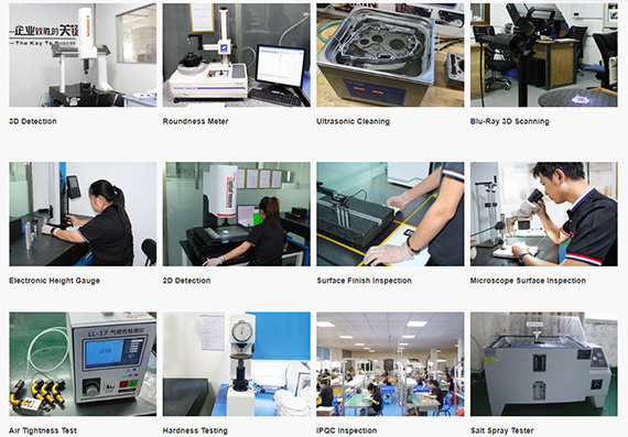
High-gloss parts need both dimensional and cosmetic inspection.
Dimensional Inspection
Depending on the drawing, inspection may include:
Suitable measurement methods may include:
The method should match the actual tolerance and feature geometry.
Cosmetic Inspection
Visual inspection should evaluate:
Controlled lighting can help improve consistency.
For strict cosmetic requirements, an approved sample can also make the acceptance criteria clearer.
Terms such as:
can otherwise be interpreted differently by engineering, purchasing, machining, and quality teams.
Project Background
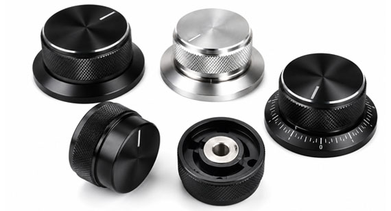
A customer required a black anodized aluminum control component with a narrow exposed bright edge around the front surface.
The bright feature was an important part of the product appearance.
Project Challenge
During prototype evaluation, the bright edge appeared slightly wider in some areas.
The individual dimensions were close to the drawing requirements, but the visual inconsistency was still noticeable because of the strong contrast between the black anodized body and exposed aluminum.
Root Cause Review
The problem could not be evaluated only from the final bright-edge program.
The review included:
The cosmetic feature needed to be controlled from the geometry that determined how the part would actually appear after assembly.
VMT Solution
The datum relationship and fixture strategy were adjusted before the final finishing operation.
The process also controlled:
The revised prototype was then used as the visual reference for production.
Result
The approved sample established a clearer standard for bright-edge width and overall appearance, helping reduce subjective differences during batch inspection.
How to Prevent High-Gloss Defects From Prototype to Batch Production
A successful prototype does not automatically guarantee consistent production.
Batch quantities introduce additional variables such as:
A controlled process may follow:
Drawing Review → DFM Feedback → Prototype Machining → High-Gloss Validation → Surface-Finish Validation → Dimensional Inspection → Cosmetic Approval → Batch Production → Final Inspection → Protective Packaging
The prototype should establish more than whether the part can be manufactured.
It should also confirm:
This provides a clearer reference before larger production quantities begin.
High-gloss defects are easier and less expensive to prevent during process planning than to repair after machining, anodizing, and cosmetic inspection are complete.
If your aluminum part includes:
the machining plan should connect the cosmetic requirement with the functional datums, fixture design, finishing allowance, toolpath, surface-finishing sequence, and inspection standard.
VMT can review your 2D drawing and 3D model to identify potential risks before production and provide DFM feedback for prototype and batch manufacturing.
Upload your drawings and request a quote if you need help controlling high-gloss surface defects on custom aluminum machined parts.
Send your 2D drawings, 3D CAD models, material, tolerances, high-gloss features, anodizing requirements, cosmetic surfaces and inspection requirements. VMT will review the manufacturing risks and provide DFM feedback and a custom quote.
All information and uploaded files are secure and confidential.
1 Tell us what you need
2 Get DFM & quote
3 Approve production
Email: inquiry@vimetal.com.cn
Why do horizontal lines appear on high-gloss aluminum parts?
Horizontal lines may result from tool wear, micro-chipping, built-up material, runout, or unstable cutting engagement. The cutting edge and spindle system should be checked before changing multiple machining parameters.
What causes vertical chatter marks on bright aluminum edges?
Common causes include vibration, fixture instability, thin-wall movement, excessive finishing allowance, tool overhang, spindle runout, or unstable cutting load.
Why does a high-gloss edge become wider on one side?
Uneven bright-edge width can result from poor flatness, part distortion, fixture positioning, incorrect datum selection, or uneven machining allowance from previous operations.
Why do white spots appear on high-gloss aluminum?
White spots or cloudy areas may be related to cutting-fluid residue, contamination, cleaning conditions, moisture, storage, or delays between machining and cleaning.
How do you prevent entry and exit marks?
Tool entry and exit should be placed away from critical visible regions when geometry allows. Arc transitions, controlled overlap, continuous finishing paths, and stable cutting engagement can help reduce visible marks.
Can slower feed eliminate high-gloss tool marks?
Sometimes it can improve the result, but it does not prove feed rate is the root cause. Tool wear, spindle runout, weak fixturing, or excessive finishing allowance may still be responsible.
Why are burrs difficult to remove from bright edges?
Manual deburring can scratch the reflective surface, round the edge, or change the chamfer width. It is usually better to reduce burr formation during machining.
Can scratches appear after CNC machining is complete?
Yes. High-gloss surfaces can be damaged during unloading, cleaning, inspection, surface finishing, assembly, packaging, or transport.
Does low surface roughness guarantee a good high-gloss finish?
No. Surface roughness is only one part of appearance. Tool patterns, waviness, chatter, scratches, edge width, and reflection consistency also affect visual quality.
Should high-gloss aluminum parts be inspected under controlled lighting?
Controlled lighting can make cosmetic inspection more consistent, especially when scratches, tool lines, stains, and reflection differences are important acceptance criteria.
Is an approved cosmetic sample useful?
Yes. A physical approved sample can help define acceptable bright-edge width, reflection, tool marks, anodizing transition, and overall appearance more clearly than general written descriptions.
Should high-gloss parts be prototyped before mass production?
Prototype validation is recommended when the project combines tight dimensions, anodizing, high-gloss machining, thin walls, critical datum relationships, or strict cosmetic requirements.


 +86 15099911516




 Read more