16 years one-stop China custom CNC machining parts factory

Hey there I’m VMT Sam!
With 25 years of CNC machining experience we are committed to helping clients overcome 10000 complex part-processing challenges all to contribute to a better life through intelligent manufacturing. Contact us now
 8055 |
Published by VMT at Feb 14 2025 | Reading Time:About 5 minutes
8055 |
Published by VMT at Feb 14 2025 | Reading Time:About 5 minutes


When it comes to manufacturing, the surface roughness of CNC machined parts plays a critical role in the performance and functionality of the final product. However, achieving the right surface finish can be tricky. For engineers and machinists, understanding how to measure and control surface roughness is essential. The surface roughness chart is a valuable tool in this process, providing a clear reference to determine the ideal finish for various applications. But why is it so important? How can a rough or smooth surface impact your project’s performance? Let’s explore the nuances of surface roughness and why getting it right is a key part of the engineering process.
A surface roughness chart is an essential reference in CNC machining that helps engineers measure and control the texture of machined surfaces. By understanding terms like Ra, Rz, and RMS, machinists can achieve the desired surface finish to enhance product performance, aesthetics, and function. This chart ensures consistency and precision in your CNC machining services and helps to choose the correct surface roughness for specific manufacturing needs.
Now that we have an overview of surface roughness and its importance, let’s dive deeper into the different measurement methods, chart symbols, and factors that influence surface finish. By understanding these components, you can better grasp how to optimize the manufacturing process for the best results.
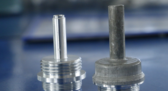
In manufacturing, surface finish refers to the texture of the surface left after machining or manufacturing processes. It is crucial because it affects not only the appearance of the part but also its functionality, durability, and performance in its intended application. A surface with a higher roughness value might have more friction, which can lead to wear or thermal buildup, whereas smoother finishes can enhance lubricity and resistance to corrosion.
For CNC machining parts, the right surface finish ensures that components fit together seamlessly, minimizing the risk of failure. It also has a significant effect on the part's fatigue resistance, as smoother surfaces are less prone to cracking under stress. Therefore, achieving the desired surface finish is essential for ensuring high-quality results.

The surface roughness of CNC machined parts refers to the microscopic texture or irregularities left on the surface during the machining process. This roughness can vary depending on factors like the material used, the cutting tools, and the machining method. The roughness profile is often quantified using values like Ra (Average Roughness), which measures the average deviations from a mean line, and Rz (Maximum Height of the Profile), which measures the highest point to the lowest point on a surface.
For precision parts where smoothness is critical—such as aerospace components or medical devices—understanding surface roughness is vital. With a precise surface finish, you can ensure parts meet quality standards, fit specifications, and provide optimal performance.
Surface finish plays a crucial role in determining the quality, longevity, and performance of a machined part. In some applications, a rough surface may be desirable for specific purposes, such as improving friction or wear resistance. However, in most cases, a smoother finish is preferred for reducing wear, improving strength, and ensuring the functionality of the part.
In the context of CNC prototype machining and custom CNC machining, achieving the correct surface finish is a vital aspect of turning prototypes into final products. By using the right techniques and knowing the required roughness values for each project, engineers can create parts that meet not only aesthetic but also mechanical and functional standards. Understanding surface finish also helps prevent defects like corrosion or part failure in the field, leading to longer service life and reliability.
The right surface finish can significantly enhance the performance of a product. For example, a smooth finish can improve the efficiency of mechanical parts by reducing friction, enhancing wear resistance, and making it easier to clean or seal the components. Additionally, an optimal surface finish is often required for parts that are meant to be painted, coated, or welded, as the surface's smoothness impacts adhesion and bonding.
For CNC machining, understanding the specific surface finish requirements is necessary to determine the right cutting tools and techniques. Whether it’s for custom CNC machining or mass production, the correct finish will lead to improved overall product quality, functionality, and aesthetic appeal.
Measuring surface roughness involves evaluating the texture of a surface to quantify its roughness. There are several methods for measuring surface roughness, with the most common ones being:
Each method has its advantages, with some being better suited for specific materials or surface finishes. Choosing the right measurement method is critical in obtaining accurate and reliable results.

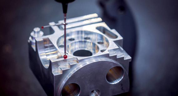
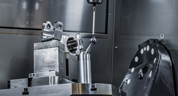
When it comes to evaluating the quality and texture of a CNC machined surface, selecting the appropriate method for measuring surface roughness is crucial. Each method provides valuable insights into the surface profile, helping engineers and machinists ensure that the finished product meets the required specifications. Depending on the material, the size of the part, and the precision needed, different techniques can be employed. Here, we’ll explore the most common methods for measuring surface roughness and how they can be applied in the manufacturing process.
Profiling Techniques
Profiling techniques are one of the most traditional and widely used methods for measuring surface roughness. These methods typically involve the use of a stylus probe, which moves across the surface of the material. As the stylus contacts the surface, it traces the profile and measures the variations in height, typically recording values like Ra (Average Roughness) and Rz (Maximum Height of Profile).
Profiling can be performed with both contact and non-contact techniques, though the contact method is the more traditional approach. These techniques can provide a detailed, continuous profile of the surface, making it easy to visualize and quantify roughness across the material. Profiling is highly effective for surfaces with defined textures, such as machined or ground parts, and it offers high accuracy for measuring small-scale roughness.
Area Techniques
Area techniques take a broader approach to measuring surface roughness by analyzing the surface texture over a larger area rather than just along a single line. This method typically involves scanning an area of the surface and capturing data that reflects the overall texture. Surface scanners and optical profilometers are often used to perform area-based measurements.
This method is particularly useful when assessing more complex surfaces with varying textures or for applications where the overall distribution of roughness across a part is important. Unlike traditional profilometers, area-based methods can provide a 3D map of the surface, giving engineers a clearer picture of surface uniformity and characteristics. This technique is beneficial in quality control when measuring parts with intricate designs or when an overall view of the surface profile is needed.
Microscopy Techniques
Microscopy techniques use advanced imaging methods, such as scanning electron microscopy (SEM) or optical microscopy, to examine the surface at a microscopic level. These methods allow for the detection of fine surface features, such as cracks, pits, and micro-textures, that might not be visible to the naked eye or through traditional measurement methods.
In the context of surface roughness measurement, microscopy techniques are valuable for parts that require ultra-fine measurements or when defects on the micro-scale need to be identified. For example, SEM can magnify a surface up to thousands of times, allowing for the measurement of roughness at extremely small scales, which is ideal for precision components used in industries like aerospace, medical, or electronics.

Inductive Methods
Inductive methods use electromagnetic induction to measure surface roughness by detecting changes in the inductance as a sensor moves over the surface. These methods are non-contact and are particularly beneficial for measuring roughness without physically touching the part. Inductive techniques can be highly accurate and are often used for parts made from conductive materials, such as metals, where the measurement is based on the change in the magnetic field caused by surface irregularities.
While inductive methods can be used for a wide range of materials, they are best suited for applications requiring continuous measurement or real-time monitoring during the machining process. These methods can quickly provide data on surface roughness, making them ideal for in-process quality control and large-scale production environments.
Machine Methods
Machine methods involve the use of in-process measurement tools integrated into CNC machines or other automated machinery. These tools assess surface roughness in real time during machining, allowing for immediate feedback on the quality of the surface being produced. The benefits of machine methods include the ability to adjust cutting parameters on the fly to achieve the desired surface finish.
These methods can use a variety of sensors, including laser-based systems and eddy current probes, to measure the surface roughness as the part is being machined. Machine methods are particularly effective for high-volume production where maintaining consistent surface quality across numerous parts is crucial. By incorporating surface roughness measurement directly into the machining process, manufacturers can reduce the need for post-processing inspections and improve overall efficiency.
Ultrasonic Methods
Ultrasonic methods involve the use of high-frequency sound waves to measure surface roughness. This method is non-contact and can be used to detect irregularities in both the surface and subsurface layers of the material. Ultrasonic waves are sent into the part, and the way they are reflected back to the sensor is used to assess surface characteristics. This method is especially useful for materials that are difficult to measure using other techniques, such as composites or thick metals.
Ultrasonic methods offer the advantage of being able to measure roughness in complex geometries, including thin or highly curved parts, where traditional profiling methods might not be as effective. They also work well for parts with coatings or surface treatments, as the method can differentiate between the coating and the base material.
Conclusion
Each method for measuring surface roughness offers distinct advantages depending on the material, part geometry, and required precision. Profiling techniques are ideal for high-accuracy, small-scale measurements, while area techniques provide a broader, more comprehensive view of the surface. Microscopy methods are unmatched in their ability to measure micro-textures and detect fine defects. Inductive and machine methods are best suited for real-time monitoring and large-scale production, while ultrasonic methods excel in measuring difficult-to-access areas and materials.
By selecting the appropriate surface roughness measurement method, engineers and manufacturers can ensure that CNC machining parts meet the necessary specifications for functionality, quality, and performance.
When working with CNC machining parts or custom CNC machining projects, understanding surface roughness is crucial for achieving the desired quality and performance. Surface roughness is typically represented by various symbols and abbreviations, each denoting specific measurements and characteristics of the material surface. A standardized surface roughness chart is used across industries to ensure uniformity and clear communication of surface finish requirements.
In this section, we’ll break down some of the most commonly used surface roughness symbols and their meanings, explaining their significance in the manufacturing process.
Ra – Average Surface Roughness
The most widely used parameter in surface finish measurements is Ra, which stands for Average Surface Roughness. It is often referred to as the "mean roughness" value and represents the arithmetic average of the absolute values of the surface profile's deviations from the mean line, measured over a specified sampling length.
In practical terms, a lower Ra value indicates a smoother surface, while a higher Ra value points to a rougher surface. It is an essential factor in determining the quality of custom CNC machining parts or components that require precise tolerances and surface finishes.
Rmax – Vertical Distance from Peak to Valley
Another key parameter in surface roughness measurement is Rmax, which refers to the maximum vertical distance between the highest peak and the lowest valley within a given sampling length. This measurement provides insight into the extreme topography of the surface.
In manufacturing processes where material integrity or load-bearing capacity is a priority, such as in automotive components or heavy machinery, Rmax is an important measure. It helps to evaluate the potential for failure or excessive wear over time, especially in high-stress areas.
Rz – Average Maximum Height of Profile
Rz stands for the Average Maximum Height of Profile and is another important measurement in surface roughness charts. Unlike Ra, which averages the entire profile, Rz considers the average of the five highest peaks and five deepest valleys in the surface profile within a given sampling length. This value provides a more detailed assessment of the surface’s texture.
Rz measurements are generally used when it’s important to control the variation of surface features, ensuring that the high points and low points do not exceed certain thresholds that might cause operational issues or lead to premature failure.

The Ra value is often the preferred roughness parameter in a variety of CNC machining processes, as it gives a broad and reliable indicator of surface smoothness. Whether it's milling, turning, or grinding, the Ra value can be used to standardize the finish across different parts and processes. It is useful for a wide array of manufacturing applications because it provides a quick, easy-to-understand metric that is applicable in nearly every engineering field.
For example, in CNC prototype machining, where part accuracy and surface finish are crucial, the Ra value is often specified in the design documents to ensure that the prototype meets the intended functional and aesthetic requirements. Similarly, in custom CNC machining for high-precision components, Ra values guide the selection of appropriate tools, feeds, and speeds to achieve the desired surface quality.
When choosing the right surface roughness for a part, engineers must consider the function of the part, the materials used, and the required tolerances. In general:
By choosing the appropriate Ra, Rmax, or Rz values, manufacturers ensure that their parts meet the necessary performance standards, which are critical in maintaining product durability, aesthetics, and functionality.
Understanding and interpreting a surface roughness chart is essential for engineers, manufacturers, and designers in ensuring that the surface finish of CNC machining parts meets specific quality and functionality standards. The surface roughness chart acts as a reference tool, outlining the relationships between different surface finish parameters such as Ra, Rz, Rmax, and RMS, among others. By referencing this chart, professionals can accurately assess and control surface quality, which is crucial for the performance and durability of parts, especially in custom CNC machining and CNC prototype machining applications.
In this section, we’ll dive into how surface finish is represented and what the different measurement units mean. Additionally, we will provide a practical surface finish conversion chart to help simplify the selection and understanding of various surface roughness parameters in CNC machining processes.

A surface finish conversion chart is an invaluable tool for converting between different surface roughness units commonly used in the industry. It allows engineers to easily translate Ra values into other units, such as RMS or CLA, enabling a quick understanding of the surface profile in various measurement systems.
Here’s a brief look at the common conversions:
The conversion chart provides a practical reference for converting between these values:
| Ra (µm) | RMS (µm) | CLA (µm) |
| 0.05 | 0.06 | 0.06 |
| 0.1 | 0.12 | 0.12 |
| 0.2 | 0.23 | 0.22 |
| 0.4 | 0.46 | 0.44 |
| 1.6 | 1.8 | 1.75 |
| 3.2 | 3.6 | 3.5 |
This chart helps manufacturers and designers choose the correct surface finish for specific applications, whether they are working with CNC machining parts, custom CNC machining, or CNC machining services. A higher Ra value generally corresponds to a rougher surface, while lower Ra values result in smoother finishes.
Understanding the abbreviations used in surface roughness measurement is essential for interpreting surface finish data accurately. Below are the most commonly used abbreviations and their meanings:
A surface roughness chart cheat sheet is a concise reference that highlights essential surface roughness parameters and typical values for different manufacturing processes. It is especially helpful when selecting surface finishes for CNC machined components, as it provides quick access to standard values for Ra, Rz, Rmax, and RMS.
Here’s an example of a simplified cheat sheet to guide your understanding of surface finishes in CNC machining:
| Surface Roughness (Ra) | Roughness Description | Common Applications |
| 0.05 µm to 0.1 µm | Very fine, mirror-like | Precision instruments, optics |
| 0.2 µm to 0.4 µm | Smooth, shiny finish | High-precision automotive parts, medical devices |
| 1.6 µm to 3.2 µm | Smooth, matte | General CNC machining parts, functional components |
| 6.3 µm to 12.5 µm | Rough finish | Industrial machinery, heavy-duty applications |
This cheat sheet helps designers quickly determine the most appropriate surface roughness for their parts, whether in CNC prototype machining or custom CNC machining. It's essential to understand the surface finish requirements and how they affect part functionality and aesthetics, as a smoother finish often correlates with better durability and performance.
Understanding the surface roughness chart and the various measurements of surface finish helps ensure that parts meet the required specifications and quality standards. Whether you're involved in CNC machining services or working with custom CNC machining solutions, the right surface finish can dramatically influence the efficiency, performance, and lifespan of your products. In the next section, we will explore the factors that affect surface finish and provide tips for improving surface quality in your CNC machining processes.
The surface finish of CNC machined parts is influenced by a range of factors, and understanding these variables is crucial for achieving the desired results. In CNC machining, the surface roughness or quality of the part's finish directly impacts its performance, functionality, and aesthetics. Let’s explore the key factors that can affect the surface finish during the machining process.
Types of Coolants Used
Coolants play an essential role in controlling the temperature and reducing friction during the machining process. Cutting fluids or coolants help to minimize heat buildup, which can adversely affect the surface finish by causing thermal distortion or even damaging the cutting tool. The type of coolant used—whether oil-based, water-soluble, or synthetic—can have a significant impact on the smoothness of the finished surface. The right coolant selection also reduces the likelihood of material adhesion, helping maintain surface quality.
The choice of coolant not only affects the surface roughness but also the tool life and the overall efficiency of the machining operation.
Cutting Parameters
The settings for cutting parameters, including cutting speed, feed rate, and depth of cut, directly impact the surface finish. Incorrect parameters can lead to rough surfaces, tool wear, and reduced part quality. For example, using too high of a cutting speed can cause excessive heat generation, which leads to poor surface quality. On the other hand, a slow feed rate may result in less efficient machining, while an overly aggressive feed rate can lead to rough, uneven surfaces.
Optimizing cutting parameters based on the material being processed and the desired surface finish is essential. Careful calibration of these settings ensures that the part has the correct surface texture for its intended application.
Types of Machining Processes
Different machining processes produce varying surface finishes. For example:
Choosing the right machining process is critical when precise surface roughness is required. Each machining method comes with its own capabilities and limitations in achieving specific surface finish standards.

Vibrations
Vibrations during machining—often caused by tool wear, machine instability, or improper workholding—can have a significant impact on surface finish. Vibrations result in uneven cutting, creating marks and irregularities on the surface of the part. To minimize vibrations, it’s important to ensure proper machine calibration, optimal tool conditions, and secure workpiece clamping. Using vibration-damping tools and rigid setups can further improve the finish and quality of the final part.
Achieving the desired surface finish requires a comprehensive approach to improving key aspects of the machining process. By refining various factors such as cutting conditions, machining technology, and raw materials, manufacturers can enhance the overall quality of the finished parts. Let’s explore how to improve surface finish in your CNC machining processes.
Improving Cutting Conditions
Optimizing cutting conditions is the most immediate way to improve surface finish. This includes adjusting parameters such as cutting speed, feed rate, and depth of cut based on the material being processed and the desired finish. Additionally, ensuring that the cutting tools are in optimal condition—sharp, well-maintained, and appropriate for the specific material—helps produce cleaner cuts and smoother surfaces.
Optimizing cutting conditions ensures that surface finish is not compromised during the machining process, leading to higher-quality parts.
Choosing the Right Machining Technology
The technology and equipment used in the machining process have a direct impact on the surface finish. Advancements in CNC machining technology provide higher precision and more refined control over the cutting process. For instance, multi-axis CNC machines allow for more intricate cuts, reducing the chances of tool marks or surface imperfections. Additionally, high-speed machining (HSM) offers improved surface finishes by reducing cutting time and the chances of material deformation.
By incorporating advanced CNC machining services or CNC prototype machining technology, manufacturers can achieve finer surface finishes in less time.
Choosing the Right Raw Material
The choice of raw material plays a crucial role in the final surface quality. Materials with inconsistent grain structures, excessive hardness, or brittleness can cause uneven cutting, leading to poor surface finishes. Selecting a material that is easier to machine or one that’s been pre-processed for optimal cutting (e.g., annealing) can help achieve a smoother finish.
Understanding the properties of the material you're working with and selecting one that complements the machining process is essential for ensuring high-quality finishes.

Surface finish is an essential aspect of the CNC machining process, and its quality can be influenced by multiple factors such as cutting parameters, tool condition, vibration, and material selection. By optimizing these variables and choosing the right machining technology and materials, manufacturers can improve surface quality and achieve precise, durable, and functional parts. Whether you’re involved in custom CNC machining, CNC machining services, or CNC prototype machining, implementing best practices for surface finish will enhance the performance of your products.
With the right approach, achieving a smooth and consistent surface finish is not only possible but also critical to the success of your parts in real-world applications.

1. How to measure surface roughness?
Surface roughness is commonly measured using three main methods:
The measurement is typically given in micrometers (µm) or microinches and is calculated using specific formulas based on the method and device used.
2. What is the difference between Ra and Rz in the surface roughness chart?
Ra gives a general overview of the surface quality, while Rz provides insight into the more extreme variations in surface height.
3. What are the factors that affect surface finish?
Several factors influence the surface finish during CNC machining:
4. What is the Ra unit?
The Ra unit is measured in micrometers (µm) or microinches. It represents the arithmetic average of the absolute deviations from the mean line, providing an overall measure of the surface’s smoothness.
5. What is a 3.2 Ra surface finish?
A 3.2 Ra surface finish is relatively rough. It’s commonly used for parts that do not require a highly polished surface but still need some level of surface smoothing, such as machine parts or components that will undergo additional processing.
6. What does a 32 surface finish mean?
A 32 surface finish is often expressed in microinches and corresponds to a surface roughness of 0.8 µm (Ra). It is typically used in applications that don’t require a high degree of smoothness but still need moderate quality, such as in manufacturing equipment.
7. What is a 125 Ra surface finish?
A 125 Ra surface finish is quite rough, equivalent to 3.2 µm in Ra units. This finish is commonly found in structural applications or components where fine surface smoothness is not as critical.
8. What is a good RA value?
A good RA value depends on the application. For high-precision parts, such as those used in aerospace or medical devices, an Ra of 0.2 µm or lower is typically considered good. For most industrial parts, an Ra between 0.8 µm and 3.2 µm is acceptable. Always choose the RA value according to the required functionality and the intended use of the part.
9. What is considered a high RA?
A high RA value indicates a rougher surface. For example, values higher than 3.2 µm (Ra) would be considered high. A higher RA can cause wear, inefficiency, or an inability to achieve a tight seal in critical applications like fluid or gas pipelines.
10. What does a 0.8 RA value mean?
An 0.8 Ra value indicates a smooth surface finish, typically used for parts that require a moderate level of smoothness but do not need to be extremely polished. It is commonly found in applications like automotive parts or industrial machinery where some surface texture is acceptable.
11. What is a 0.4 RA surface finish?
A 0.4 Ra surface finish is quite smooth and is often used for precision components where a fine, low roughness is required, such as in electronics, optics, and medical devices. This finish ensures minimal friction and wear during use.
12. What is a 6.3 surface finish equivalent to?
A 6.3 Ra surface finish (in micrometers) corresponds to a rougher texture suitable for applications where precision is not critical, such as in certain structural or load-bearing parts where a rougher surface may enhance adhesion or strength.
13. What is the standard for surface roughness measurement?
The ISO 4287 standard provides guidelines for measuring surface roughness, defining the symbols and parameters used to quantify roughness. It sets clear rules for the methods and tools used in surface roughness measurement, ensuring consistency across industries. The standard helps in the selection of appropriate roughness parameters, such as Ra, Rz, and Rt, depending on the manufacturing requirements.
This surface roughness chart FAQ is designed to address common queries about surface finish measurements, helping manufacturers optimize their CNC machining services and meet specific design requirements. If you’re looking for precise and reliable results for your custom CNC machining needs, ensuring correct surface finish parameters is crucial to the success of your projects.

 +86 15099911516


 Read more