16 years one-stop China custom CNC machining parts factory

Hey there I’m VMT Sam!
With 25 years of CNC machining experience we are committed to helping clients overcome 10000 complex part-processing challenges all to contribute to a better life through intelligent manufacturing. Contact us now
 400 |
Published by VMT at Sep 16 2026 | Reading Time:About 8 minutes
400 |
Published by VMT at Sep 16 2026 | Reading Time:About 8 minutes


Rapid prototype 3d printing delivers an innovative solution for modern enterprises conducting early-stage concept validation and developing both product aesthetics and functional features. Compared to traditional prototyping (e.g., manual model making), which can be time-consuming and expensive, 3d printing prototype technology optimizes the prototyping workflow. By enabling engineers to create prototypes directly from CAD files without expensive tooling or molds, it serves as an efficient path to rapidly bringing product designs to life.
However, prototype 3d printing is not just a single technology, but an umbrella term for multiple distinct additive manufacturing processes that dictate your part’s dimensional accuracy, surface roughness, as well as visual or structural validation results. Selecting the wrong 3d additive prototyping technique can lead to inaccurate test data, budget overruns, and unexpected delays in prototype development. Furthermore, factors like material selection, design rules, cost and lead-time optimization, and comparisons with subtractive manufacturing processes deserve your close attention.
At the end of this guide, we will also share a case study from our factory: how we utilized 3D printing to fabricate an engine part and combined it with secondary CNC machining, achieving optimal 32% cost reductiom and advanced rougly two weeks lead times for our client.
At its core, 3d printing for rapid prototyping consists of a suite of selectable additive manufacturing processes. By converting your engineering drawings into CAD models and importing them into 3D printers configured for distinct raw materials, you can produce prototype parts with distinct levels of precision, surface finish, and structural strength. Below is a comparison table outlining key performance metrics across these core technologies to help you quickly make an initial assessment:
| Technology | Best For | Accuracy | Surface Roughness | Common Materials |
| SLA (Stereolithography) | Cosmetic parts, fit checks, high-detail verification | ±0.05–0.1 mm | Smooth (Ra 0.8–1.6 µm) | Photosensitive Resin (Standard / Tough / Clear) |
| SLS (Selective Laser Sintering) | Complex functional testing parts, low-volume prototypes | ±0.1–0.2 mm | Matte / Fine grainy texture (Ra 3.2–6.3 µm) | Nylon PA12, PA11, Glass-filled Nylon |
| FDM (Fused Deposition Modeling) | Low-cost concept models, large-scale structural parts | ±0.2–0.5 mm | Visible layer lines | ABS, PLA, PETG, PEEK |
| SLM / DMLS (Direct Metal Laser Sintering) | High-strength functional metal prototype parts | ±0.1–0.2 mm | Slightly grainy / Textured | Aluminum alloys, Stainless steel, Titanium alloys |
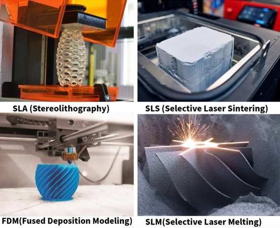
1.SLA for Budget-Friendly, Aesthetically Pleasing Resin Prototypes
SLA (Stereolithography) works by using a UV laser to cure liquid photosensitive resin layer by layer. As a result, this process is primarily used for creating plastic-like aesthetic validation models, such as clear light covers, phone and earphone housings, figurines, promotional models, or small, intricate gears. These are all designed to showcase sharp visual details rather than provide high structural strength or serve functional testing purposes. One crucial point to keep in mind is that photosensitive resin is susceptible to UV degradation and has limited heat and wear resistance. Consequently, visual prototypes produced via SLA should be kept away from direct sunlight and high-temperature environments.
2.SLS for Thermoplastic Functional Prototypes
SLS (Selective Laser Sintering) utilizes a laser to selectively melt (sinter) fine nylon particles, such as PA12 or PA11, within a powder bed to form the shape of the part. Because this sintering approach requires no physical support structures, it allows 3D nesting and highly complex geometric shapes to be realized with ease. Components like snap-fits, living hinges, and internal flow channels are ideal candidates for SLS. However, because sintering is an additive, layer-by-layer process—where the build platform drops by a fraction of a millimeter and a new layer of powder is swept across before the laser fuses it again—it involves a relatively slow cooling phase. This thermal cycle can lead to slight anisotropy in the vertical (Z-axis) direction.
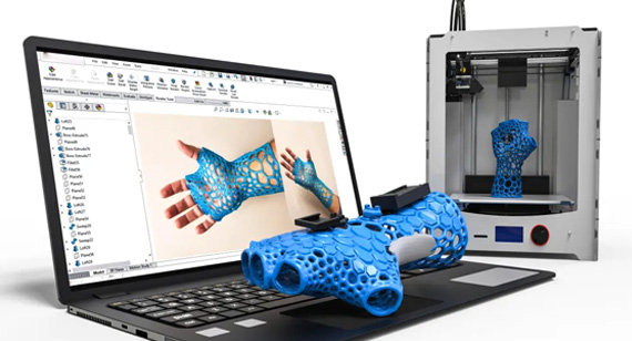
3.FDM for Early Concept Validation of Large-Scale Parts
Fused Deposition Modeling (FDM), also known as Fused Filament Fabrication (FFF), operates by feeding a continuous strand of thermoplastic filament (e.g., ABS, PLA, PETG, PEEK) through a heated nozzle. The heated nozzle extrudes and deposits the molten material along a designated toolpath layer by layer onto the build platform. Since the nozzle moves freely, part size is less constrained, making FDM a budget-friendly option for large structural frames, enclosures requiring high-strength engineering plastics, or low-cost concept models like custom internal assembly fixtures and tooling. The trade-off lies in the surface finish: because the parts are built via extruded beads, visible layer lines remain, resulting in poorer surface smoothness. If cosmetic quality is required, additional post-processing such as sanding or polishing is necessary. Furthermore, due to its layer-by-layer deposition, FDM exhibits lower isotropic strength compared to SLA or SLS.
4.SLM/DMLS for Functional Metal Prototype Parts
Selective Laser Melting (SLM) and Direct Metal Laser Sintering (DMLS) use high-energy laser beams to fully melt or sinter fine metal powders (such as aluminum alloys, stainless steel, and titanium) layer by layer in a controlled atmosphere. This process allows engineers to produce fully dense, high-strength metal prototypes featuring complex internal channels or organic shapes that are nearly impossible to fabricate using traditional CNC machining. While SLM/DMLS delivers mechanical properties close to wrought metals, it comes with higher production costs, requires robust support structures, and typically demands post-processing like stress relief heat treatment and surface finishing.
Selecting the right material is a critical bridge between early concept validation and final production. In rapid prototype 3d printing, material properties directly dictate whether a physical prototype can withstand intended mechanical stress, environmental exposure, or assembly tolerances.
Depending on your engineering requirements, prototype materials generally fall into two primary categories: polymers (plastics) and metals.
1. Polymer and Plastic Materials for Prototyping
Photosensitive Resins (SLA):
Nylon Polymers (SLS):
Engineering Thermoplastics (FDM):
2. Metal Materials for High-Performance Prototypes
When plastic resins cannot meet the thermal or load-bearing demands of functional testing, SLM / DMLS metal 3d printing provides fully dense metal prototypes:
3. Material Selection by 3D Prototype Testing Stage
To optimize both your project timeline and budget, match your material choice to the specific stage of prototype verification:
| Prototyping Stage | Primary Objective | Recommended Materials | Optimal Technology |
| Proof of Concept (PoC) | Visualizing shape, size, and spatial layout | Standard Resin, PLA, ABS | FDM / SLA |
| Form and Fit Testing | Ergonomic checks, clearance and snap-fit assembly | Tough Resin, Nylon PA12 | SLA / SLS |
| Functional and Stress Testing | Load-bearing, thermal resistance, fluid dynamics | Nylon PA12-GF, PEEK, Aluminum Alloy | SLS / FDM / DMLS |
| Pre-Production Validation | Matching end-use physical properties | Stainless Steel, Titanium, Production Thermoplastics | SLM / DMLS / Hybrid CNC |
3d prototype design requires a clear understanding of process-specific limitations. Adhering to Design for Manufacturability (DFM) principles early in the CAD stage prevents print failures, reduces post-processing labor, minimizes material waste, and ensures dimensional accuracy. Below are the core DFM guidelines to follow when preparing CAD models for prototyping in 3d printing:
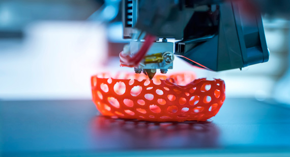
1. Wall Thickness Guidelines
Maintaining proper wall thickness is crucial for structural integrity and preventing thermal warping or collapse during printing.
2. Overhangs, Angles, and Support Structures
Unsupported feature overhangs are one of the most common failure causes of 3D printing in rapid prototyping.
3. Holes, Pins, and Threaded Features
Printing fine details like small holes and threads often presents tolerance challenges due to resin blooming or powder adhesion.
SLA: >= 0.5 mm
SLS / FDM: >= 1.5 mm (smaller holes tend to fuse or close up)
4. Assembly Clearances and Tolerances
To ensure smooth fit and motion when validating multi-part assemblies or snap-fit mechanisms, clear tolerances must be designed directly into the CAD model.
5. Internal Cavities and Powder / Resin Escape Holes
When designing enclosed or hollowed components to reduce weight and material cost, drainage or escape paths are mandatory.
Understanding the key drivers behind manufacturing expenses and production timelines is essential for maintaining a lean development process. In 3D printed prototyping, unit cost and turnaround time are governed by geometric complexity, material volume, and post-processing requirements. By applying smart design strategies early in the engineering phase, you can significantly lower prototype expenses while shortening delivery schedules.
1. Primary Cost Drivers in 3D Printing Prototyping
Bounding Box and Material Volume: Material cost is directly proportional to the physical mass of the part. Larger bounding dimensions and solid interior sections consume more raw resin, powder, or filament, raising overall material expenditure.
Build Height and Machine Time: In layer-by-layer additive manufacturing, Z-axis height dictates the total layer count and overall print duration. Taller parts require more laser passes or extrusion travel, consuming additional machine hours.
Process and Material Grade: Basic SLA resins and FDM filaments offer lower price points. Conversely, high-performance engineering thermoplastics (e.g., PEEK) and SLM metal powders (e.g., Titanium) require sophisticated industrial machinery and higher raw material costs.
Post-Processing Complexity: Manual labor, such as support removal, surface sanding, bead blasting, painting, electroplating, or secondary CNC machining, accounts for a substantial portion of final prototyping costs.
2. Practical Strategies for Cost Reduction
Hollow Out Thick Sections: Convert solid CAD models into hollow shell structures with an appropriate wall thickness (e.g., 2.0 mm to 3.0 mm). Adding internal lattice patterns or escape holes reduces material usage and lowers machine time without compromising structural rigidity.
Optimize Part Orientation: Align parts to minimize Z-axis height on the build platform. Lower vertical profile decreases total print layers, speeding up production and reducing per-part costs.
Minimize Support Structures: Design self-supporting chamfers or $45^\circ$ angles to eliminate unnecessary supports. This cuts raw material consumption and minimizes time-consuming manual cleaning and surface touch-ups.
Standardize Post-Processing: Stick to standard surface finishes (such as raw, bead-blasted, or light sanding) for early-stage functional testing. Reserve high-end polished, painted, or electroplated finishes solely for client-facing or marketing prototypes.
3. How to Optimize Lead Times for Fast Delivery
Prepare Production-Ready CAD Files: Submit fully validated 3D CAD models in standard formats (such as STEP, IGES, or high-resolution STL) along with clean 2D engineering drawings for tight-tolerance features. Clear manufacturing specifications reduce communication back-and-forth.
Leverage Standardized Stock Materials: Select widely stocked materials, such as Standard Resin, Nylon PA12, or ABS, to avoid supply chain delays associated with specialty custom resins or rare metal alloys.
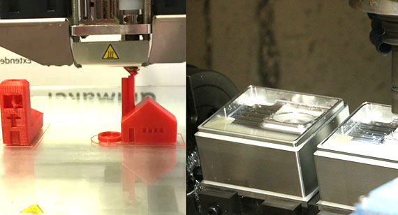
Adopt Hybrid Manufacturing Workflows: Combine 3D printing with secondary CNC machining. Print the overall complex geometric body to save initial tooling time, then perform quick CNC milling or tapping only on critical surfaces and threads to achieve tight tolerances rapidly.
Choosing between additive manufacturing (3d printing in prototyping) and subtractive CNC machining depends on your specific design complexity, material requirements, and budget.
Key Advantages of Rapid 3D Printing vs. CNC Machining
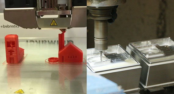
Key Limitations of 3D Printing vs. CNC Machining
Comparison of 3D Printing vs CNC for Prototyping
| Parameter | Rapid 3D Printing | Rapid CNC Machining |
| Geometric Freedom | Exceptional (internal voids and organic shapes) | Limited by cutting tool reach and angle |
| Dimensional Accuracy | Standard (+- 0.05 mm to +- 0.2 mm) | Ultra-precise (+- 0.005 mm to +- 0.01 mm) |
| Structural Integrity | Anisotropic (weaker layer bonds) | Isotropic (maximum solid material strength) |
| Material Waste | Minimal (additive build) | High (subtractive material removal) |
Overall, you can use rapid prototype 3d printing for early-stage design iterations, low-cost concept validation, and complex visual models. Opt for CNC machining when your prototype demands structural load-bearing capacity, extreme precision, or end-use production materials.
Rapid prototype 3d printing has reshaped product development across highly demanding sectors by lowering production risks, accelerating testing, and enabling cost-effective customization. Key industries leveraging this technology include:
Aerospace: You may use 3d printing prototype technology to fabricate lightweight engine components, brackets, and structural frames. High strength-to-weight ratio materials (like titanium and nylon composites) allow for rapid aerodynamic testing and complex geometry validation without expensive tooling.
Healthcare and Medical: 3D printing enables custom-fit prosthetics, patient-specific implants, and tailored surgical instruments. Surgeons also utilize anatomically accurate, 3D-printed organ models derived from patient scan data for pre-operative planning and risk reduction.
Automotive: From interior dashboards and custom ducting to functional engine prototypes, automotive manufacturers can rely on 3d rapid prototyping to perform fit checks and endurance tests, drastically shortening time-to-market for new vehicle iterations.
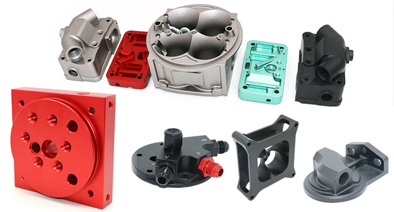
Robotics: Designing robotic grippers, articulated joints, and lightweight drone frames requires rapid design cycles. 3D printing allows engineers to quickly test structural durability and optimize material selection for dynamic, high-load applications.
Jewelry: You can use high-resolution SLA resin printing to create intricate master models for investment casting (lost-wax process). This avoids expensive hand-carving while allowing clients to preview hyper-detailed custom pieces prior to final precious metal casting.
Hybrid Manufacturing for a Custom Engine Housing Prototype
An automotive engineering client approached our factory requiring functional prototype engine housing parts featuring highly intricate internal cooling channels and tight-tolerance mating surfaces (±0.01 mm). Machining the component entirely from a solid metal block using multi-axis CNC milling presented major challenges: standard cutting tools could not reach the complex internal passages, and carving away massive amounts of raw stock would result in excessive material waste, high costs, and an estimated 4-week lead time.
To overcome these constraints, our engineering team implemented a hybrid manufacturing strategy that combined SLM (Selective Laser Melting) Metal 3D Printing with Secondary CNC Machining. We first used 3D printing with AlSi10Mg aluminum alloy to fabricate the main housing body and its complex internal cooling channels to near-net shape. During CAD preparation, we intentionally added a 1.5 mm machining allowance specifically on critical sealing faces, bearing journals, and thread locations.
Following a stress-relief heat treatment in a vacuum furnace, the 3D-printed blanks were transferred to our 5-axis CNC machining center. Our machinists milled the mating faces to achieve a smooth surface finish (Ra 0.8μm), bored the critical bearing journals to exact tolerances, and tapped precision threaded holes. A final CMM inspection and hydrostatic pressure test confirmed that all structural and dimensional specifications were fully met.
By leveraging 3D printing for geometric freedom and secondary CNC machining for high-precision interfaces, we delivered fully functional, test-ready engine prototypes in just 12 business days instead of the initial estimate. This hybrid workflow reduced material waste by 65% and cut total production costs by 32%, providing the customer with an optimal balance of precision, speed, and cost efficiency.
Rapid 3D printing prototyping has fundamentally transformed product development across virtually every industry. Offering rapid lead times, lower initial costs, and exceptional design flexibility, 3d printing in prototyping has become an indispensable tool for applications ranging from aerospace components to consumer goods. However, key factors such as material restrictions, mechanical anisotropy, and build size limits remain important considerations when determining whether additive manufacturing alone fulfills your project's technical demands. As precision CNC machining, prototype 3d printing technology, and other on-demand manufacturing solutions continue to evolve, your team has more options than ever to fabricate fully functional, durable prototypes for rigorous testing, refinement, and optimization prior to full-scale production. Looking for prototype design and cost optimization and the right prototyping manufacturing process for your project? Contact our engineering team today for a free DFM review and a fast, competitive quote. [2D Drawings (PDF files), 3D Drawings (IGS/STP/STEP files)].
Send your 2D drawings, 3D CAD models, prototype material, testing requirements, critical tolerances, surface-finish requirements, quantity and target lead time. VMT will review manufacturability, 3D printing technology, DFM, secondary CNC machining and quotation requirements.
All information and uploaded files are secure and confidential.
1 Tell us what you need
2 Get solution & quote
3 Approve production
Email: inquiry@vimetal.com.cn
What materials cannot be 3D printed?
While the range of printable materials is vast, certain substances remain incompatible with standard 3D printers, including:
Is 3D printing toxic?
Most standard 3D printing materials are safe to handle once cured or cooled, but heating certain filaments (like ABS in FDM printing) can release volatile organic compounds (VOCs) and ultrafine particles. Operating printers in well-ventilated spaces or using air-filtration systems is recommended when working with such materials.
What does CAD stand for in 3D printing?
CAD stands for Computer-Aided Design. It refers to software tools used by engineers to create precise 2D drawings and 3D digital models, which are then exported into printable file formats (such as STEP, STL, or OBJ) for additive manufacturing.
Are there size limits for 3D printed prototypes?
Yes, maximum part size is strictly bound by the build volume of the specific printer. For instance, standard desktop SLA or FDM printers typically max out around 200 x 200 x 200 mm, while industrial SLS or metal printers can handle larger builds up to 600 x 600 x 600 mm. However, larger assemblies can be split into smaller sections in CAD, printed separately, and joined using mechanical fasteners or adhesives.
What is the standard turnaround time for 3D printed prototypes?
Standard turnaround time typically ranges from 1 to 3 business days for simple plastic or resin prototypes, and 3 to 5 business days for complex geometries, metal SLM printing, or parts requiring extensive post-processing (such as painting or electroplating).
Are 3D printed prototypes always cheaper than other prototyping methods?
Not necessarily. While 3D printing is significantly cheaper for single parts, complex visual models, and early design iterations due to zero tooling costs, rapid injection molding often becomes more cost-effective when producing higher quantities (typically 100+ units) or simple geometric blocks.
The technical information and manufacturing advice shared on the VMT website are for general guidance only. While we strive for accuracy, VMT does not guarantee that the processes, tolerances, or material properties mentioned are applicable to every specific project. Any reliance you place on such information is strictly at your own risk. It is the buyer's responsibility to provide definitive engineering specifications for any production orders. Final specifications and service terms shall be subject to the formal contract or quotation confirmed by both parties.


 +86 15099911516




 Read more