15 years one-stop China custom CNC machining parts factory
 431 |
Published by VMT at Nov 17 2024 | Reading Time:About 5 minutes
Are you grappling with parts that don't fit together as intended in your CNC machining projects? Frustrated by costly delays and reworks due to dimensional inaccuracies? You're not alone. Many engineers and manufacturers face challenges in achieving the perfect fit between components, which can compromise the functionality and quality of the final product. But what if understanding the critical concepts of tolerance and allowance could revolutionize your custom CNC machining processes, ensuring seamless assembly and optimal performance?
Tolerance and allowance are fundamental concepts in engineering manufacturing that define the permissible limits of variation in dimensions and the intentional differences between mating parts. Recognizing the difference between tolerance and allowance is essential for precise CNC machined parts, enhancing the efficiency of custom CNC machining, and ensuring the success of your CNC machining services.
Now that we've highlighted how crucial tolerance and allowance are in engineering manufacturing, let's delve deeper into their definitions, importance, and differences. Understanding these concepts will empower you to optimize your CNC machining shop operations, reduce errors, and deliver high-quality CNC prototype machining products that meet exacting standards.
Introduction
In the precision-driven world of engineering manufacturing, the terms tolerance and allowance are often used interchangeably, yet they represent distinct concepts that play pivotal roles in the design and production of components. These concepts are especially critical in custom CNC machining, where achieving exact dimensions is paramount to the functionality and interoperability of CNC machined parts. Misunderstandings or misapplications of tolerance and allowance can lead to parts that do not fit together correctly, resulting in costly reworks, delays, and compromised product integrity.
For professionals in the CNC machining shop environment, mastering the nuances of tolerance and allowance is not just a matter of technical proficiency but also of economic efficiency. Properly applied, these concepts enable manufacturers to produce parts that meet design specifications while optimizing production processes and material usage. This article will explore the definitions, importance, types, and differences between tolerance and allowance, providing a comprehensive understanding crucial for success in CNC prototype machining and CNC machining services.
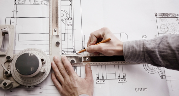
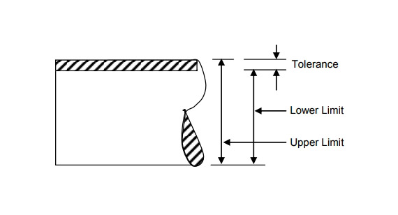
In engineering, tolerance refers to the permissible limit or limits of variation in a physical dimension, a measured value, or physical property of a material or component. Essentially, it defines how much a part's actual dimension is allowed to deviate from the nominal (specified) dimension without adversely affecting the part's functionality or assembly with other components.
For example, if a shaft is designed to be 50 mm in diameter with a tolerance of ±0.05 mm, the acceptable diameter range for the shaft would be from 49.95 mm to 50.05 mm. Any shaft produced within this range is considered acceptable and should function as intended within the assembly.
Tolerance is a critical concept in custom CNC machining because it accounts for the inherent variations that occur during manufacturing processes. Factors such as machine accuracy, tool wear, material properties, and environmental conditions can all influence the final dimensions of a part. By specifying tolerances, engineers communicate acceptable ranges of variation, allowing manufacturers to produce parts that will fit and function correctly despite these variations.
In CNC machined parts, tight tolerances often imply higher precision and quality but may also increase production costs due to the need for more precise machinery, additional processing time, and increased quality control measures. Therefore, balancing the need for precision with production efficiency is a key consideration in CNC machining services.
Tolerances are typically specified on engineering drawings and documentation, using standardized notation and symbols to ensure clear communication between designers and manufacturers. Understanding and correctly applying tolerances is essential for producing parts that meet design requirements and function as intended in their final applications.
Tolerance plays a vital role in manufacturing production, directly impacting the functionality, interchangeability, and quality of CNC machined parts. Here's why tolerance is of paramount importance:
Ensuring Fit and Functionality: Tolerances ensure that parts will fit together properly during assembly. Without appropriate tolerances, components may be too tight or too loose, leading to mechanical failures, inefficiencies, or the inability to assemble parts at all. In applications like aerospace, automotive, or medical devices, precise fits are crucial for safety and performance.
Interchangeability of Parts: Standardized tolerances enable the mass production of parts that are interchangeable, regardless of where or when they are manufactured. This interchangeability simplifies assembly processes, maintenance, and repairs, which is essential in industries relying on custom CNC machining.
Quality Control: Tolerances provide measurable criteria for quality control. By defining acceptable variations, manufacturers can implement inspection processes to ensure parts meet specifications. This reduces the likelihood of defective products reaching customers, maintaining the integrity of CNC machining services.
Cost Efficiency: While tighter tolerances often mean higher production costs due to increased machining time and stricter quality control, specifying unnecessarily tight tolerances can lead to excessive costs without added benefits. Understanding where tight tolerances are essential and where they can be relaxed allows manufacturers to optimize costs without compromising functionality.
Material Utilization: Tolerances influence material usage. Overly tight tolerances may result in higher scrap rates due to parts being rejected for minor deviations. Appropriate tolerance specifications help minimize waste and make efficient use of materials.
Communication and Collaboration: Clear tolerance specifications facilitate better communication between designers, engineers, and manufacturers. This clarity ensures that everyone involved understands the requirements, reducing misunderstandings and errors in the CNC machining shop.
Compliance with Standards: Many industries have stringent regulatory standards that dictate specific tolerances for safety and performance reasons. Adhering to these standards is essential for legal compliance and market acceptance.
In CNC prototype machining, tolerances are equally important as they allow designers to test and validate their designs under real-world conditions. By understanding how tolerances affect part performance, engineers can refine their designs before moving to full-scale production.
Overall, tolerances are a fundamental aspect of engineering manufacturing that directly affects product quality, functionality, and cost. Mastery of tolerance specification and management is essential for any organization involved in CNC machining services.
Engineering tolerances can be categorized in various ways, depending on the aspect of the part or assembly they control. Understanding the different types of tolerances is crucial for accurately specifying and interpreting design requirements in custom CNC machining. The primary types of engineering tolerances include dimensional tolerances, general tolerances, and geometric dimensioning and tolerancing (GD&T). Each type serves a specific purpose and provides different levels of control over the manufactured part's dimensions and geometry.
Dimensional Tolerances
Dimensional tolerances specify the allowable variation in a part's linear dimensions, such as length, width, height, diameter, and thickness. They define the acceptable range of sizes for a particular feature on a part. Dimensional tolerances are typically indicated directly on engineering drawings next to the specified dimension, using symbols such as ± (plus-minus) or by providing upper and lower limit dimensions.
For example, a hole diameter may be specified as 10.00 mm ±0.05 mm, meaning the acceptable diameter ranges from 9.95 mm to 10.05 mm. Alternatively, it might be specified as a range, such as 9.95 mm – 10.05 mm.
Dimensional tolerances are critical in CNC machined parts where precise dimensions are necessary for proper fit and function. They directly affect the ability to assemble components and the performance of the final product. In CNC machining services, achieving the specified dimensional tolerances requires careful control of machining processes, tool selection, and machine calibration.
General Tolerances
General tolerances provide default tolerance values when specific tolerances are not explicitly indicated on the drawing for certain dimensions. They offer a way to avoid cluttering drawings with numerous tolerance specifications while still controlling the quality of the parts.
General tolerances are often defined based on industry standards or company-specific guidelines. For example, ISO 2768 is an international standard that provides general tolerances for linear and angular dimensions without individual tolerance indications.
In practice, a drawing may include a note stating that "All unspecified dimensions are subject to ISO 2768-mK," indicating that medium-level tolerances for dimensions and coarse-level tolerances for form and position apply.
General tolerances are useful in CNC prototype machining and production environments where not all dimensions require tight control. They help streamline the design and manufacturing process by reducing the need for detailed tolerance annotations while ensuring acceptable quality levels.
Geometric Dimensioning and Tolerancing (GD&T)
Geometric Dimensioning and Tolerancing (GD&T) is a symbolic language used on engineering drawings and models to define the allowable variation in the geometry of a part. Unlike dimensional tolerances that control size, GD&T controls the shape, orientation, and position of features.
GD&T provides a comprehensive framework to specify:
By using GD&T, engineers can precisely define how much a feature can deviate from its ideal geometry, ensuring that parts will assemble and function as intended, even when some dimensions vary within specified limits.
In custom CNC machining, GD&T allows for better communication of design intent and can lead to increased manufacturing flexibility and cost savings. It enables the use of tolerances that are more suitable for function rather than defaulting to unnecessarily tight dimensional tolerances.
Implementing GD&T requires a thorough understanding of its principles and symbols. Manufacturers offering CNC machining services must be proficient in interpreting GD&T specifications to produce parts that meet the required standards.
| Symbol |
Characteristics |
Categories |
|
|
Straightness |
Form |
 |
Flatness |
|
 |
Circularity |
|
 |
Cylindricity |
|
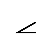 |
Angularity |
Orientation |
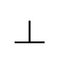 |
Perpendicularity |
|
 |
Parallelism |
|
 |
Position |
Location |
 |
Circular Runout |
Runout |
 |
Total runout |
|
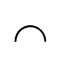 |
Profile of a line |
Profile |
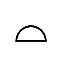 |
Profile of a surface |
Geometric Dimensioning and Tolerancing (GD&T) is an advanced system used to define and communicate engineering tolerances. It employs a set of standardized symbols, rules, and definitions to precisely describe the geometry of mechanical parts and assemblies.
GD&T provides a clear and concise way to specify allowable variations in a part's form, orientation, and location, beyond what can be communicated through traditional linear dimensions and tolerances. It is governed by international standards such as ASME Y14.5 in the United States and ISO standards internationally.
Key Components of GD&T:
Benefits of Using GD&T:
In the context of CNC machining services, GD&T is essential for producing complex CNC machined parts that must meet stringent performance criteria. Manufacturers proficient in GD&T can better interpret customer requirements and ensure that parts are manufactured correctly the first time, reducing rework and delays.
Implementing GD&T requires training and experience. Both designers and manufacturers must be familiar with the standards and capable of applying them effectively. In a CNC machining shop, having personnel skilled in GD&T can be a significant competitive advantage.
Engineering drawings serve as the blueprint for manufacturing parts, conveying critical information about dimensions, tolerances, materials, and finishes. Tolerances are a key aspect of these drawings, and various strategies can be employed to specify them. Understanding these strategies is vital for both designers and manufacturers in custom CNC machining to ensure that parts are produced accurately and efficiently.
Common tolerance strategies include direct limits, positive and negative tolerances, and the use of GD&T symbols. Each approach has its advantages and applications, and the choice of strategy can impact manufacturing processes, costs, and the final product's functionality.
Direct Limits
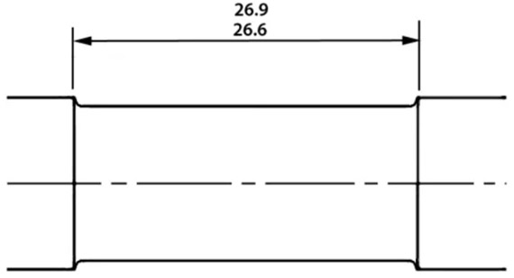
Direct limits involve specifying the maximum and minimum permissible dimensions directly on the drawing. Instead of using a nominal dimension with a plus-minus tolerance, the limits are explicitly stated.
For example, a dimension might be given as:
This approach clearly defines the acceptable size range without requiring additional calculations. Direct limits are particularly useful when the allowable variation is not symmetrical or when specific limits are critical for the part's function.
Advantages of Direct Limits:
Considerations:
In CNC prototype machining, direct limits can be beneficial for testing specific ranges and understanding how variations affect performance.
Positive and Negative Tolerances
Positive and negative tolerances specify the allowable variation above and below the nominal dimension using plus and minus values. This method is widely used and provides a clear understanding of the acceptable dimensional range.
For example:
This indicates that the hole can be up to 10.02 mm but not smaller than 10.00 mm. The asymmetrical tolerance reflects the functional requirements of the part, such as ensuring that a shaft will fit into the hole without being too tight.
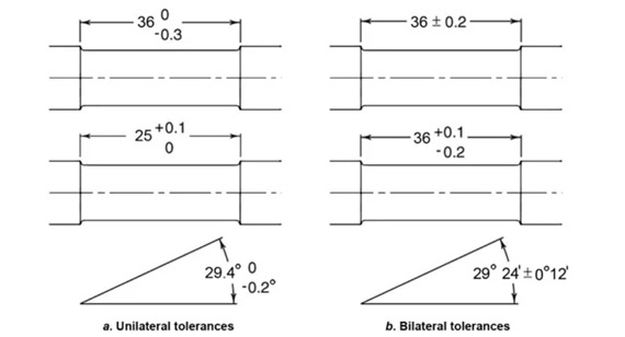
Advantages of Positive and Negative Tolerances:
Considerations:
In CNC machining services, positive and negative tolerances help manufacturers understand the exact requirements and adjust machining processes accordingly.
In engineering, an allowance refers to the intentional difference between the maximum material limits of mating parts to achieve a desired type of fit. It represents the minimum clearance (positive allowance) or maximum interference (negative allowance) between two parts. Allowances are crucial in designing parts that must fit together in a specific way, such as shafts and holes, gears, bearings, and other assemblies.
For example, if a shaft is designed to be slightly smaller than the hole it fits into, the allowance is the difference between the largest permissible shaft diameter and the smallest permissible hole diameter. This ensures that the shaft will always fit into the hole, even when both are at their maximum material condition (MMC).
Key Points About Allowances:
Allowances are determined based on the functional requirements of the assembly, taking into account factors such as material properties, operating conditions, manufacturing processes, and tolerances.
In custom CNC machining, allowances are critical for ensuring that CNC machined parts fit together as intended. Properly calculated allowances contribute to the performance, reliability, and longevity of mechanical systems.
Importance of Allowances:
Understanding and applying allowances requires collaboration between designers and manufacturers. In a CNC machining shop, awareness of allowances helps machinists produce parts that meet the desired fit specifications, enhancing the overall quality of CNC machining services.
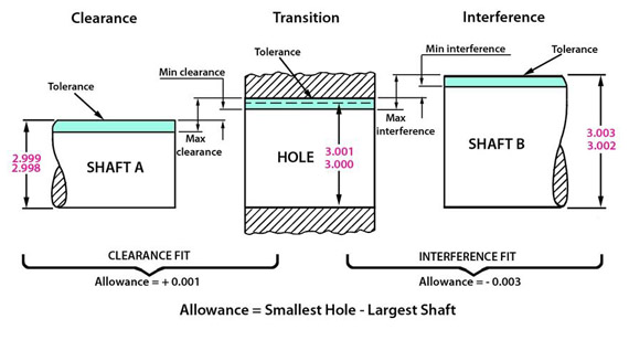
Engineering fits describe the range of tightness or looseness resulting from the combination of allowances and tolerances in mating parts. They define how two components will fit together, which is essential for the assembly and function of mechanical systems.
Types of Engineering Fits are generally classified into three main categories:
Allowances play a key role in determining the type of fit:
Calculating Allowances involves determining the difference between the maximum material conditions (MMC) of the mating parts:
MMC is the condition where the part contains the maximum amount of material within the specified tolerances.
Example:
Hole Diameter:
Shaft Diameter:
Allowance:
Importance of Allowances in Engineering Fits:
In CNC prototype machining, experimenting with different allowances and fits allows designers to test and refine their products before mass production. In CNC machining services, accurately producing parts with specified allowances ensures that assemblies function correctly and meet customer expectations.
Allowances are critical in production for several reasons:
Ensuring Proper Fit: Allowances guarantee that mating parts will assemble as intended, whether requiring a snug fit, easy movement, or a permanent join. This is essential for the functionality of mechanical systems.
Compensating for Variations: Manufacturing processes inherently involve variations. Allowances account for these variations, ensuring that even with slight deviations within tolerances, parts will still fit together correctly.
Facilitating Assembly: Appropriate allowances can simplify assembly processes, reducing the need for adjustments or force-fitting parts. This leads to increased efficiency and reduced labor costs in the CNC machining shop.
Accommodating Material Properties: Materials may change dimensions due to thermal expansion, humidity, or stress. Allowances consider these factors, ensuring that parts maintain proper fit under various operating conditions.
Reducing Wear and Tear: In moving assemblies, allowances help prevent excessive friction or looseness, reducing wear and prolonging the lifespan of components.
Cost Optimization: By carefully calculating allowances, manufacturers can minimize the need for tight tolerances, which can be costly to achieve. This balance helps reduce production costs without compromising quality.
Quality Assurance: Allowances provide clear specifications for acceptable fits, aiding in inspection and quality control processes. This ensures consistent production of high-quality CNC machined parts.
Customer Satisfaction: Delivering products that assemble easily and function reliably enhances customer satisfaction and builds trust in the manufacturer's CNC machining services.
In summary, allowances are a fundamental aspect of engineering design and manufacturing that directly impact the performance, efficiency, and cost-effectiveness of production. They are integral to the successful application of custom CNC machining techniques.
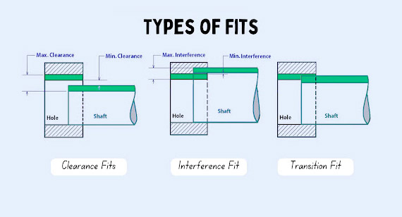
Engineering fits classify the assembly relationships between mating parts based on the combination of their tolerances and allowances. Understanding the different types of fits is essential for designing components that function as intended, whether they need to move freely, fit tightly, or be permanently joined. The three primary types of engineering fits are clearance fits, transition fits, and interference fits. Each type serves specific functional requirements and has implications for manufacturing processes in custom CNC machining.
Clearance Fits
Clearance fits occur when there is always a positive clearance between the mating parts, meaning the shaft is always smaller than the hole. This type of fit allows for easy assembly and disassembly, as well as free movement between parts.
Characteristics of Clearance Fits:
Considerations in CNC Machining:
Transition Fits
Transition fits can result in either a clearance or interference between the mating parts, depending on the actual dimensions achieved within the specified tolerances. They are designed for assemblies where a compromise between tightness and ease of assembly is required.
Characteristics of Transition Fits:
Considerations in CNC Machining:
Interference Fits
Interference fits occur when there is always a negative clearance between the mating parts, meaning the shaft is always larger than the hole. This type of fit results in a tight assembly where the parts are held together by friction after assembly.
Characteristics of Interference Fits:
Considerations in CNC Machining:
Incorporating appropriate tolerances and allowances in part design offers numerous benefits that enhance the functionality, manufacturability, and overall success of a product. These benefits are particularly significant in custom CNC machining, where precision and efficiency are paramount.
1. Ensures Proper Functionality and Fit
By specifying tolerances and allowances, designers ensure that parts will fit together as intended, enabling the mechanical system to function correctly. This is essential for moving assemblies, load-bearing structures, and components requiring precise alignment.
2. Optimizes Manufacturing Processes
Understanding the necessary tolerances allows manufacturers to select appropriate machining processes, tools, and equipment. This optimization leads to increased efficiency, reduced production time, and lower costs in the CNC machining shop.
3. Reduces Material Waste and Costs
Proper tolerancing minimizes the production of non-conforming parts, reducing scrap rates and material waste. It also prevents over-engineering, where unnecessarily tight tolerances lead to increased machining costs without added value.
4. Enhances Quality Control
Clear tolerance specifications facilitate inspection and quality control processes. Manufacturers can easily verify whether parts meet the required standards, ensuring consistent quality in CNC machining services.
5. Improves Assembly Efficiency
Parts designed with appropriate allowances assemble more easily, reducing labor costs and assembly time. This efficiency is crucial in mass production and complex assemblies.
6. Accommodates Material and Environmental Factors
Tolerances and allowances account for material properties, thermal expansion, and environmental conditions. This consideration ensures that parts maintain functionality under various operating conditions.
7. Increases Product Reliability and Longevity
By preventing issues such as excessive wear, misalignment, and mechanical failure, proper tolerancing and allowances contribute to the reliability and longevity of the product.
8. Facilitates Interchangeability
Standardized tolerances allow for the interchangeability of parts, simplifying maintenance, repairs, and upgrades. This interchangeability is vital in industries where downtime is costly.
9. Enhances Customer Satisfaction
Delivering products that perform as expected and assemble without issues enhances customer satisfaction. It builds trust in the manufacturer's capabilities and can lead to repeat business and referrals.
10. Supports Compliance with Standards
Many industries have specific standards and regulations regarding tolerances and fits. Adhering to these standards is essential for legal compliance and market acceptance.
In CNC prototype machining, incorporating tolerances and allowances during the design phase allows for realistic testing and validation. It helps identify potential issues early, saving time and resources before full-scale production.
Overall, the thoughtful incorporation of tolerances and allowances is a fundamental aspect of engineering design that directly impacts the success of manufacturing processes and the quality of the final product.
While allowances and tolerances are both critical concepts in engineering manufacturing, they serve different purposes and are applied in distinct ways. Understanding the differences between allowances and tolerances is essential for accurate part design, manufacturing, and assembly in custom CNC machining. This section explores their definitions, purposes, types, and applications, highlighting how they interact and influence each other.
Definition
Purpose
Types
Tolerance:
Allowance:
Material and Lubrication Effects
Adjustability
Functions in Compilation
Typical Applications
| Aspect |
Tolerance |
Allowance |
|
Definition |
Tolerance means the permissible deviation from a defined dimension or feature of a mechanical part. |
It is the intentional gap between components of an assembly. |
| Purpose |
Tolerance ranges help control quality by defining the acceptable variation range while accommodating manufacturing variability. |
Allowance ensures mating parts fit correctly, considering variables such as thermal expansion, manufacturing variations, lubrication, etc. |
| Types |
Upper limit (positive value) and lower limit (negative value). |
Clearance (positive value) or interference (negative value). |
| Material and Lubrication Impact |
Material and lubrication may influence the need for looser or tighter tolerances. |
Material and lubrication may affect the ideal allowance values. |
|
Adjustability |
Engineering tolerances do not permit variability in part dimensions but allow for manufacturing variations. |
Allowance in engineering permits varying levels of gap or overlap between mechanical parts to create the desired fit. |
| Function in Assembly |
Defines the acceptable range of dimensions for features, parts, and assemblies. |
It dictates the type of fit between mating parts. |
| Typical Application |
Product engineers use tolerances to control the acceptable range of a mechanical part’s lengths, diameter, or other dimensions. |
It is suitable for indicating how freely mating parts should move (clearance) or how they should be press-fitted (interference). |
In the intricate world of engineering manufacturing, mastering the concepts of tolerance and allowance is essential for producing high-quality, functional, and cost-effective products. These concepts are fundamental in custom CNC machining, where precision and efficiency are paramount.
Tolerance manages the inherent variations in manufacturing processes, ensuring that individual parts meet dimensional requirements and function correctly. It balances the need for precision with practical considerations of cost and manufacturability.
Allowance focuses on the intentional differences between mating parts, controlling how they fit together in assemblies. It ensures that components will assemble with the desired level of tightness or looseness, directly impacting the performance and reliability of mechanical systems.
Understanding the differences between tolerance and allowance allows engineers and manufacturers to design and produce CNC machined parts that meet exacting standards. It enhances communication between designers and machinists, streamlines production processes, and contributes to the overall success of CNC machining services.
By carefully considering and applying tolerances and allowances, organizations can optimize manufacturing efficiency, reduce costs, improve product quality, and increase customer satisfaction. In a competitive market, this mastery sets companies apart, positioning them as leaders in precision engineering and manufacturing.
At VMT CNC Machining Services Factory, we specialize in providing high-precision custom CNC machining solutions tailored to your specific needs. Our state-of-the-art CNC machining shop is equipped with advanced machinery and operated by a team of experienced professionals who understand the critical importance of tolerances and allowances in engineering manufacturing.
Our Services Include:
Why Choose VMT:
Partner with VMT CNC Machining Services Factory to experience the difference that precision, expertise, and dedication can make in your projects. Contact us today to discuss your requirements and discover how we can help you achieve your engineering goals.
What Is the Difference Between Tolerance and Clearance?
Tolerance refers to the permissible variation in a part's dimensions, specifying how much a dimension can deviate from the nominal value. It accounts for manufacturing imperfections.
Clearance is a type of allowance where there is always a positive difference between the sizes of mating parts, resulting in a gap that allows for easy assembly and movement.
In essence, tolerance controls dimensional variations in individual parts, while clearance describes the intentional space between assembled parts.
What Are the 4 Types of Form Tolerances?
The four types of form tolerances in Geometric Dimensioning and Tolerancing (GD&T) are:
These form tolerances ensure that individual features meet specific geometric requirements, independent of orientation or position.
What Is the Difference Between Tolerance and Limit?
Tolerance specifies the permissible variation in a dimension, defining how much a part can deviate from the nominal size.
Limit refers to the maximum and minimum sizes allowed for a dimension, effectively the upper and lower bounds within which the part must be manufactured.
Tolerance is the difference between these limits. For example, if a dimension has limits of 10.05 mm and 9.95 mm, the tolerance is ±0.05 mm.
What Is the Difference Between Tolerance and Clearance?
This question repeats the first one.
Tolerance manages the acceptable variations in the size of individual parts during manufacturing.
Clearance refers to the intentional space between mating parts in an assembly, ensuring that they fit together with room for movement.
What Are the Most Common Tolerances?
Common tolerances vary by industry and application but often include:
The most appropriate tolerance depends on the functional requirements of the part and the capabilities of the manufacturing process.
What Is the Allowance in GD&T?
In GD&T, allowance is not explicitly defined as a separate concept but relates to the intentional difference between mating parts to achieve a desired fit. It can be associated with the concept of Maximum Material Condition (MMC) and Least Material Condition (LMC), which are used to define the worst-case scenarios for material limits in features.
Allowance ensures that even at MMC, parts will fit together as intended, whether requiring clearance or interference.
By understanding and applying the concepts of tolerance and allowance effectively, engineers and manufacturers can enhance the precision, functionality, and efficiency of their products. This knowledge is essential for success in the competitive field of CNC machining services.
